Export PDF

RGBlink
FLEX 16pro

User Manual

FLEX 16pro

720-0016-01-0

RGBlink

www.rgblink.com

November 2026

1FLEX 16pro-Specification

FLEX 16pro: Multi-screen Splicing Processor (All-In-One)
Key Features + Modular I/O configuration — optional 4×4, 2×6, or 6×2 input/output combo modules + Up to 4 I/O combo modules per chassis + 4K60 support — 3840×2160@60Hz input and output + Advanced display functions — video wall splicing, roaming, cross-screen, scaling, PIP, POP, and overlay for any video signal + Multi-window capability — up to 4 windows per screen; full wall layer stacking up to 4×N layers (N = number of screens) + Signal preview and wall monitoring — real-time input preview and output feedback + Web-based control — switch preset scenes from PC, phone, or tablet via web browser + 1000+ preset scenes storage capacity + Scene auto-rotation — customizable rotation intervals + Seamless scene switching — < 30ms delay, no stutter, no blue screen, no flicker + Ultra HD subtitles and background image support + LSupports source and display device validity detection with status LED indication. + Frame-synchronized outputs — 0ns port-to-port timing difference (excluding display panel variance) + Multi-user management + Compatible with third-party central control systems including Crestron, AMX, QSC, Companion, etc.
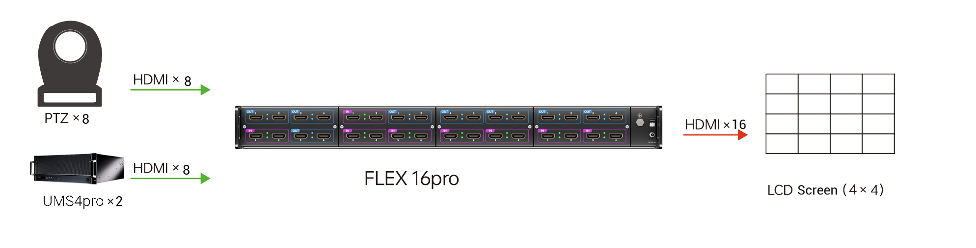
Application
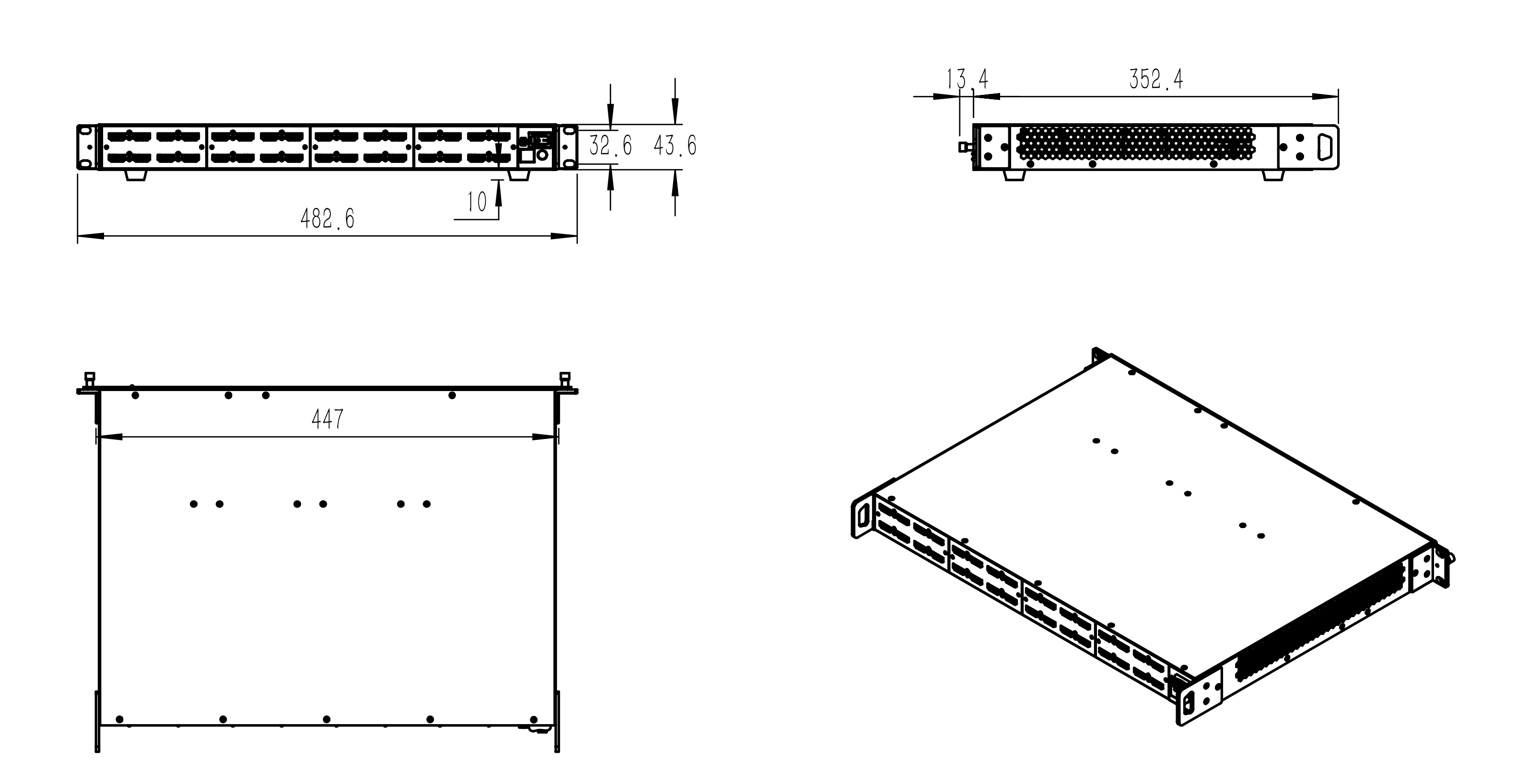
Dimension (mm)

Connectors

I/O Module(Optional)4 × 42 × 66 × 2
InputINHDMI4 × HDMI-A2 × HDMI-A6 × HDMI-A
OutputOUTHDMI4 × HDMI-A6 × HDMI-A2 × HDMI-A
ItemDescription
OutputOUTAudio1 × 3.5mm phone jack
ControlIR1 × 3.5mm phone jack
LAN1 × RJ45
RS2321 × RJ45
PowerPower1 × DC Jack

Performance

ItemDescription
ResolutionInputUp to RGB 8bit 3840×2160@60, YCbCr422 8bit 10bit 12bit 3840×2160@60
OutputUp to 3840x2160@60

Power

ItemDescription
PowerDC 12V/12A

Working Environment

ItemDescription
Operating Temperature0°C - 40°C
Relative Humidity10 - 90% RH (non-condensing)

Physical

ItemDescription
Net Weight4.25KG (Full load: with four modules)
Net Dimension437mm × 236mm × 44mm

Order Codes

Product CodeItem
720-0016-01-0FLEX 16pro
792-0404-01-04 × 4 I/O Module
792-0206-01-02 × 6 I/O Module
792-0602-01-06 × 2 I/O Module

2FLEX 16pro-Quick Start

Welcome to the Quick Start Guide.

Follow the steps in this guide to quickly set up your device and get started.

2.1Product Overview

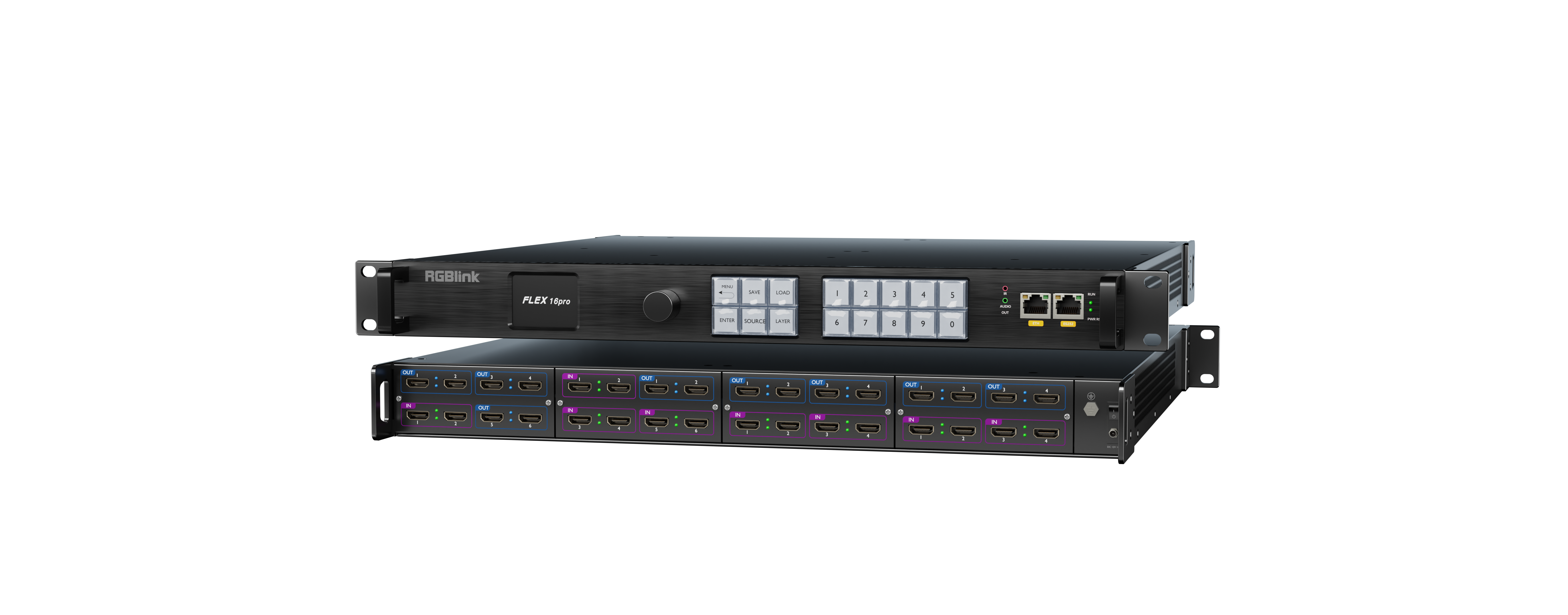
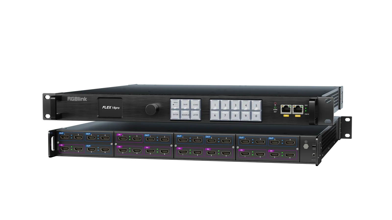
FLEX 16pro is a 1U rack‑mountable, fully modular 4K video wall processor featuring a new hardware architecture with the smallest footprint among traditional 16‑screen solutions.

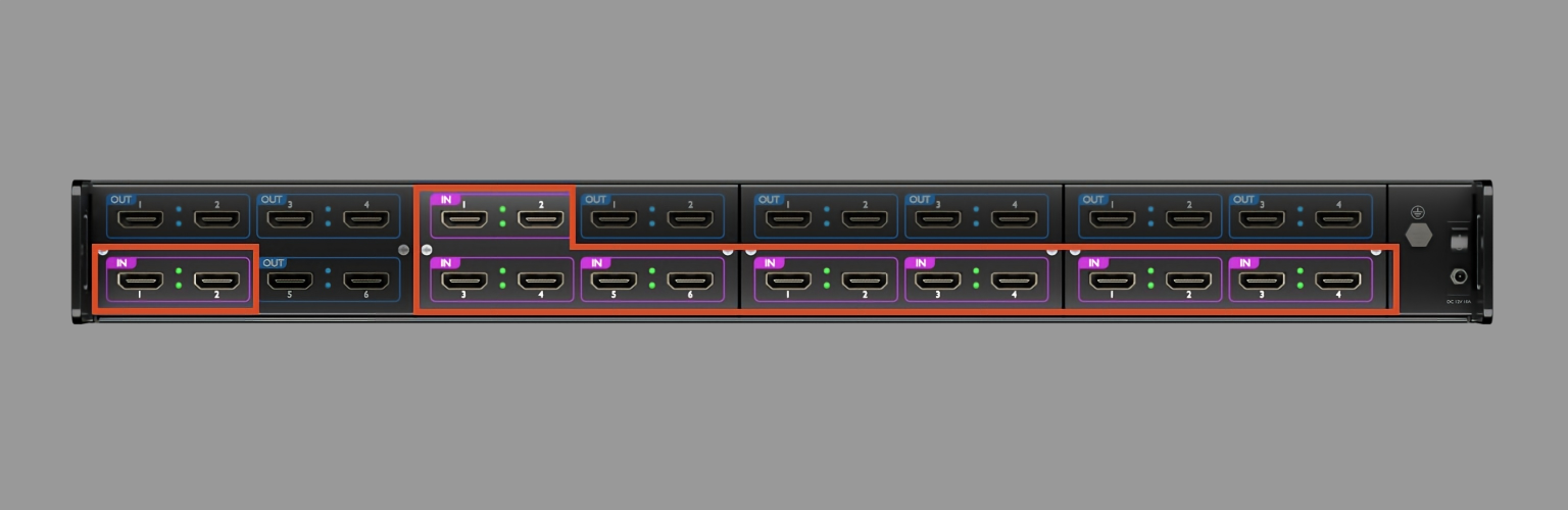
Each unit supports up to 4 optional modules and each module has three options: 2‑in/6‑out, 4‑in/4‑out, or 6‑in/2‑out. These can be flexibly combined to cover a wide range of scenarios from 8-in/24-out to 24‑in/8‑out.

Up to 4 windows per screen, CUT switching, web-based management and openAPI.

Key Features

  • Modular I/O configuration — optional 4×4, 2×6, or 6×2 input/output combo modules.
  • Up to 4 I/O combo modules per chassis.
  • 4K60 support — 3840×2160@60Hz input and output.
  • Advanced display functions — video wall splicing, roaming, cross-screen, scaling, PIP, POP, and overlay for any video signal.
  • Multi-window capability — up to 4 windows per screen; full wall layer stacking up to 4×N layers (N = number of screens).
  • Signal preview and wall monitoring — real-time input preview and output feedback.
  • Web-based control — switch preset scenes from PC, phone, or tablet via web browser.
  • 1000+ preset scenes storage capacity.
  • Scene auto-rotation — customizable rotation intervals.
  • Seamless scene switching — < 30ms delay, no stutter, no blue screen, no flicker.
  • Ultra HD subtitles and background image support.
  • LSupports source and display device validity detection with status LED indication.
  • Frame-synchronized outputs — 0ns port-to-port timing difference (excluding display panel variance).
  • Multi-user management.
  • Compatible with third-party central control systems including Crestron, AMX, QSC, Companion, etc.

2.1.1In the Box

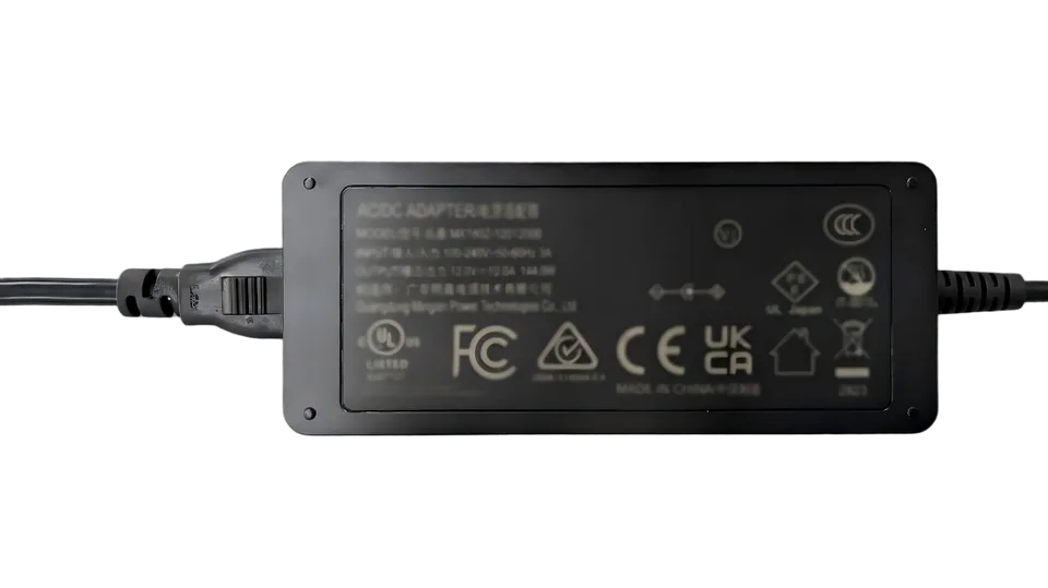
  • DC12V/12A Power Adapter×1
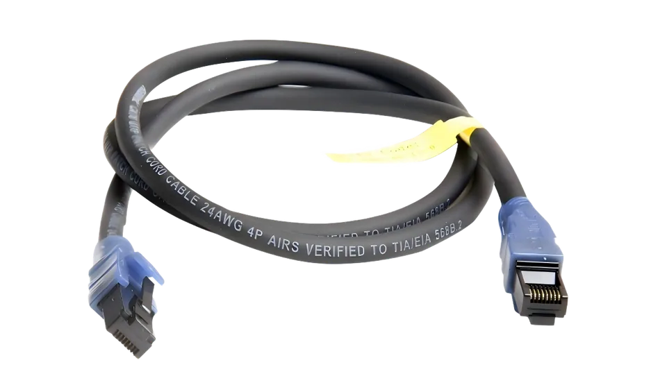
  • CAT 6 Cable×1

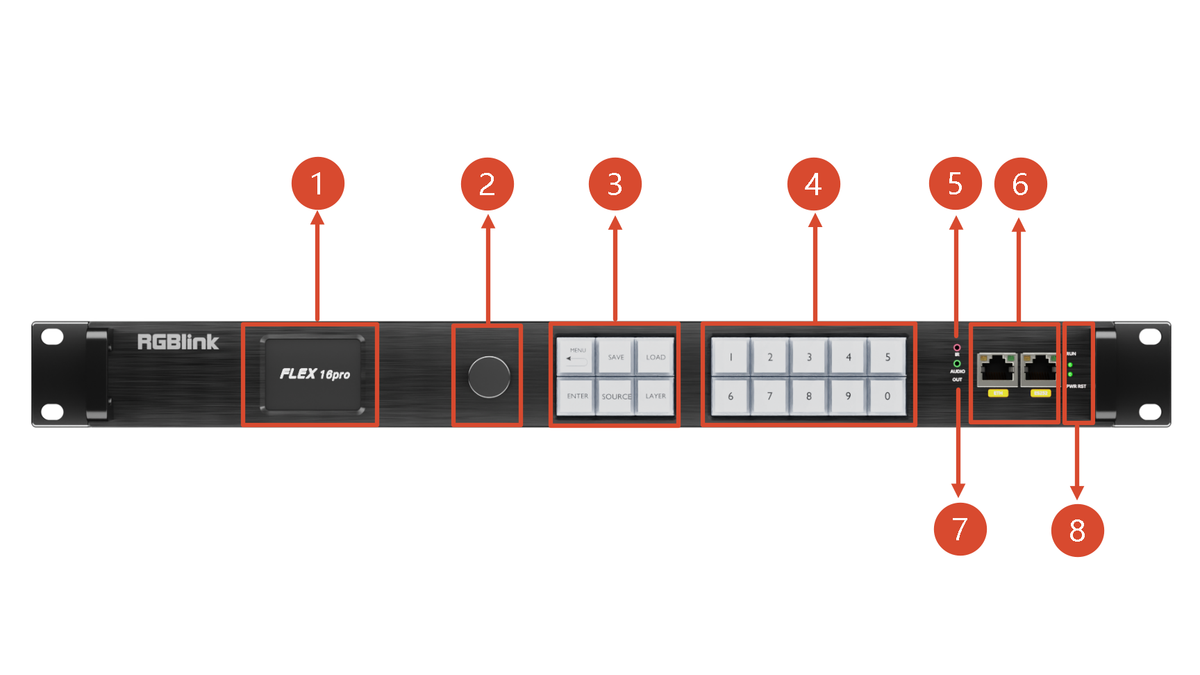
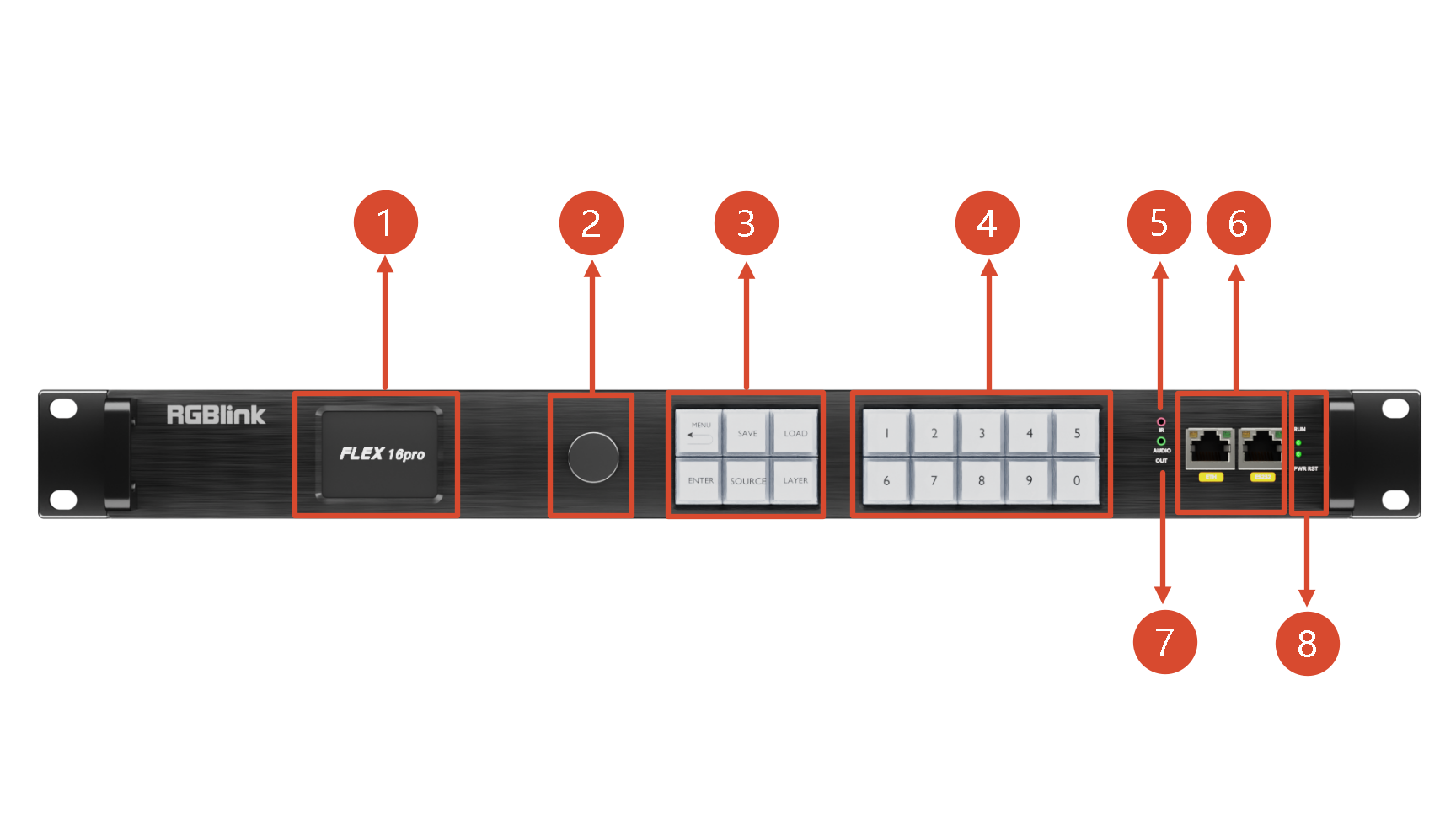
2.1.2Front Panel

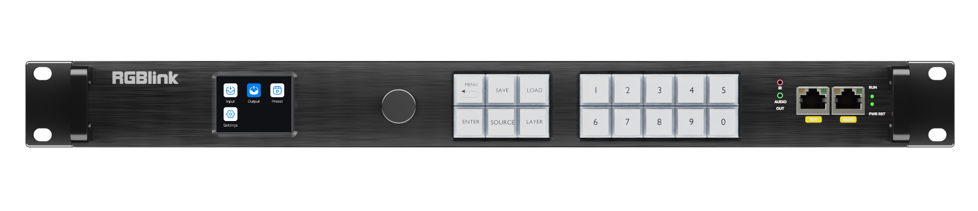
No.NameDescription
1LCD ScreenDisplays device menu and status
2KnobSelects menu functions and confirms
3Function ButtonsMENU: Open the menu/Return to the previous menu level ENTER: Confirm SAVE: Open the Preset Save menu LOAD: Open the Preset Load menu SOURCE: / LAYER: /
4Numeric ButtonsUsed for numbers input
5IRInfrared receiver interface
6Communication InterfacesLAN: 10M/100M adaptive network port for network communication RS232: Serial communication
7Audio OutputIndependent audio output port, de-embeds audio from one of the input channels
8IndicatorsRUN: Working indicator, green solid = operating normally PWR RST: Power/Reset indicator, red solid = powered on; red flashing = device resetting

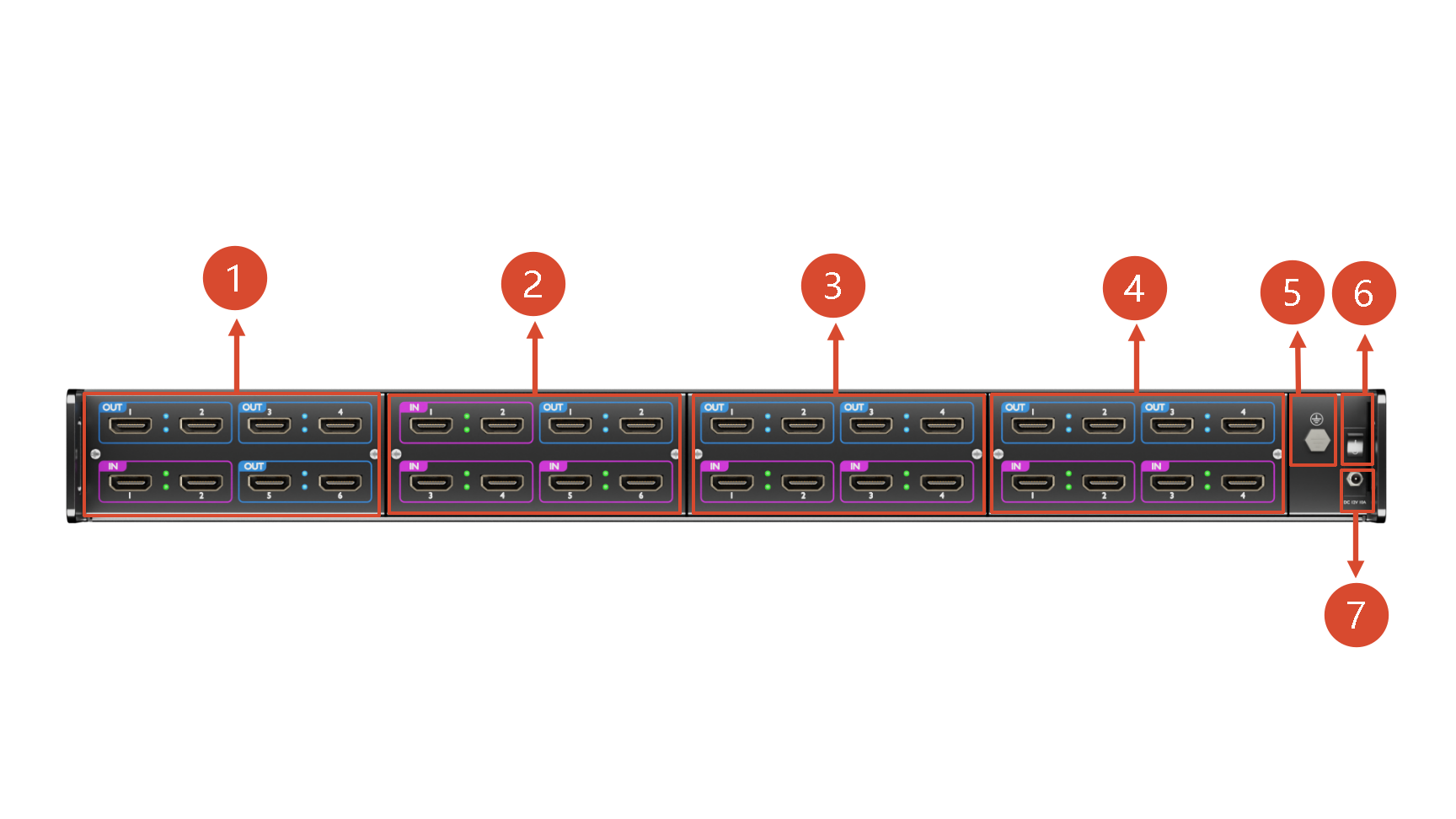
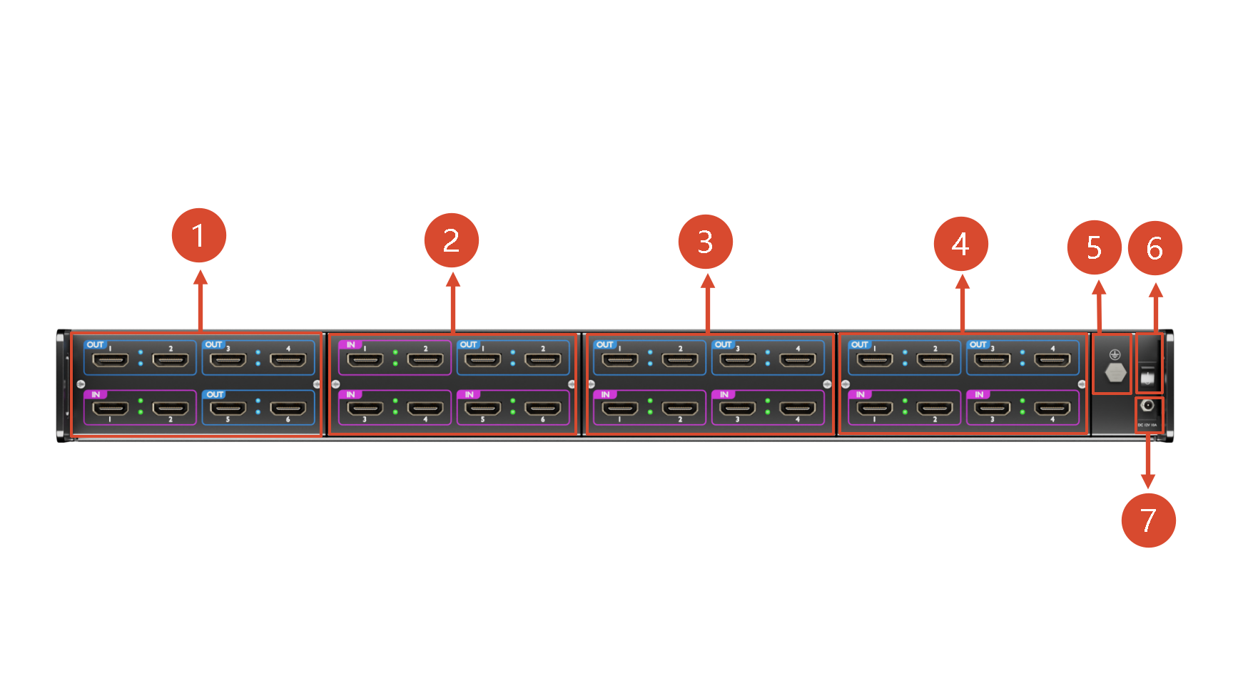
2.1.3Ports Info

No.NameDescription
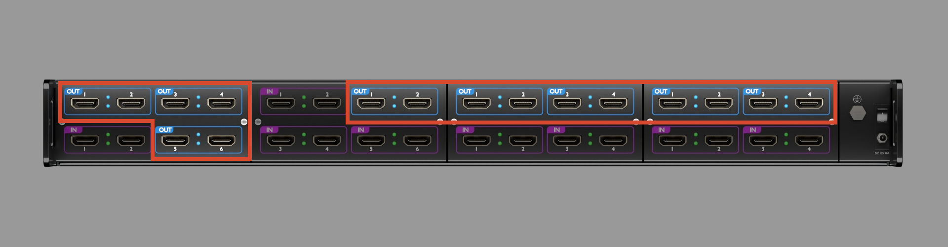
1Optional I/O Combo2×6 I/O; 2×HDMI Input & 6×HDMI Output
26×2 I/O; 6×HDMI Input & 2×HDMI Output
34×4 I/O; 4×HDMI Input & 4×HDMI Output
44×4 I/O; 4×HDMI Input & 4×HDMI Output
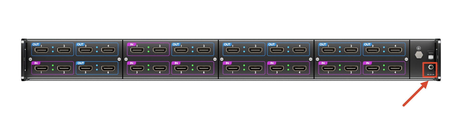
5Grounding Screw
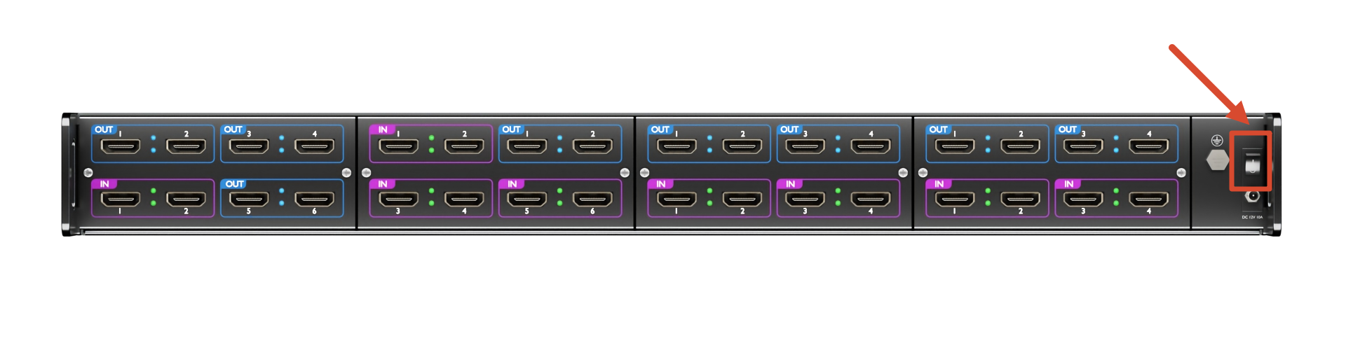
6Power SwitchFirmware upgrade interface
7DC 12V 12AThreaded anti-detach DC connector

2.2Use Your Product

Refer to this chapter for operating instructions.

2.2.1Web Control

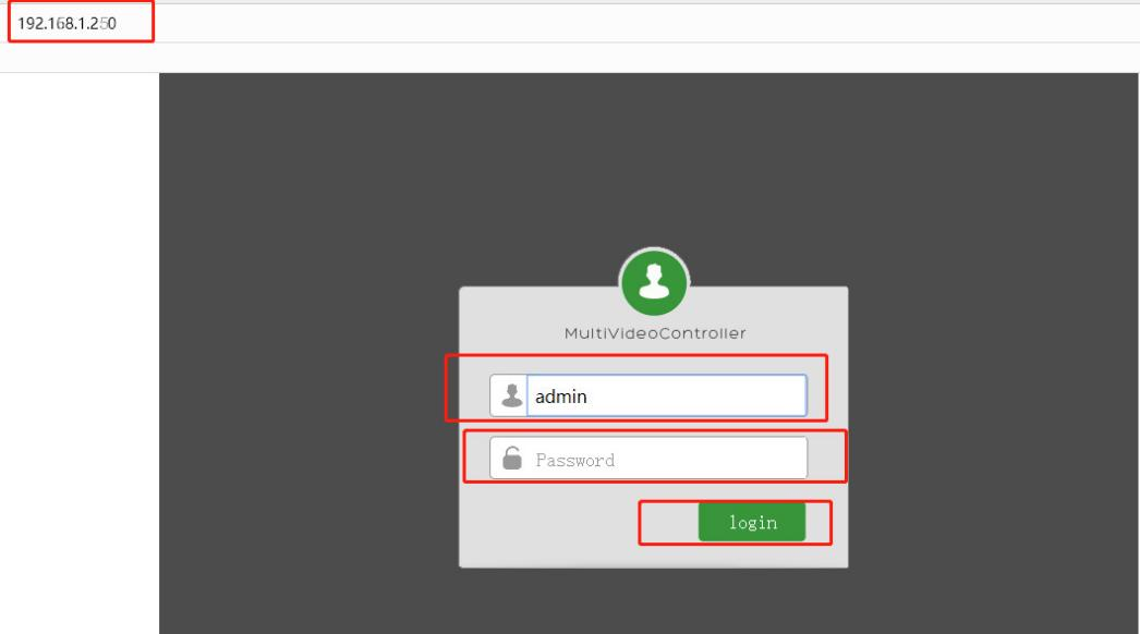
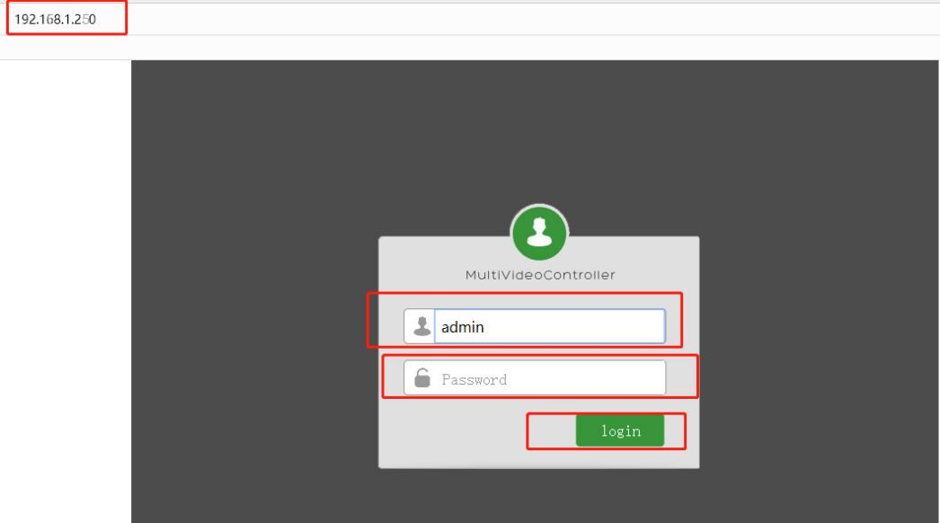
Web Login

Open a browser and enter the processor's IP address in the address bar (factory default IP: 192.168.1.250). The Web login page will appear. Enter the account and password to log in. Default account: admin, password: (empty by default); as shown below:

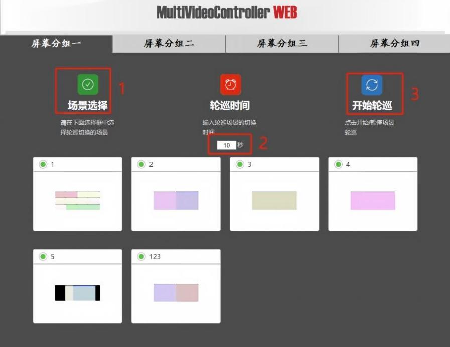
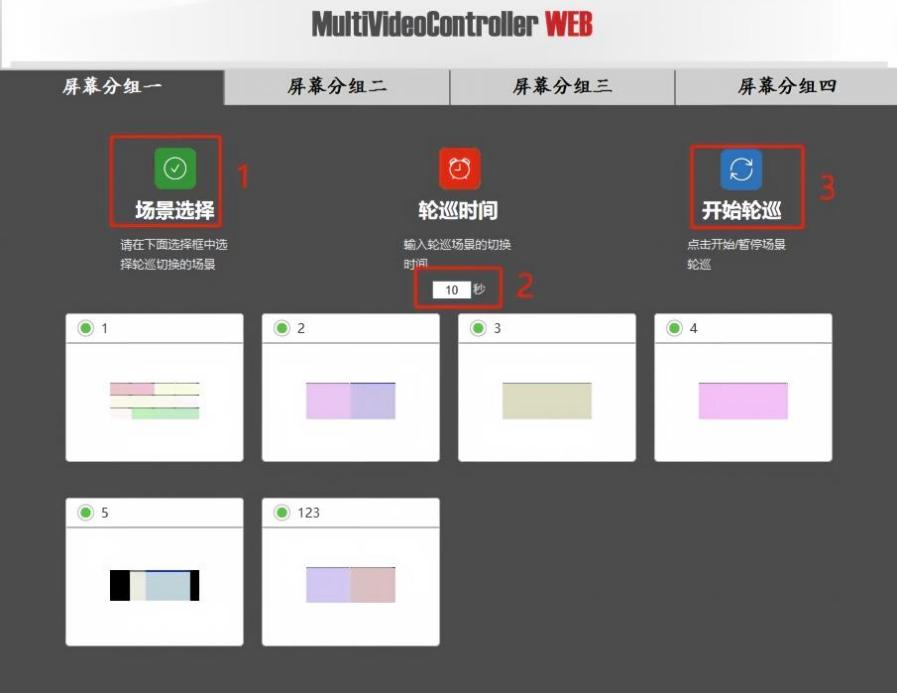
Web Operation

After successful login, click the desired scene to recall it. You can also set automatic scene rotation. As shown below:

2.2.2API Control

This system supports HTTP and serial control methods.

HTTP Control Method

HTTP Port: 80.

Keep-alive mode is not supported.

Unless otherwise specified, the POST or GET URL for the interfaces below is: http://host_ip_address/index2.html

Login

Request typePOST
ContentJson: { "Command" : "Login", "UserName" : "Username", "Password" : "MD5 string of password" }
ResponseJson: { "Status" : "Ok"/"Error", "SessionId" : Session ID of this login -- valid when status is ok, "ScreenGroup" : [Screen group permissions, 1 = can operate, 0 = cannot operate], "Message" : "Error message" }
📢  Notes 

The session ID must be saved for subsequent use.

Get Host Scene List

This command retrieves the scene list corresponding to the screen group specified by ScreenGroup.

Request typeGET
Header containssession_id=session id
ContentCommand=GetAllModal&ScreenGroup=Screen group number (1~4)
ResponseJson: { "Status":"Ok"/"Error", "ModalList":["Scene Name", "Scene Name", ...] }

Get Host Scene Thumbnail

Request typeGET
URLhttp://xxx.xxx.xxx.xxx/scene_name.jpg
Header containssession_id=session id
ResponseImage data

Switch Scene

Request typePOST
Header containssession_id=session id
ContentJson: { "Command" : "LoadModal", "ScreenGroup" : Screen group number (1~4), "ModalName" : "Scene Name" }
ResponseJson: { "Status" : "Ok"/"Error", "Message" : "Error message" }

Serial Control Method

Serial Configuration

  • Baud Rate: 9600
  • Parity: None
  • Flow Control: None
  • Data Bits: 8
  • Stop Bits: 1

If using RJ45 network cable to connect to the processor serial port, pin 1 is our TX, pin 2 is our RX, pin 6 is our GND; other pins are disconnected. RJ45 pinout diagram is as follows:

(Refer to original document for RJ45 pinout diagram)

If using DB9 serial cable to connect to the processor serial port, pin 3 is our TX, pin 2 is our RX, pin 5 is our GND. DB9 pin definitions are as follows:

(Refer to original document for DB9 pin definition diagram)

Packet Format

Commands sent from the control system to the device, and responses from the device to the control system, are both encapsulated into data packets. Each packet starts with the $ character and ends with the ^ character, as shown below:

Op indicates the operation command, one character.
Scr indicates the screen group number to be operated, one character.

Format: $ Op Scr DATA ^

The processor control system supports both string commands and hexadecimal commands. The control device can send either string commands or hexadecimal commands to the processor, both of which can be processed. Hexadecimal commands are the ASCII codes of the string.

Serial Commands

Get Host Scene List

Op1
ScrOne byte, value 1 to 4, specifying the screen group number
DATANone
ExamplesGet screen group 1 scenes: $11^ Get screen group 2 scenes: $12^ Get screen group 3 scenes: $13^ Get screen group 4 scenes: $14^
Device ResponseOp: 1 DATA: Multiple scene names separated by spaces (UTF8 format). Example: Scene1 Scene2

Get Current Window List

Op2
ScrOne byte, value 1 to 4, specifying the screen group number.
DATANone
ExamplesGet screen group 1 window list: $21^ Get screen group 2 window list: $22^ Get screen group 3 window list: $23^ Get screen group 4 window list: $24^
Device ResponseOp: 2 DATA: Multiple window information separated by brackets, window info format is [WindowID,Top-left X,Top-left Y,Bottom-right X,Bottom-right Y]. Example: 2[21326,0,0,960,540][25588,960,0,1920,540]...[13336,5760,8100,6720,8640][9651,6720,8100,7680,8640]

Switch Scene

Op3
ScrOne byte, value 1 to 4, specifying the screen group number
DATAScene name (UTF8 format)
ExamplesSwitch screen group 1 to "Scene5": $31Scene5^ Switch screen group 2 to "ab": $32ab^ Switch screen group 3 to "123ab": $33123ab^ Switch screen group 4 to "Scene6a": $34Scene6a^ Scene name "1" code: 24 33 31 31 5E Scene name "2" code: 24 33 31 32 5E Scene name "3" code: 24 33 31 33 5E
Device ResponseOp: 3 DATA: Ok or Error

Open Window with Signal Source

Op4
ScrOne byte, value 1 to 4, specifying the screen group number
DATA[WindowID][Input Slot 1-16][Input Port 1-8][Top-left X,Top-left Y,Bottom-right X,Bottom-right Y] Window ID must be an integer >=1, with uniqueness; multiple windows cannot have duplicate IDs.
ExamplesOpen input slot 2 port 3 on group 1, window ID=2, coords 1920,1080,3840,2160: $41[2][2][3][1920,1080,3840,2160]^ Hex code: 24 34 31 5B 32 5D 5B 32 5D 5B 33 5D 5B 31 39 32 30 2C 31 30 38 30 2C 33 38 34 30 2C 32 31 36 30 5D 5E
Device ResponseOp: 4 DATA: Ok or Error

Switch Window Signal Source

Op5
ScrOne byte, value 1 to 4, specifying the screen group number
DATA[WindowID][Input Slot 1-16][Input Port 1-8] Window ID can be obtained via Get Current Window List interface.
ExamplesSwitch input slot 2 port 3 to window ID 21326 on group 1: $51[21326][2][3]^ Hex code: 24 35 31 5B 32 31 33 32 36 5D 5B 32 5D 5B 33 5D 5E
Device ResponseOp: 5 DATA: Ok or Error

Get Processor IP

Op6
ScrNone
DATANone
Example$6^
Device ResponseOp: 6 DATA: Processor IP. Example: IP:[192.168.1.250]

Set Processor IP Address

Op7
ScrNone
DATAIP address
ExampleSet processor IP address to 192.168.1.200: $7192.168.1.200^
Device ResponseOp: 7 DATA: Ok or Error

Reset Processor

Op8
ScrNone
DATANone
Example$8^
Device ResponseOp: 8 DATA: Ok or Error, device restarts after successful reset

Switch Audio Channel

Op9
ScrNone
DATA[Input Slot 1-16][Input Port 1-8] To close audio input, set both input slot and input port to 0.
ExamplesSwitch to slot 2 port 3: $9[2][3]^ Close audio input: $9[0][0]^ Switch to slot 2 port 3 hex code: 24 39 5B 32 5D 5B 33 5D 5E Close audio hex code: 24 39 5B 30 5D 5B 30 5D 5E
Device ResponseOp: 9 DATA: Ok or Error

Close Window

Op0
ScrOne byte, value 1 to 4, specifying the screen group number
DATA[WindowID] To close all windows in current group, set WindowID to 0.
ExamplesClose group 2 window ID 1: $02[1]^ Close group 1 all windows: $01[0]^ Close group 2 window ID 1 hex: 24 30 32 5B 31 5D 5E Close group 1 all windows hex: 24 30 31 5B 30 5D 5E
Device ResponseOp: 0 DATA: Ok or Error

Move Window

Opa
ScrOne byte, value 1 to 4, specifying the screen group number
DATA[WindowID][Top-left X,Top-left Y,Bottom-right X,Bottom-right Y] Window ID can be obtained via Get Current Window List interface. 0509 point-to-point mode does not support window operations.
ExampleMove group 1 window ID 1 to 1920,1080,3840,2160: $a1[1][1920,1080,3840,2160]^ Hex code: 24 61 31 5B 31 5D 5B 31 39 32 30 2C 31 30 38 30 2C 33 38 34 30 2C 32 31 36 30 5D 5E
Device ResponseOp: a DATA: Ok or Error

2.3Revision History

VersionDateDescriptionAuthor
V1.02026-08-24First release.ZFH

3FLEX 16pro-User Manual

Thank you for choosing RGBlink FLEX 16pro.

This manual provides information on the device features, installation and operation.

Before using the device for the first time, please read this manual carefully to ensure safe and proper use of the product.

3.1About Your Product

Meet FLEX 16pro

FLEX 16pro is a 1U rack‑mountable, fully modular 4K video wall processor featuring a new hardware architecture with the smallest footprint among traditional 16‑screen solutions.

Each unit supports up to 4 optional modules and each module has three options: 2‑in/6‑out, 4‑in/4‑out, or 6‑in/2‑out. These can be flexibly combined to cover a wide range of scenarios from 8-in/24-out to 24‑in/8‑out.

Up to 4 windows per screen, CUT switching, web-based management and openAPI.

Key Features

  • Modular I/O configuration — optional 4×4, 2×6, or 6×2 input/output combo modules.
  • Up to 4 I/O combo modules per chassis.
  • 4K60 support — 3840×2160@60Hz input and output.
  • Advanced display functions — video wall splicing, roaming, cross-screen, scaling, PIP, POP, and overlay for any video signal.
  • Multi-window capability — up to 4 windows per screen; full wall layer stacking up to 4×N layers (N = number of screens).
  • Signal preview and wall monitoring — real-time input preview and output feedback.
  • Web-based control — switch preset scenes from PC, phone, or tablet via web browser.
  • 1000+ preset scenes storage capacity.
  • Scene auto-rotation — customizable rotation intervals.
  • Seamless scene switching — < 30ms delay, no stutter, no blue screen, no flicker.
  • Ultra HD subtitles and background image support.
  • LSupports source and display device validity detection with status LED indication.
  • Frame-synchronized outputs — 0ns port-to-port timing difference (excluding display panel variance).
  • Multi-user management.
  • Compatible with third-party central control systems including Crestron, AMX, QSC, Companion, etc.

3.1.1In the Box

1×DC 12V/12A Power Adapter1×CAT 6 Cable
Document imageDocument image

3.1.2Front Panel

No.NameDescription
1LCD ScreenDisplays device menu and status
2KnobSelects menu functions and confirms
3Function ButtonsMENU: Open the menu/Return to the previous menu level ENTER: Confirm SAVE: Open the Preset Save menu LOAD: Open the Preset Load menu SOURCE: / LAYER: /
4Numeric ButtonsUsed for numbers input
5IRInfrared receiver interface
6Communication InterfacesLAN: 10M/100M adaptive network port for network communication RS232: Serial communication
7Audio OutputIndependent audio output port, de-embeds audio from one of the input channels
8IndicatorsRUN: Working indicator, green solid = operating normally PWR RST: Power/Reset indicator, red solid = powered on; red flashing = device resetting

3.1.3Ports Info

No.NameDescription
1Optional I/O Combo2×6 I/O; 2×HDMI Input & 6×HDMI Output
26×2 I/O; 6×HDMI Input & 2×HDMI Output
34×4 I/O; 4×HDMI Input & 4×HDMI Output
44×4 I/O; 4×HDMI Input & 4×HDMI Output
5Grounding Screw
6Power SwitchFirmware upgrade interface
7DC 12V 12AThreaded anti-detach DC connector

3.2Install Your Product

Connecting Signal Sources

Use an HDMI cable to connect the module's HDMI-IN port to an input source, such as a PTZ camera. Tighten the connector securely.

📢  Important

Disconnect the power before connecting any signal cables.

Connecting Power Supply

Use the supplied power adapter and a compatible power cable to connect the device to an AC power source.

Connect one end of the power cable to the device's power input and the other end to a power outlet. Then turn on the power outlet.

Connecting Monitors

Use an HDMI cable to connect the module's HDMI-OUT port to a display, such as an LCD monitor.

Powering On

After connecting the power supply, input sources, and output devices:

  1. Set the power switch on the rear panel to ON.

  2. Wait for the device to complete startup.

  3. Once startup is complete, the home screen appears on the device's display.

Connecting the Device to a Computer

Use a CAT5 Ethernet cable to connect the Ethernet port on the device's front panel to the computer's Ethernet port.

Check the device's IP address on the front-panel LCD screen and configure the computer's IP address to be on the same subnet.

📢  Notes

The computer and device must have different IP addresses to avoid an IP address conflict.

3.3Use Your Product

Once installation and setup are complete, refer to this chapter for operating instructions.

The interfaces, images, and illustrations in this chapter are for reference only. Actual displays may vary by version. Please refer to the actual interface on your device.

3.3.1Menu

After connecting the power supply, set the rear-panel power switch to ON to power on FLEX 16pro. Once the device starts up, the LCD screen displays the IP address and input information.

Press MENU to display the main menu on the LCD screen.

Rotate the knob to scroll through the options. Press the knob or ENTER to select an option and enter the corresponding menu.

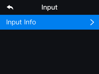
Input

On the main menu, rotate the knob to scroll through the options. Select Input to enter the corresponding menu.

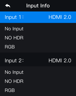
The Input menu displays input information, including the resolution, HDR status, and color space (RGB) of each input source.

If no valid input source is connected to the current input module, the corresponding field displays No Input, and no resolution is shown.

👉

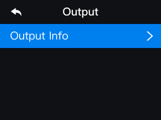
Output On the main menu, rotate the knob to scroll through the options. Select Output to enter the corresponding menu.

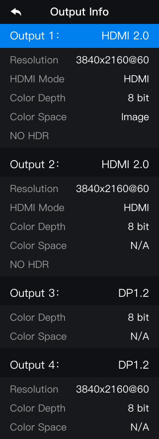
The Output menu displays output information, including the display resolution, HDMI mode, bit depth, color space, and HDR status of each output.

📢  Notes

 FLEX 16pro does not support custom output resolutions.

👉

Preset

On the main menu, rotate the knob to scroll through the options. Select Preset to enter the corresponding menu.

In the** Preset** menu, users can save and load presets. FLEX 16pro supports up to 10 presets.

Use the numeric buttons to select a preset.

Settings

On the main menu, rotate the knob to scroll through the options. Select Settings to enter the corresponding menu.

The Settings menu provides access to system information, language, network settings, key lock, key brightness, factory reset, and other settings.

System Info

Displays the device's model, MCU version, key version, serial number (SN), and IP address.

Language/语言

The system supports two languages: Simplified Chinese and English.

Rotate the knob to select a language, then press the knob to confirm.

Network

Allows you to customize the device's IP address.

Rotate the knob to select a field, then press the knob to edit it. Rotate the knob or use the front-panel numeric buttons to change the value.

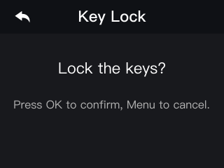
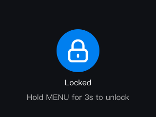
Key Lock

Locks the keys to prevent accidental operation.

Select Confirm in the confirmation dialog to lock the keys. Press MENU to cancel.

When the keys are locked, press and hold MENU for 3 seconds to unlock them.

👉

Key Color

Allows you to adjust the brightness of the front-panel keys from 1% to 100%.

Rotate the knob to adjust the brightness. Press the knob or ENTER to confirm and apply the setting.

Factory Reset

Allows you to restore the device to factory settings.

On the confirmation screen, press the knob to perform a factory reset, or press MENU to cancel.

3.3.2Shortcut Keys

The device's front panel features six function buttons. The selected button is illuminated white.

The following table describes each button's function.

Function ButtonDescription
MENUOpens the main menu or returns to the previous menu.
ENTERConfirms a selection.
SAVEOpens the Save Preset menu.
LOADOpens the Load Scene menu.
SOURCE/
LAYER/

3.3.3Web Control

Web Login

Open a browser and enter the processor's IP address in the address bar (factory default IP: 192.168.1.250). The Web login page will appear. Enter the account and password to log in. Default account: admin, password: (empty by default); as shown below:

Web Operation

After successful login, click the desired scene to recall it. You can also set automatic scene rotation. As shown below:

3.3.4API Control

This system supports HTTP and serial control methods.

HTTP Control Method

HTTP Port: 80.

Keep-alive mode is not supported.

Unless otherwise specified, the POST or GET URL for the interfaces below is: http://host_ip_address/index2.html

Login

Request typePOST
ContentJson: { "Command" : "Login", "UserName" : "Username", "Password" : "MD5 string of password" }
ResponseJson: { "Status" : "Ok"/"Error", "SessionId" : Session ID of this login -- valid when status is ok, "ScreenGroup" : [Screen group permissions, 1 = can operate, 0 = cannot operate], "Message" : "Error message" }
📢  Notes 

The session ID must be saved for subsequent use.

Get Host Scene List

This command retrieves the scene list corresponding to the screen group specified by ScreenGroup.

Request typeGET
Header containssession_id=session id
ContentCommand=GetAllModal&ScreenGroup=Screen group number (1~4)
ResponseJson: { "Status":"Ok"/"Error", "ModalList":["Scene Name", "Scene Name", ...] }

Get Host Scene Thumbnail

Request typeGET
URLhttp://xxx.xxx.xxx.xxx/scene_name.jpg
Header containssession_id=session id
ResponseImage data

Switch Scene

Request typePOST
Header containssession_id=session id
ContentJson: { "Command" : "LoadModal", "ScreenGroup" : Screen group number (1~4), "ModalName" : "Scene Name" }
ResponseJson: { "Status" : "Ok"/"Error", "Message" : "Error message" }

Serial Control Method

Serial Configuration

  • Baud Rate: 9600
  • Parity: None
  • Flow Control: None
  • Data Bits: 8
  • Stop Bits: 1

If using RJ45 network cable to connect to the processor serial port, pin 1 is our TX, pin 2 is our RX, pin 6 is our GND; other pins are disconnected. RJ45 pinout diagram is as follows:

(Refer to original document for RJ45 pinout diagram)

If using DB9 serial cable to connect to the processor serial port, pin 3 is our TX, pin 2 is our RX, pin 5 is our GND. DB9 pin definitions are as follows:

(Refer to original document for DB9 pin definition diagram)

Packet Format

Commands sent from the control system to the device, and responses from the device to the control system, are both encapsulated into data packets. Each packet starts with the $ character and ends with the ^ character, as shown below:

Op indicates the operation command, one character.
Scr indicates the screen group number to be operated, one character.

Format: $ Op Scr DATA ^

The processor control system supports both string commands and hexadecimal commands. The control device can send either string commands or hexadecimal commands to the processor, both of which can be processed. Hexadecimal commands are the ASCII codes of the string.

Serial Commands

Get Host Scene List

Op1
ScrOne byte, value 1 to 4, specifying the screen group number
DATANone
ExamplesGet screen group 1 scenes: $11^ Get screen group 2 scenes: $12^ Get screen group 3 scenes: $13^ Get screen group 4 scenes: $14^
Device ResponseOp: 1 DATA: Multiple scene names separated by spaces (UTF8 format). Example: Scene1 Scene2

Get Current Window List

Op2
ScrOne byte, value 1 to 4, specifying the screen group number.
DATANone
ExamplesGet screen group 1 window list: $21^ Get screen group 2 window list: $22^ Get screen group 3 window list: $23^ Get screen group 4 window list: $24^
Device ResponseOp: 2 DATA: Multiple window information separated by brackets, window info format is [WindowID,Top-left X,Top-left Y,Bottom-right X,Bottom-right Y]. Example: 2[21326,0,0,960,540][25588,960,0,1920,540]...[13336,5760,8100,6720,8640][9651,6720,8100,7680,8640]

Switch Scene

Op3
ScrOne byte, value 1 to 4, specifying the screen group number
DATAScene name (UTF8 format)
ExamplesSwitch screen group 1 to "Scene5": $31Scene5^ Switch screen group 2 to "ab": $32ab^ Switch screen group 3 to "123ab": $33123ab^ Switch screen group 4 to "Scene6a": $34Scene6a^ Scene name "1" code: 24 33 31 31 5E Scene name "2" code: 24 33 31 32 5E Scene name "3" code: 24 33 31 33 5E
Device ResponseOp: 3 DATA: Ok or Error

Open Window with Signal Source

Op4
ScrOne byte, value 1 to 4, specifying the screen group number
DATA[WindowID][Input Slot 1-16][Input Port 1-8][Top-left X,Top-left Y,Bottom-right X,Bottom-right Y] Window ID must be an integer >=1, with uniqueness; multiple windows cannot have duplicate IDs.
ExamplesOpen input slot 2 port 3 on group 1, window ID=2, coords 1920,1080,3840,2160: $41[2][2][3][1920,1080,3840,2160]^ Hex code: 24 34 31 5B 32 5D 5B 32 5D 5B 33 5D 5B 31 39 32 30 2C 31 30 38 30 2C 33 38 34 30 2C 32 31 36 30 5D 5E
Device ResponseOp: 4 DATA: Ok or Error

Switch Window Signal Source

Op5
ScrOne byte, value 1 to 4, specifying the screen group number
DATA[WindowID][Input Slot 1-16][Input Port 1-8] Window ID can be obtained via Get Current Window List interface.
ExamplesSwitch input slot 2 port 3 to window ID 21326 on group 1: $51[21326][2][3]^ Hex code: 24 35 31 5B 32 31 33 32 36 5D 5B 32 5D 5B 33 5D 5E
Device ResponseOp: 5 DATA: Ok or Error

Get Processor IP

Op6
ScrNone
DATANone
Example$6^
Device ResponseOp: 6 DATA: Processor IP. Example: IP:[192.168.1.250]

Set Processor IP Address

Op7
ScrNone
DATAIP address
ExampleSet processor IP address to 192.168.1.200: $7192.168.1.200^
Device ResponseOp: 7 DATA: Ok or Error

Reset Processor

Op8
ScrNone
DATANone
Example$8^
Device ResponseOp: 8 DATA: Ok or Error, device restarts after successful reset

Switch Audio Channel

Op9
ScrNone
DATA[Input Slot 1-16][Input Port 1-8] To close audio input, set both input slot and input port to 0.
ExamplesSwitch to slot 2 port 3: $9[2][3]^ Close audio input: $9[0][0]^ Switch to slot 2 port 3 hex code: 24 39 5B 32 5D 5B 33 5D 5E Close audio hex code: 24 39 5B 30 5D 5B 30 5D 5E
Device ResponseOp: 9 DATA: Ok or Error

Close Window

Op0
ScrOne byte, value 1 to 4, specifying the screen group number
DATA[WindowID] To close all windows in current group, set WindowID to 0.
ExamplesClose group 2 window ID 1: $02[1]^ Close group 1 all windows: $01[0]^ Close group 2 window ID 1 hex: 24 30 32 5B 31 5D 5E Close group 1 all windows hex: 24 30 31 5B 30 5D 5E
Device ResponseOp: 0 DATA: Ok or Error

Move Window

Opa
ScrOne byte, value 1 to 4, specifying the screen group number
DATA[WindowID][Top-left X,Top-left Y,Bottom-right X,Bottom-right Y] Window ID can be obtained via Get Current Window List interface. 0509 point-to-point mode does not support window operations.
ExampleMove group 1 window ID 1 to 1920,1080,3840,2160: $a1[1][1920,1080,3840,2160]^ Hex code: 24 61 31 5B 31 5D 5B 31 39 32 30 2C 31 30 38 30 2C 33 38 34 30 2C 32 31 36 30 5D 5E
Device ResponseOp: a DATA: Ok or Error

3.5Revision History

VersionDateDescriptionAuthor
V1.02026-11-18First release.Alyn

3.6Technical Support

3.7Declarations

FCC/Warranty

Federal Communications Commission (FCC) Statement

This equipment has been tested and found to comply with the limits for a class A digital device, pursuant to Part 15 of the FCC rules. These limits are designed to provide reasonable protection against harmful interference when the equipment is operated in a commercial environment. This equipment generates, uses, and can radiate radio frequency energy and, if not installed and used in accordance with the instruction manual, may cause harmful interference to radio communications. Operation of this equipment in a residential area may cause harmful interference, in which case the user will be responsible for correcting any interference.

Guarantee and Compensation

RGBlink provides a guarantee relating to perfect manufacturing as part of the legally stipulated terms of guarantee. On receipt, the purchaser must immediately inspect all delivered goods for damage incurred during transport, as well as for material and manufacturing faults. RGBlink must be informed immediately in writing of any complains.

The period of guarantee begins on the date of transfer of risks, in the case of special systems and software on the date of commissioning, at latest 30 days after the transfer of risks. In the event of justified notice of compliant, RGBlink can repair the fault or provide a replacement at its own discretion within an appropriate period. If this measure proves to be impossible or unsuccessful, the purchaser can demand a reduction in the purchase price or cancellation of the contract. All other claims, in particular those relating to compensation for direct or indirect damage, and also damage attributed to the operation of software as well as to other service provided by RGBlink, being a component of the system or independent service, will be deemed invalid provided the damage is not proven to be attributed to the absence of properties guaranteed in writing or due to the intent or gross negligence or part of RGBlink.

If the purchaser or a third party carries out modifications or repairs on goods delivered by RGBlink, or if the goods are handled incorrectly, in particular if the systems are commissioned operated incorrectly or if, after the transfer of risks, the goods are subject to influences not agreed upon in the contract, all guarantee claims of the purchaser will be rendered invalid. Not included in the guarantee coverage are system failures which are attributed to programs or special electronic circuitry provided by the purchaser, e.g. interfaces. Normal wear as well as normal maintenance are not subject to the guarantee provided by RGBlink either.

The environmental conditions as well as the servicing and maintenance regulations specified in this manual must be complied with by the customer.

Operators Safety Summary

The general safety information in this summary is for operating personnel.

Do Not Remove Covers or Panels

There are no user-serviceable parts within the unit. Removal of the top cover will expose dangerous voltages. To avoid personal injury, do not remove the top cover. Do not operate the unit without the cover installed.

Power Source

This product is intended to operate from a power source that will not apply more than 230 volts rms between the supply conductors or between both supply conductor and ground. A protective ground connection by way of grounding conductor in the power cord is essential for safe operation.

Grounding the Product

This product is grounded through the grounding conductor of the power cord. To avoid electrical shock, plug the power cord into a properly wired receptacle before connecting to the product input or output terminals. A protective-ground connection by way of the grounding conductor in the power cord is essential for safe operation.

Use the Proper Power Cord

Use only the power cord and connector specified for your product. Use only a power cord that is in good condition. Refer cord and connector changes to qualified service personnel.

Use the Proper Fuse

To avoid fire hazard, use only the fuse having identical type, voltage rating, and current rating characteristics. Refer fuse replacement to qualified service personnel.

Do Not Operate in Explosive Atmospheres

To avoid explosion, do not operate this product in an explosive atmosphere.

Installation Safety Summary

Safety Precautions

For all device installation procedures, please observe the following important safety and handling rules to avoid damage to yourself and the equipment.

To protect users from electric shock, ensure that the chassis connects to earth via the ground wire provided in the AC power Cord.

The AC Socket-outlet should be installed near the equipment and be easily accessible.

Unpacking and Inspection

Before opening device shipping box, inspect it for damage. If you find any damage, notify the shipping carrier immediately for all claims adjustments. As you open the box, compare its contents against the packing slip. If you find any shortages, contact your sales representative.

Once you have removed all the components from their packaging and checked that all the listed components are present, visually inspect the system to ensure there was no damage during shipping. If there is damage, notify the shipping carrier immediately for all claims adjustments.

Site Preparation

The environment in which you install your device should be clean, properly lit, free from static, and have adequate power, ventilation, and space for all components.

About Us / Find Support

Xiamen RGBlink Science & Technology Co., Ltd. designs and manufactures professional video processing, switching, streaming and LED display control products for live events, broadcast, education and fixed installations.

Need help?

Choose one of the following support options:

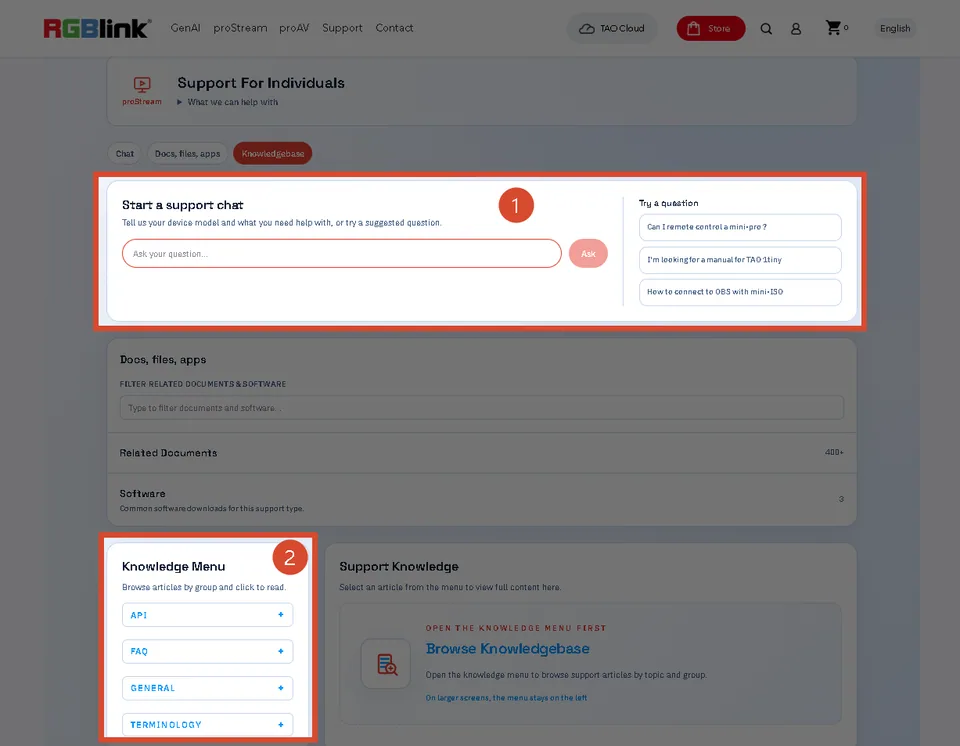
  • AI Support Search (Recommended): Visit Support > Support proStream/proAV/proEvents on the RGBlink official website and ask the RGBlink AI Bot for quick answers.
  • FAQs: Visit Support > Support proStream/proAV/proEvents on the RGBlink official website and browse Knowledge Menu > FAQ.
  • Contact Technical Support: Visit the Technical Support page of this manual or the RGBlink official website for our contact details.

Document image

RGBlink

www.rgblink.com

© Copyright Xiamen RGBlink Science & Technology Co Ltd