Export PDF

RGBlink
Q16pro Gen2

User Manual

Q16pro Gen2

Q16pro-Gen2-manual

191828

RGBlink

www.rgblink.com

November 2026

1Q16pro Gen2 - This Specification

🔔  Specifications are current at the time of publication and subject to change without notice.  

This chapter provides the technical specifications of RGBlink Q16pro Gen2, including specifications for the models and the supported modules.

Refer to the corresponding model or module for detailed specifications.

1.1Notes and Cautions

Notes for Battery

The general safety information in this summary is for operating personnel.

  • Do Not Remove Covers or Panels 一 There are no user-serviceable parts within the unit. Removal of the top cover will expose dangerous voltages. To avoid personal injury, do not remove the top cover. Do not operate the unit without the cover installed.
  • Power Source 一 This product is intended to operate from a power source that will not apply more than 230 volts rms between the supply conductors or between both supply conductor and ground. A protective ground connection by way of grounding conductor in the power cord is essential for safe operation.
  • Grounding the Product 一 This product is grounded through the grounding conductor of the power cord. To avoid electrical shock, plug the power cord into a properly wired receptacle before connecting to the product input or output terminals. A protective-ground connection by way of the grounding conductor in the power cord is essential for safe operation.
  • Use the Proper Power Cord 一 Use only the power cord and connector specified for your product. Use only a power cord that is in good condition. Refer cord and connector changes to qualified service personnel.
  • Use the Proper Fuse 一 To avoid fire hazard, use only the fuse having identical type, voltage rating, and current rating characteristics. Refer fuse replacement to qualified service personnel.
  • Do Not Operate in Explosive Atmospheres 一 To avoid explosion, do not operate this product in an explosive atmosphere.

Notes for Installation

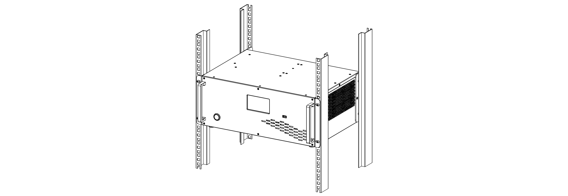
When the product needs to be installed on the rack, 4 screws at least M5*12 should be used to fix it. The rack for installation shall bear at least 42kg weight.

  • Safety Precautions 一 To protect users from electric shock, ensure that the chassis connects to earth via the ground wire provided in the AC power Cord. The AC Socket-outlet should be installed near the equipment and be easily accessible.
  • Unpacking and Inspection 一 Before opening device shipping box, inspect it for damage. If you find any damage, notify the shipping carrier immediately for all claims adjustments. As you open the box, compare its contents against the packing slip. If you find any shortages, contact your sales representative.
  • Site Preparation 一 The environment in which you install your device should be clean, properly lit, free from static, and have adequate power, ventilation, and space for all components.
  • Mechanical Loading 一 Mounting of the device in the rack should be such that a
  • hazardous condition is not achieved due to uneven mechanical loading.

1Product Overview

Q16pro Gen2 adopts a high-performance video image processing system with a pure hardware wire-speed processing architecture, which is suitable for education and scientific research, government announcements, information publishing, administrative management, military command, exhibitions, security monitoring, commercial sales and other industries.

The modular input and output card structure is adopted, and the arbitrary mixing function of the input card is realized at the same time. Not only can it easily access the common HDMI/DVI/SDI/IP/AUDIO/DANTE/HDBASET and other multiple signals, but also support DP 1.2, HDMI 2.0 and other ultra-high resolution 4K/8K signal input and output, easily realize 4K multi-screen point-to-point splicing.

2Features

2.1 Input and Output

9 types of pluggable input modules, user configurable
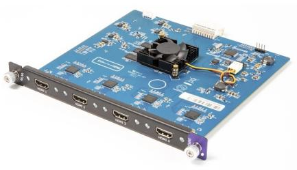
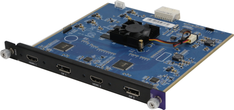
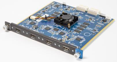
  • Quad HDMI 2.0 Input Module
  • Single 4K60 Input Module
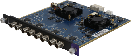
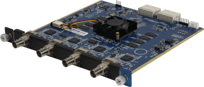
  • Quad 3G SDI (LOOP) Input Module
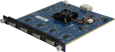
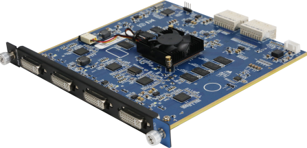
  • Quad DVI Input Module
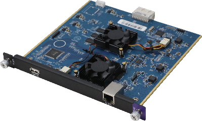
  • Single IP Input Module
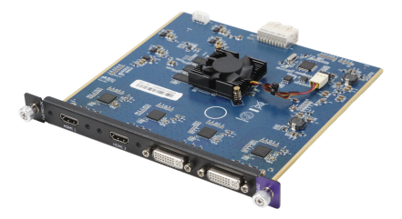
  • Dual HDMI 1.3 & Dual DVI Input Module
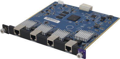
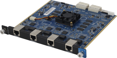
  • Quad HDBaseT Input Module
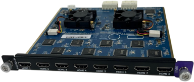
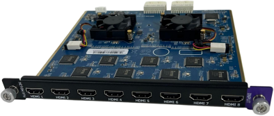
  • 8-CH HDMI 1.3 Input Module(dedicated for use with 8U, coming soon)
  • Dual 4K60 Input Module (dedicated for use with 8U, coming soon)
13 types of pluggable output modules, user configurable
  • Quad HDMI 1.3 Output Module
  • 16-layer Quad HDMI 1.3 Output Module
  • Quad 3G SDI Output Module
  • 16-layer Quad 3G SDI Output Module
  • Quad DVI Output Module
  • 16-layer Quad DVI Output Module
  • Dual HDMI 2.0 Output Module
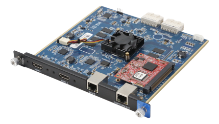
  • Dual HDMI 1.3 Output Module with Dante
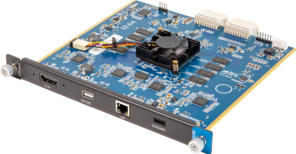
  • Streaming Output Module
  • Quad HDBaseT Output Module
  • 16-layer Quad HDBaseT Output Module
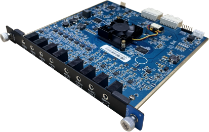
  • Quad Input & Quad Output Analog Audio Module
  • 8-CH HDMI 1.3 Output Module (dedicated for use with 8U, coming soon)
Pluggable communication module
  • Communication Module with PVW
Power module
  • 2U and above support redundant power module

2.2 Key Features

  • Each module support 16 screens spanning the output port without occupying layers
  • 12 bit input and output, RGB 4: 4: 4 color space
  • Triple independent OSD rolling subtitles
  • Multi-window monitoring for inputs
  • i-signal output supported
  • LOGO overlay
  • Seamless switch between signals and scenes
  • Dual power module backup

2.3 Device Controls

XPOSE Software Control
  • Q16pro Gen2 can be connected to the XPOSE software for smart and convenient device management.
Cascading Control via Ethernet
  • The Ethernet control port supports UDP protocol and star topology. Can achieve device cascading and communication on the same LAN.

3Appearance

This chapter provides illustrations and descriptions of the Q16pro Gen2 front and rear panels.

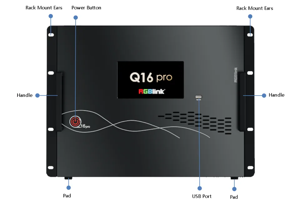
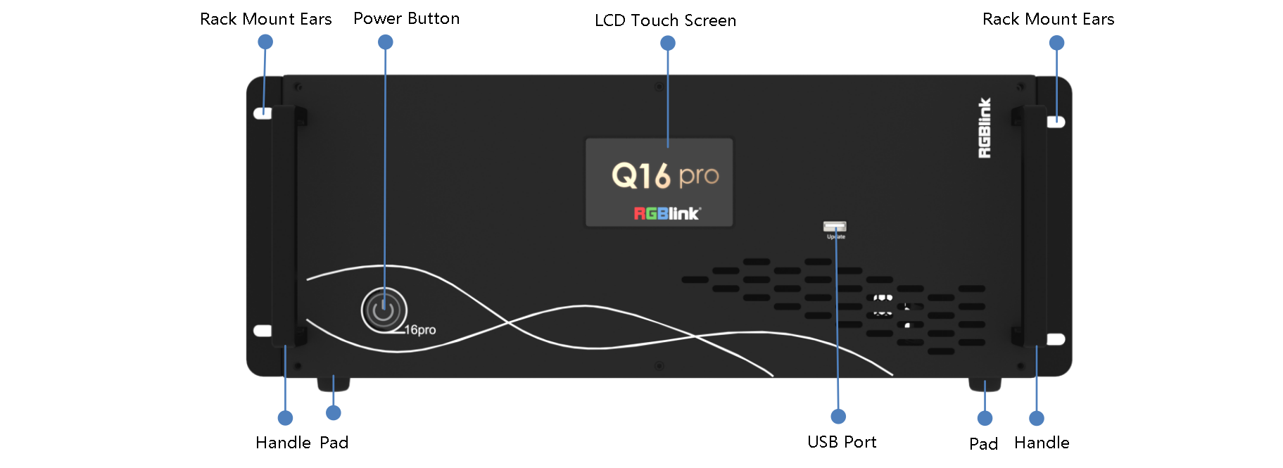
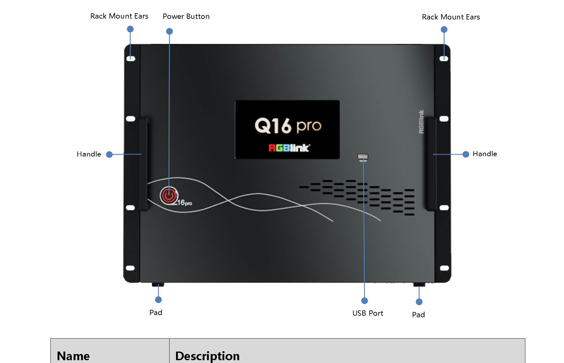
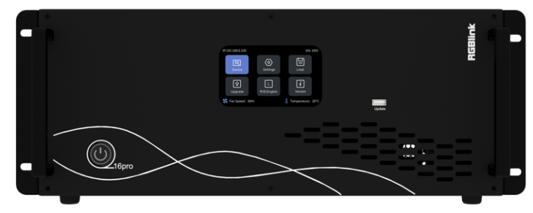
3.1Front Panel

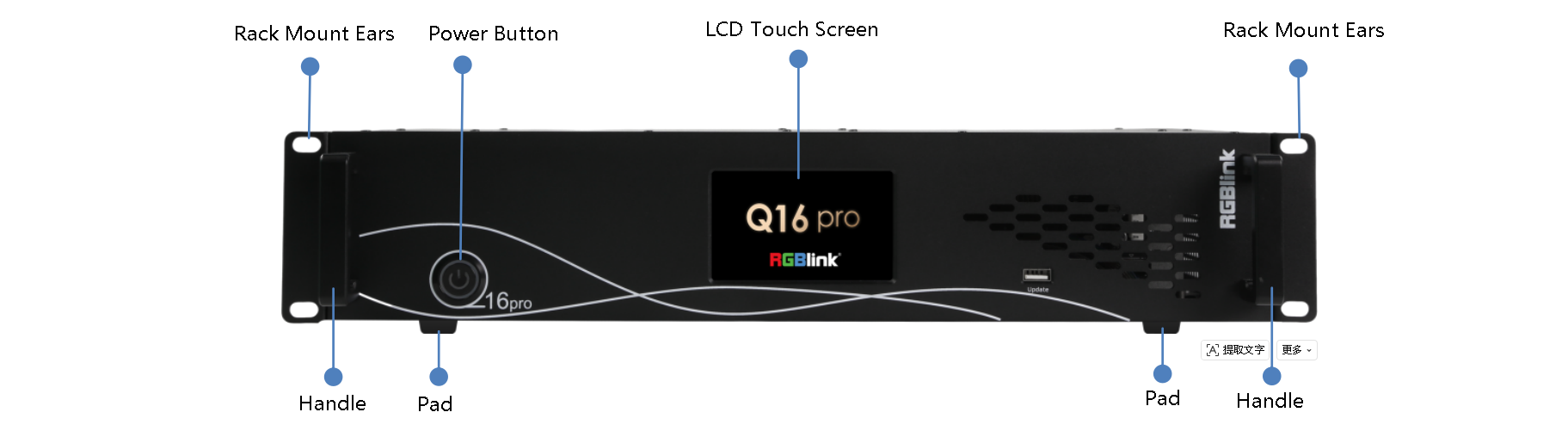
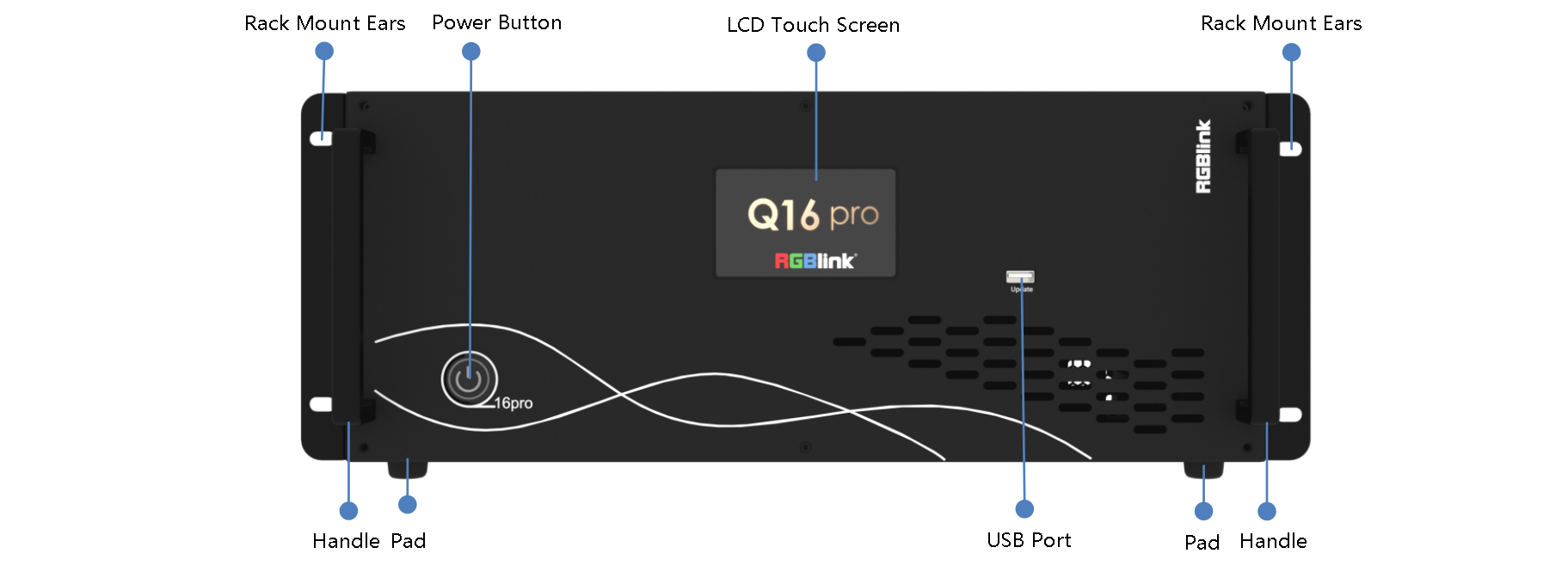
ModelIllustrations
Q16pro Gen2 2U
Q16pro Gen2 4U
Q16pro Gen2 8UDocument image
NameDescription
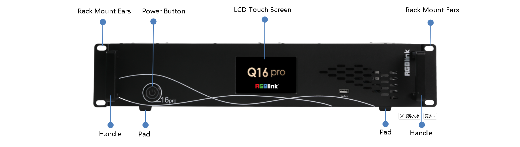
LCD Touch Screen+ Display current status of the device. + For menu operation.
Power Button+ Press the button to power on or power off the device. + Button light turns red when powered on.
USB PortUsed for device upgrade.
HandlesFor carrying device.
Rack Mount EarsUse with the load-bearing screws to fix device on the rack.
PadSupport device and enhance shock absorption capability.

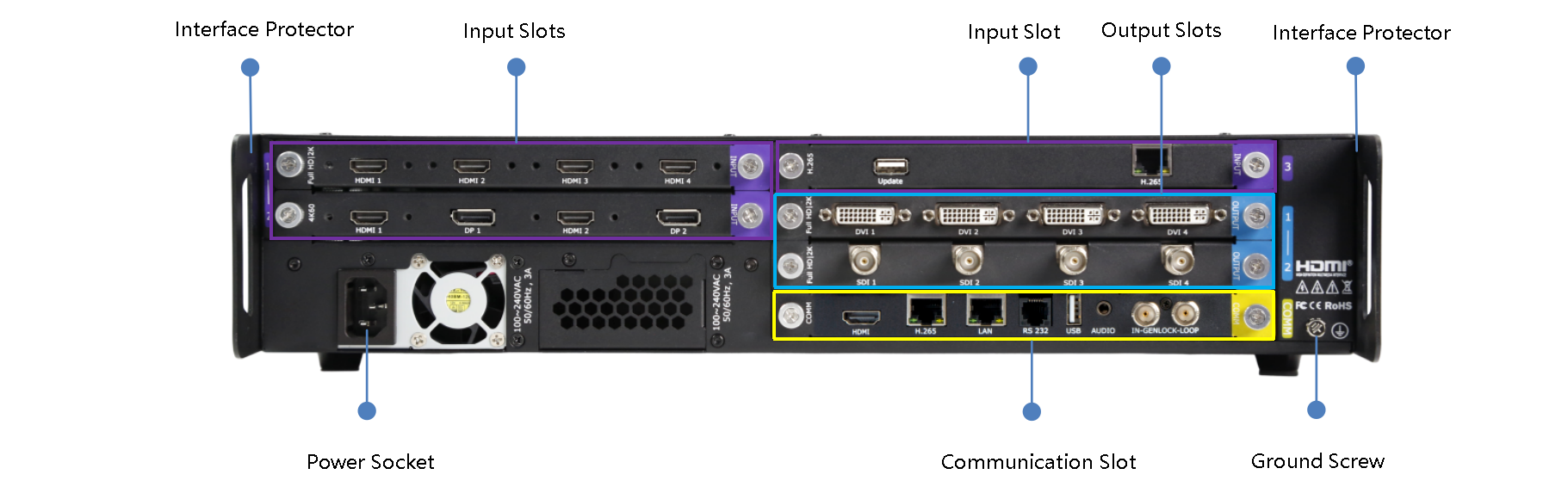
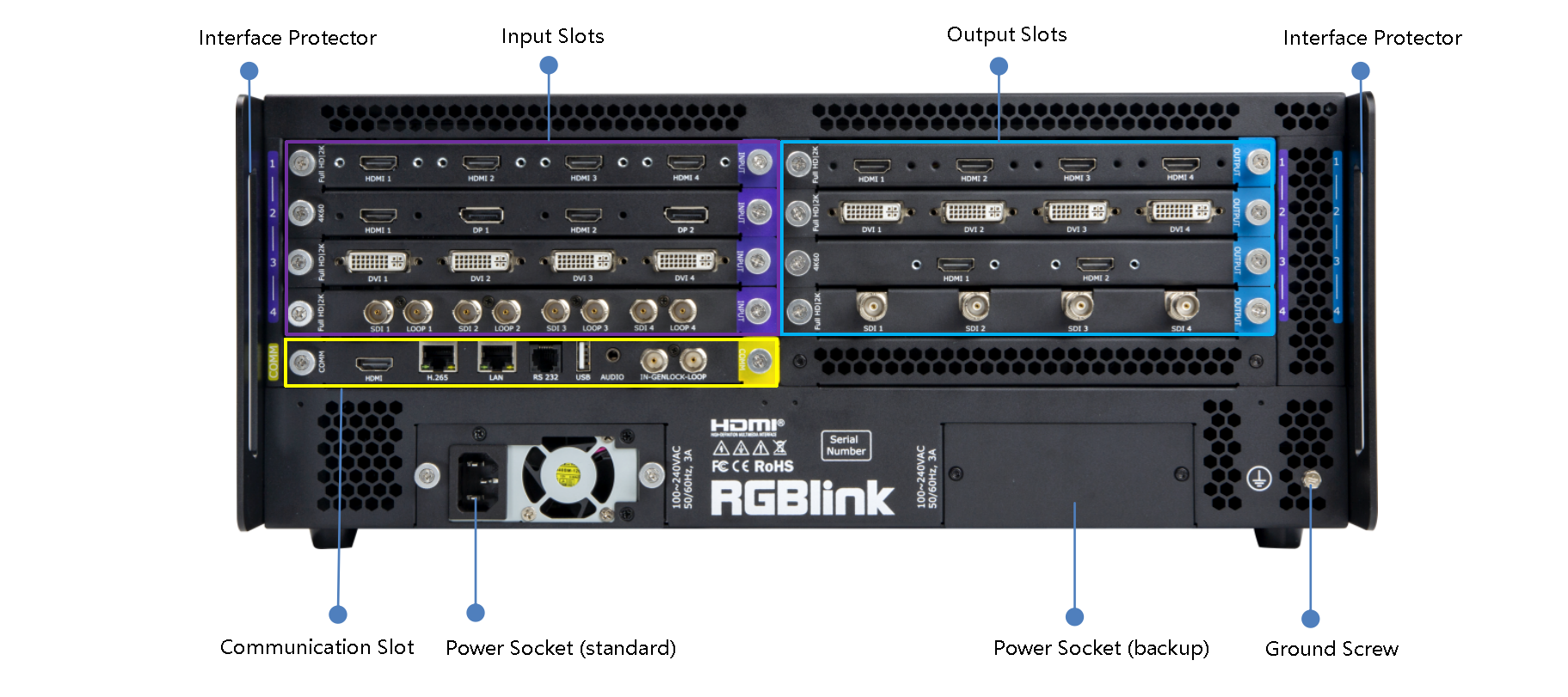
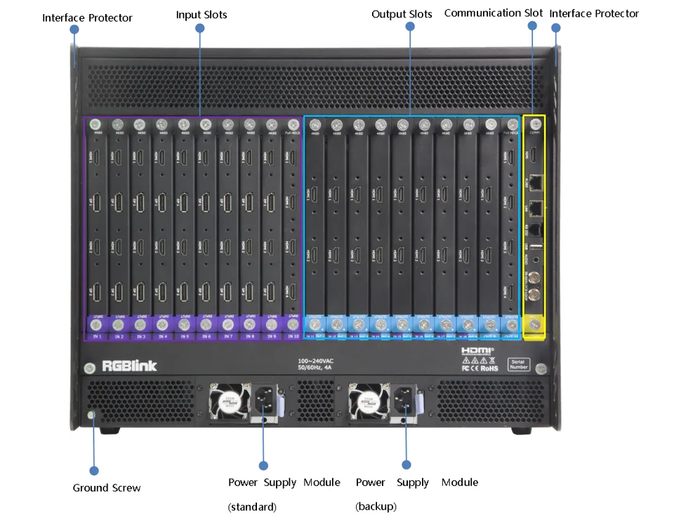
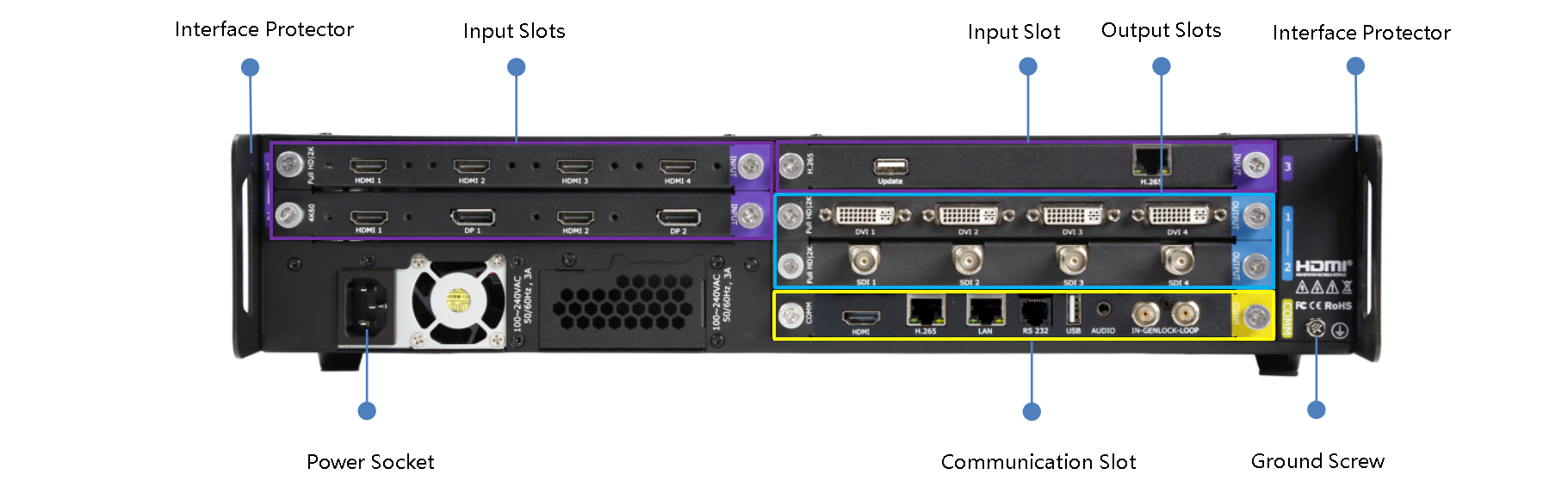
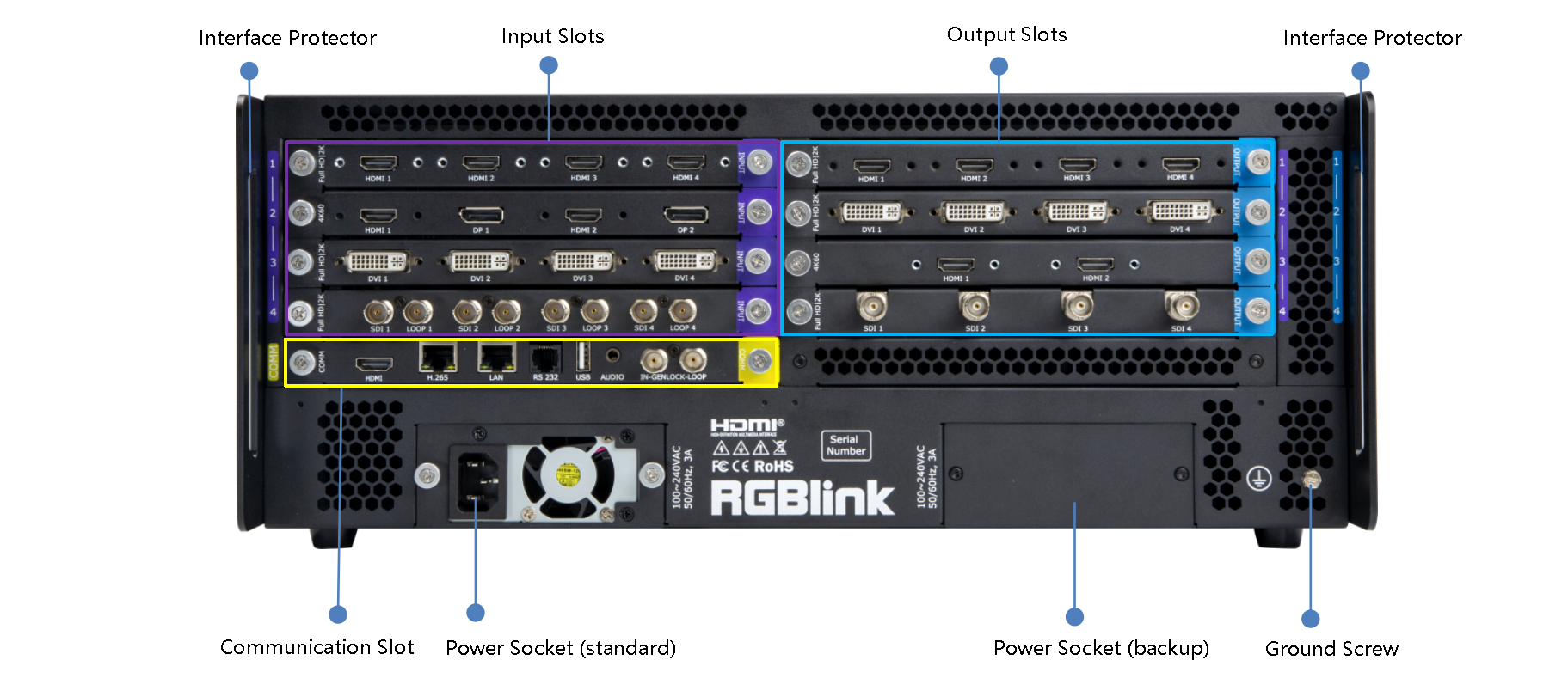
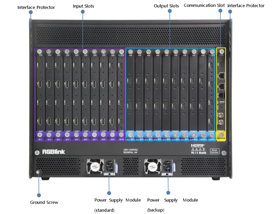
3.2Rear Panel

ModelIllustrations
Q16pro Gen2 2U
Q16pro Gen2 4U
Q16pro Gen2 8UDocument image
NameDescription
Input Slots+ Support quad HDMI 1.3, quad DVI, quad 3G SDI (LOOP), dual HDMI 2.0 & dual DP 1.2, single IP, dual HDMI 1.3 & dual DVI, quad HDBaseT input module + Purple tip indicates input
Output Slots+ Support quad HDMI 1.3, quad 3G SDI, quad DVI, dual HDMI 2.0, dual HDMI 1.3 with Dante, quad HDBaseT, streaming output module, quad input & quad output analog audio module + Support input modules + Blue tip indicates output
Communication Slot+ Communication module with PVW - 1 × PVW (HDMI port) for multiwindow monitoring - 1 × IP (H.265 port) for remote control and IP echo - 1 × LAN for software control and device upgrade - 1 × RS232 serial port for software control - 1 × USB port for device upgrade - 1 × TRS audio jack for monitoring - 1 × INGENLOCKLOOP for connecting to a synchronization signal + Yellow tip indicates communication
Power SocketIEC power socket (1 * standard & 1* backup)
Interface ProtectorUsed to pull out device, fix cables and protect interfaces from collision
Ground ScrewIncrease the safety and reliability, and avoid accidents such as fire and explosion caused by static electricity.

4Power Consumption

ModelPower Consumption
2U (Communication Module with PVW Included)30 W
4U (Communication Module with PVW Included)36 W
8U (Communication Module with PVW Included)50 W

5Dimensions

ItemDimension
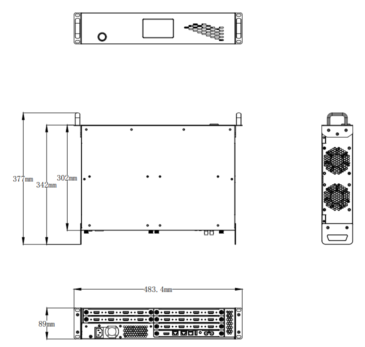
Q16pro Gen2 2U483.4mm×377mm×89mm
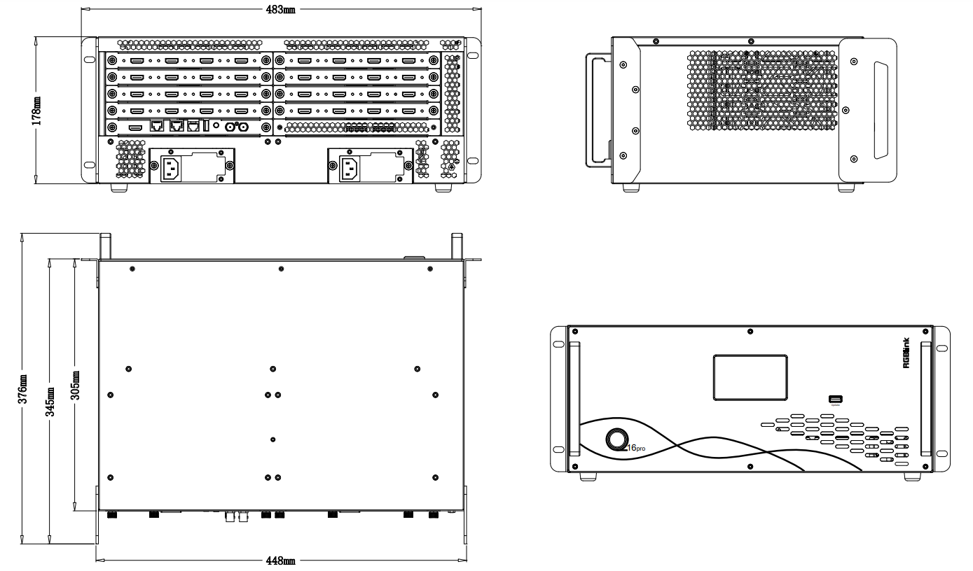
Q16pro Gen2 4U483mm×376mm×178mm
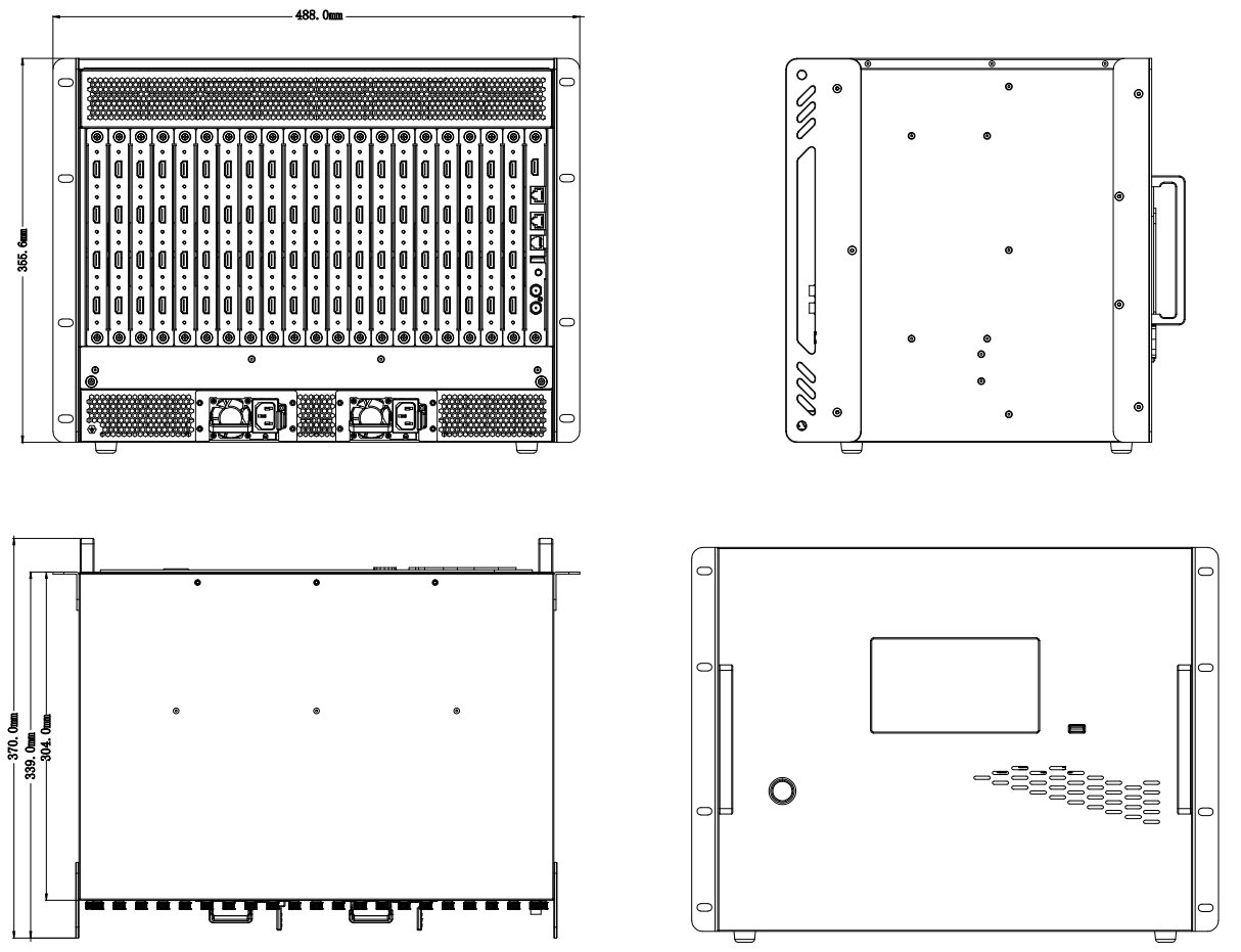
Q16pro Gen2 8U488mm×370mm×355.6mm
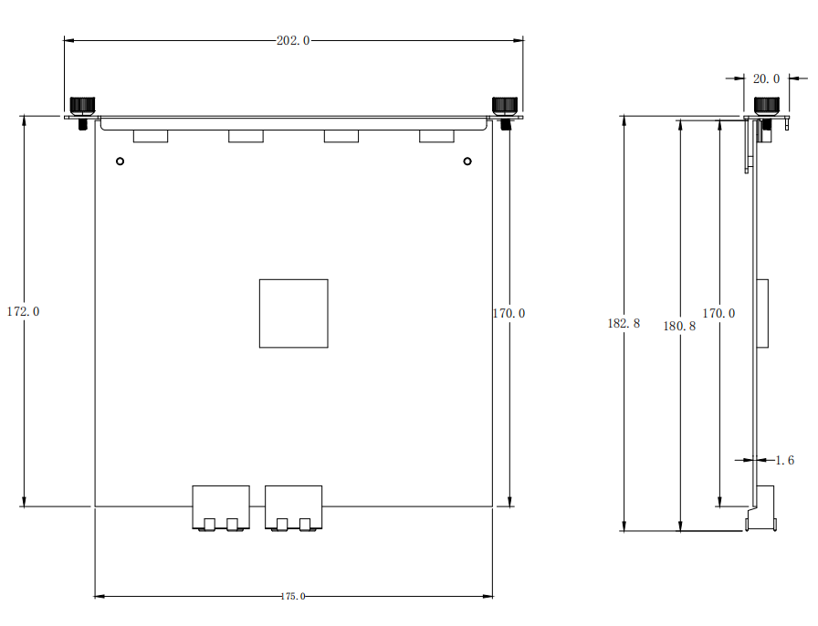
Module202mm×190.8mm×20mm

6Product Specification

Overview

ModelQ16pro Gen2 2UQ16pro Gen2 4UQ16pro Gen2 8U
Specification2U4U8U
Input Slots (max)3818
Output Slots (max)2410
Shared Slotsno supportOutput slot No. 1-4Output slot No. 1-8

Physical

ModelQ16pro Gen2 2UQ16pro Gen2 4UQ16pro Gen2 8U
Net Dimension483.4×377×89mm483.4×376×178mm488×370×355.6mm
Package Dimension630×585×250mm645×525×295mm585×460×520mm
Net Weight5.83KG7.54kg13.72kg
Package Weight9.25kg11.47kg18.42kg
Module Weight
Input ModuleWeightInput ModuleWeight
Quad HDMI 2.00.27kgQuad DVI0.27kg
**Dual HDMI 1.3 & Dual DVI **0.27kgQuad 3G SDI(LOOP)0.40kg
Dual HDMI 2.0 & Dual DP 1.20.27kg**Single IP **0.26kg
Quad HDBaseT0.30kg8-CH HDMI 1.3 (8U)0.3kg
Output ModuleWeightOutput ModuleWeight
**Quad HDMI 1.3 **0.28kgQuad DVI0.28kg
**Quad 3G SDI **0.34kgDual HDMI 2.00.26kg
Analog Audio Module0.30kgStreaming Module0.28kg
Quad HDBaseT0.30kgDual HDMI 1.3 with Dante0.31kg
16-Layer Quad HDMI 1.30.28kg16-Layer Quad DVI0.28kg
16-Layer Quad 3G SDI0.34kg16-Layer Quad HDBaseT0.30kg
8-CH HDMI 1.3 (8U)0.3kg//
OthersWeight
300W Redundant Power0.74kg
Communication Module with PVW0.30kg
550W Redundant PowerTBC

Supported Standards

ItemDescription
SDISD/HD/3G
HDMI2.0
**DVI **1.0
DP1.2
H.265H.265
HDBaseT1.0

Power

ItemDescription
Input VoltageAC 100V-240V, 50/60Hz (2U and above support dual PSU.)

Working Environment

ItemDescription
Temperature-20℃-60℃
Humidity15%-85%, RH

Storage Environment

ItemDescription
Temperature-20℃-60℃
Humidity5%-85%, RH

7Module Specification

This chapter provides detailed specifications for the modules supported by Q16pro Gen2.

7.1Input Module

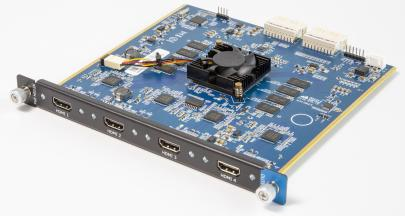
Input Module 1: Quad HDMI 2.0 Input Module

IllustrationKey Features
+ Fully modular architecture + Support 4 HDMI2.0 (with HDCP) inputs + Input resolution up to 3840×2160@60Hz + EDID management + Support hot swap
ItemDescription
ConnectorsInput4×HDMI-A
PerformanceResolutionSMPTE 3840×2160p@30/50/59.94/60; 1920×1080p@24/25/29.97/30/50/59.94/60; 1920×1080i@50/59.94/60; 1280×720p@23.98/24/25/29.97/30/50/59.94/60; 720×480p@60; 720×576p@50
VESA 3840×2160p@30/50/59.94/60; 1920×1200p@60; 1920×1200p@60; 1920×1080p@60; 1680×1050p@60; 1400×1050p@60; 1440×900p@60; 1366×768p@60; 1360×768p@60; 1280×1024p@60/75/85; 1280×800p@60; 1024×768p@60/75/85
Max Width/HeightMax width: 3840 (3840×2160@60) Max height: 2160 (3840×2160@60)
Power Consumption8.5W
Frame Rate≤240Hz
Total Pixel Capacity≥2.35M (Million)
Transmission Rate≤20Gbps
Transmission Cable Length≤10m
PhysicalWeight0.27kg
Dimension202mm×190.8mm×20mm
Order CodeProduct Code790-1002-10-1

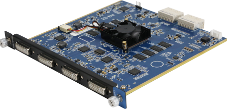
Input Module 2: Quad DVI Input Module

IllustrationKey Features
+ Fully modular architecture + Quad standard DVI input signals + Input resolution up to 2048×1080@60Hz + EDID management + Support hot swap
ItemDescription
ConnectorsInput4×DVI-I
PerformanceResolutionSMPTE 1920×1080p@24/25/29.97/30/50/59.94/60; 1920×1080i@50/59.94/60; 1280×720p@23.98/24/25/29.97/30/50/59.94/60; 720×576p@50; 720×480p@60; Customized resolution
VESA 1920×1200p@60; 1920×1080p@60; 1680×1050p@60; 1400×1050p@60; 1440×900p@60; 1366×768p@60; 1360×768p@60; 1280×1024p@60/75/85; 1280×800p@60; 1024×768p@60/75/85; Customized resolution
Customized Resolutions1872×1152@60; 1920×1152@60; 1840×960@60; 1536×960@60;
Note: Resolutions listed above have been tested already, for other Customized resolutions not mentioned, please refer to the actual use.
Max Width/Height+ Max width: 2048 (2048×1080@60) + Max height: 1200 (1920×1200@60)
Power Consumption7W
Frame Rate≤240Hz
Total Pixel Capacity≥2.35M (Million)
EDID ManagementSupport DVI 1.0 / HDMI 1.3
HDCPHDCP 1.x compliant
Transmission Rate≤20Gbps
Transmission Cable Length≤100m
PhysicalWeight0.27kg
Dimension202mm×190.8mm×20mm
Order CodeProduct Code790-1002-35-1

Input Module 3: Dual HDMI 1.3 & Dual DVI Input Module

IllustrationKey Features
+ Choose 1 channel from dual HDMI 1.3 & dual DVI Input ports + Fully modular architecture + Support HDMI (with HDCP) inputs + Input resolution up to 2048×1080@60Hz + EDID management + Support hot swap
ItemDescription
ConnectorsInput2×HDMI-A; 2×DVI-I
PerformanceResolutionSMPTE 1920×1080p@24/25/29.97/30/50/59.94/60; 1920×1080i@50/59.94/60; 1280×720p@23.98/24/25/29.97/30/50/59.94/60; 720×576p@50; 720×480p@60; Customized resolution
VESA 1920×1200p@60; 1920×1080p@60; 1680×1050p@60; 1400×1050p@60; 1440×900p@60; 1366×768p@60; 1360×768p@60; 1280×1024p@60/75/85; 1280×800p@60; 1024×768p@60/75/85; Customized resolution
Customized Resolutions1872×1152@60; 1920×1152@60; 1840×960@60; 1536×960@60
Note: Resolutions listed above have been tested already, for other Customized resolutions not mentioned, please refer to the actual use.
Max Width/Height+ Max width: 2048 (2048×1080@60) + Max height: 1200 (1920×1200@60)
Power Consumption7W
Frame Rate≤240Hz
Total Pixel Capacity≥2.35M (Million)
EDID ManagementSupport DVI 1.0 / HDMI 1.3
HDCPHDCP 1.x compliant
Transmission Rate≤20Gbps
Transmission Cable Length≤100m
PhysicalWeight0.27kg
Dimension202mm×190.8mm×20mm
Order CodeProduct Code790-1002-44-1

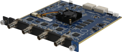
Input Module 4: Quad 3G SDI (LOOP) Input Module

IllustrationKey Features
+ Fully modular architecture + Input resolution up to 1920×1080@60Hz + Support I/P signal input + Support hot swap
ItemDescription
ConnectorsInput8×BNC (4 IN; 4 LOOP)
PerformanceResolutionSMPTE 1920×1080p@23.98/24/25/29.97/30/50/59.94/60; 1920×1080i@50/59.94/60; 1280×720p@50/59.94/60; 576i@50; 720×480p@60; 480i@60
VESA 1920×1080p@60
Standard+ Support ST-424 (3G), ST292 (HD) standard video inputs. + Support 3G-Level A/Level B (DS mode).
Power Consumption13.5W
Frame Rate≤240Hz
Total Pixel Capacity≥2.07M (Million)
Interlaced Signal InputsSupport
Transmission Rate≤20Gbps
Transmission Cable Length≤100m
PhysicalWeight0.40kg
Dimension202mm×190.8mm×20mm
Order CodeProduct Code790-1002-34-1

Input Module 5: Single 4K60 Input Module

IllustrationKey Features
+ Fully modular architecture + 2×HDMI 2.0 and 2×DP1.2 interface + Support HDMI(with HDCP) inputs + Input resolution up to 3840×2160@60Hz + EDID management + Support hot swap + Choose one 4K60 input signal or two 4K30 input signals to use
ItemDescription
ConnectorsInput2×HDMI-A; 2×DP
PerformanceResolutionSMPTE 3840×2160p@25/30/50/60; 3840×1080p@30/60; 1920×1080p@23.98/24/25/29.97/30/50/59.94/60; 1280×720p@50/59.94/60; 720×576p@50; 576i@50; 720×480p@60; 480i@60; Customized resolution
VESA 3840×2160p@25/30/50/60; 2560×1600p@60; 2560×1440p@60; 2048×1152p@60; 1920×1200p@60; 1920×1080p@60; 1680×1050p@60; 1366×768p@60; 1400×1050p@60; 1440×900p@60; 1366×768p@60; 1360×768p@60; 1280×1024p@60/75/85; 1280×800p@60; 1024×768p@60/75/85; 800×600p@60/75/85; 640×480p@60/75/85
Max Width/Height+ Max width: 3840 + Max height: 2160
Power Consumption8.8W
Frame Rate≤240Hz
Total Pixel Capacity≥8.29M (Million)
EDID ManagementSupport HDMI 2.0 / HDMI 1.4 / HDMI 1.3
HDCPHDCP 2.2 compliant
Transmission Rate≤20Gbps
Transmission Cable Length≤100m
PhysicalWeight0.27kg
Dimension202mm×190.8mm×20mm
Order CodeProduct Code790-1002-33-1

Input Module 6: Single IP Input Module

IllustrationKey Features
+ Fully modular architecture + Max support 16-channel 540p60 decoding + Support RTSP/RTMP network protocol + Support NDI protocol transmission + Support hot swap
ItemDescription
ConnectorsInput1×USB-A; 1×RJ45 Gigabit Network Port
PerformanceResolutionSMPTE 2160p@30/60; 1080p@30/50/60; 720p@30/50/60
Network Protocol+ RTSP + RTMP + NDI 6
Decoding Standard+ H.265 Main Profile Level 5.1 + H.264 Baseline/Main/High Profile Level 5.0 + NDI, HX + NDI, HX2, NDI, HX3 + Full NDI (comming soon)
Decoding Resolution+ 1-channel: 3840×2160@60 + 4-channel: 1920×1080@60 + 16-channel: 960×540@60
Single Card Decoding Capability+ 1-channel: 3840×2160@60fps + 4-channel: 3840×2160@30fps ; 1920×1080@60fps + 16-channel: 1920×1080@30fps
Transmission Cable Length≤100m
Power Consumption14.5W
PhysicalWeight0.28kg
Dimension202mm×190.8mm×20mm
Order CodeProduct Code790-1002-32-1

Input Module 7: Quad HDBaseT Input Module

IllustrationKey Features
+ Fully modular architecture + Resolution up to 1920×1080@60 + Extend up to 100m + Uncompressed audio and video transmission + Support hot swap
ItemDescription
ConnectorsInput4×RJ45
PerformanceResolutionSMPTE 2160p@30/60; 1080p@30/50/60; 720p@30/50/60
VESA 1920×1080@60; 1600×1200@60; 1280×1024@60; 1280×768@60; 1024×768@60; 800×600@60
Transmission Rate≤20Gbps
Transmission Cable Length≤100m
Power Consumption22.8W
PhysicalWeight0.30kg
Dimension202mm×190.8mm×20mm
Order CodeProduct Code790-1002-46-1

Input Module 8: 8-CH HDMI 1.3 Input Module (decicated for use with 8U, coming soon)

IllustrationKey Features
+ Support embedded audio + Support 8 HDMI 1.3 (with HDCP) inputs + Input resolution up to 1920×1080@60Hz + EDID management
ItemDescription
ConnectorsInput8×HDMI-A
PerformanceResolutionSMPTE 1920×1080p@24/25/29.97/30/50/59.94/60; 1920×1080i@50/59.94/60; 1280×720p@23.98/24/25/29.97/30/50/59.94/60; 720×576p@50; 720×480p@60
VESA 1920×1080p@60; 1680×1050p@60; 1400×1050p@60; 1440×900p@60; 1366×768p@60; 1360×768p@60; 1360×768p@60; 1280×1024p@60/75/85; 1280×800p@60; 1024×768p@60/75/85
Max Width/Height+ Max width: 1920 (1920× 1080@60) + Max height: 1080 (1920×1080@60)
Frame Rate≤240Hz
Total Pixel Capacity≥2.35M (Million)
Transmission Rate≤20Gbps
Transmission Cable Length≤10m
PhysicalWeight0.3kg
Dimension202mm×190.8mm×20mm
Order CodeProduct Code790-2002-01-0

Input Module 9: Dual 4K60 Input Module (dedicated for use with 8U, coming soon)

IllustrationKey Features
+ Dual DP 1.2 + dual HDMI 2.0 Input Module (any two selected from 4 channels) + Input resolution up to 3840×2160@60Hz + EDID management and HDCP 2.2 support
ItemDescription
ConnectorsInput8×HDMI-A
PerformanceResolutionSMPTE 3840×2160p@25/30/50/60; 3840×1080p@30/60; 2048×1152p@60; 2560×816p@60; 1920×1200p@60; 1920×1080p@24/25/29.97/30/50/59.94/60; 1920×1080i@50/59.94/60; 1280×720p@23.98/24/25/29.97/30/50/59.94/60; 720×576p@50; 720×480p@60; Customized resolution
VESA 3840×2160p@25/30/50/60; 3840×1080p@30/60; 2048×1152p@60; 2560×816p@60; 1920×1200p@60; 1920×1200p@60; 1920×1080p@60; 1680×1050p@60; 1400×1050p@60; 1440×900p@60; 1366×768p@60; 1360×768p@60; 1280×1024p@60/75/85; 1280×800p@60; 1024×768p@60/75/85
Max Width/Height+ Max width: 3840 (3840×2160@60) + Max height: 2160 (3840×2160@60)
Frame Rate≤240Hz
Total Pixel Capacity≥2.35M (Million)
Transmission Rate≤20Gbps
Transmission Cable Length≤10m
PhysicalWeight0.3kg
Dimension202mm×190.8mm×20mm
Order CodeProduct Code790-2002-02-0

7.2Output Module

Output Module 1: Quad HDMI 1.3 Output Module

IllustrationKey Features
+ Fully modular architecture + Output resolution up to 2048×1152@60Hz + OSD scrolling captions support + Up to 8 layers support for a single module and display Spanning does not consume layers + Hot swap support
ItemDescription
ConnectorsOutput4×HDMI-A
PerformanceResolutionSMPTE/VESA 2048×1152p@60; 2560×816p@60; 1920×1200p@60; 1920×1080p@23.98/24/25/29.97/30/50/59.94/60; 1680×1050p@60; 1600×1200p@60; 1440×900p@60; 1400×1050p@60; 1366×768p@60; 1360×768p@60; 1280×1024p@60; 1280×800p@60; 1280×720p@50/59.94/60; 1024×768p@60; Customized resolution
Customized Resolutions1536×960p@60; 1840×960p@60; 1920×1152p@60; 1920×1200p@60; 1872×1152p@60; 2048×1152p@60; 1536×1536p@60; 2048×1080p@60; 2304×1080p@60; 2560×960p@60; 3840×640p@60; 3840×1080p@30; 640×3840p@30/50; 512×3840p@50; 1152×1536p@60
Note: Resolutions listed above have been tested already, for other Customized resolutions not mentioned, please refer to the actual use.
Max Width/Height+ Max width: 3840 (3840×640p@60) + Max height: 3840 (640×3840p@50)
Power Consumption15.5W
Frame Rate≤240Hz
Total Pixel Capacity≥2.45M (Million)
Transmission Rate≤20Gbps
Transmission Cable Length≤100m
PhysicalWeight0.28kg
Dimension202mm×190.8mm×20mm
Order CodeProduct Code790-1002-36-1

Output Module 2: Quad DVI Output Module

IllustrationKey Features
+ Fully modular architecture + Output resolution up to 2048×1152@60Hz + OSD scrolling captions support + Up to 8 layers support for a single module and display Spanning does not consume layers + Hot swap support
ItemDescription
ConnectorsOutput4×DVI-I
PerformanceResolutionSMPTE/VESA 2048×1152p@60; 2560×816p@60; 1920×1200p@60; 1920×1080p@23.98/24/25/29.97/30/50/59.94/60; 1680×1050p@60; 1600×1200p@60; 1440×900p@60; 1400×1050p@60; 1366×768p@60; 1360×768p@60; 1280×1024p@60; 1280×800p@60; 1280×720p@50/59.94/60; 1024×768p@60; Customized resolution
Customized Resolutions1536×960p@60; 1840×960p@60; 1920×1152p@60; 1920×1200p@60; 1872×1152p@60; 2048×1152p@60; 1536×1536p@60; 2048×1080p@60; 2304×1080p@60; 2560×960p@60; 3840×640p@60; 3840×1080p@30; 640×3840p@30/50; 512×3840p@50; 1152×1536p@60
Note: Resolutions listed above have been tested already, for other Customized resolutions not mentioned, please refer to the actual use.
Max Width/Height+ Max width: 3840 (3840×640p@60) + Max height: 3840 (640×3840p@50)
Power Consumption20.6W
Frame Rate≤240Hz
Total Pixel Capacity≥2.45M (Million)
Transmission Rate≤20Gbps
Transmission Cable Length≤100m
PhysicalWeight0.28kg
Dimension202mm×190.8mm×20mm
Order CodeProduct Code790-1002-41-1

Output Module 3: Quad 3G SDI Output Module

IllustrationKey Features
+ Fully modular architecture + Output resolution up to 1920×1080@60Hz + Up to 8 layers support for a single module and display Spanning does not consume layers + Hot swap support
ItemDescription
ConnectorsOutput4×BNC
PerformanceResolutionSMPTE 1920×1080p@23.98/24/25/29.97/30/50/59.94/60; 1280×720p@50/59.94/60
Power Consumption16.5W
Frame Rate≤240Hz
Total Pixel Capacity≥2.07M (Million)
Transmission Rate≤20Gbps
Transmission Cable Length≤100m
PhysicalWeight0.34kg
Dimension202mm×190.8mm×20mm
Order CodeProduct Code790-1002-40-1

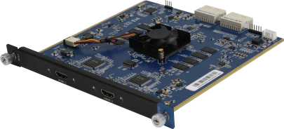
Output Module 4: Dual HDMI 2.0 Output Module

IllustrationKey Features
+ Fully modular architecture + Output resolution up to 3840×2160@60Hz + Up to 8 layers support for a single module and display Spanning does not consume layers + Support hot swap
ItemDescription
ConnectorsOutput2×HDMI-A
PerformanceResolutionSMPTE/VESA 4096×2160p@25/50/59.94/60; 3840×2160p@50/59.94/60; 3840×1080p@30/60; 2560×1600p@60; 2560×1440p@60; 2048×1152p@60; 2560×816p@60; 1920×1200p@60; 1920×1080p@23.98/24/25/29.97/30/50/59.94/60; 1680×1050p@60; 1600×1200p@60; 1440×900p@60; 1400×1050p@60; 1360×768p@60; 1280×1024p@60; 1280×800p@60; 1280×720p@50/59.94/60; 1024×768p@60; Customized resolution
Customized Resolutions1024×768@60; 1280×720@50/59.94/60; 1280×800@60; 1280×1024@60; 1360×768@60; 1400×1050@60; 1440×900@60; 1600×1200@60; 1680×1050@60; 1920×1080@23.98/24/25/29.97/30/50/59.94/60; 1920×1200@60; 2560×816@60; 2048×1152@60; 2560×1440@60; 2560×1600@60; 3840×1080@60; 3840×2160@50/59.94/60; 4096×2160@25/50/59.94/60
Note: Resolutions listed above have been tested already, for other Customized resolutions not mentioned, please refer to the actual use.
Max Width/Height+ Max width: 4096 ( 4096×2160p@60 ) + Max height: 2160 ( 4096×2160p@60 )
Power Consumption17.7W
Frame Rate≤240Hz
Total Pixel Capacity≥8.84M (Million)
Transmission Rate≤20Gbps
Transmission Cable Length≤100m
PhysicalWeight0.26kg
Dimension202mm×190.8mm×20mm
Order CodeProduct Code790-1002-38-1

Output Module 5: Quad HDBaseT Output Module

IllustrationKey Features
+ Fully modular architecture + Resolution up to 1920×1200@60Hz + Up to 8 layers support for a single module and display Spanning does not consume layers + Extend up to 100m + Support hot swap
ItemDescription
ConnectorsOutput4×RJ45
PerformanceResolutionSMPTE 2160p@30/60; 1080p@30/50/60; 720p@30/50/60
VESA 1920×1080@60; 1600×1200@60; 1280×1024@60; 1280×768@60; 1024×768@60; 800×600@60
Transmission Rate≤20Gbps
Transmission Cable Length≤100m
Power Consumption26.1W
PhysicalWeight0.30kg
Dimension202mm×190.8mm×20mm
Order CodeProduct Code790-1002-47-1

Output Module 6: Streaming Output Module

IllustrationKey Features
+ Fully modular architecture + Output resolution up to 3840×2160@60Hz + HDMI 2.0 preview + USB 3.0 recording + Streaming via LAN port + USB-C port for connecting USB audio devices + Support simultaneous streaming to 2 platforms via RTMP, RTMPS, NDI + Support hot swap
ItemDescription
ConnectorsOutput1×HDMI-A; 1×USB-A; 1×RJ45 Gigabit Network Port; 1×USB-C
PerformanceResolutionSMPTE 2160p@50/60; 1080p@23.98/24.97/50/59.94/60; 720p@50/60
VESA 3840×2160@60; 1920×1080@60; 1360×768@60; 1280×1024@60; 1280×768@60; 1280×720@50/60; 1024×768@60
VideoVideo Formats: HDCP 2.2
Video Latency: ≥1 frame
Record/StorageRecord Formats: MP4
Disk Formats: FAT32(≤32 GB); exFAT(64GB~2T)
Supported StandardsUSB 3.0
H.265: ITU-T H.265/ ISO/IEC 23008-2
Coding performanceSupport H.264; H.265; NDI 6
NDI codingNDI, HX, NDI, HX2, NDI, HX3, Full NDI (comming soon)
RTMP codingSupport streaming software
Speed modeCBR, VBR, FIXQP, AVBR, QPMAP
Maximum output speed125Mbps
Power Consumption26.8W
**Transmission ** Cable Length≤100m
PhysicalWeight0.28kg
Dimension202mm×190.8mm×20mm
Order CodeProduct Code790-1002-45-1

Output Module 7: Quad Input & Quad Output Analog Audio Module

IllustrationKey Features
+ Fully modular architecture + Support volume adjustment + Support 4 inputs and 4 outputs + Video and audio switch synchronously + Support audio setting of different banks + Support extra any digital and analog audio + Support hot swap
ItemDescription
ConnectorsInput4×3.5mm audio jack
Output4×3.5mm audio jack
PerformanceSound ChannelStereo, Double Channels
Transmission Rate≤20Gbps
**Transmission ** Cable Length≤100m
Power Consumption6.5W
PhysicalWeight0.30kg
Dimension202mm×190.8mm×20mm
Order CodeProduct Code790-1002-28-1

Output Module 8: Dual HDMI 1.3 Output Module with Dante

IllustrationKey Features
+ Fully modular architecture + Dante input and outputs with up to 32 audio channels supported + Output resolution up to 2048×1152@60Hz + Switching between Dante audio and HDMI 1.3 embedded audio + Audio volume adjustment + Lossless audio transmission with low latency + Support hot swap
ItemDescription
ConnectorsOutput2×HDMI-A; 2×RJ45
PerformanceResolutionSMPTE/VESA 2048×1152p@60; 2560×816p@60; 1920×1200p@60; 1920×1080p@23.98/24/25/29.97/30/50/59.94/60; 1680×1050p@60; 1600×1200p@60; 1440×900p@60; 1400×1050p@60; 1366×768p@60; 1360×768p@60; 1280×1024p@60; 1280×800p@60; 1280×720p@50/59.94/60; 1024×768p@60; Customized resolution
Customized Resolutions1536×960p@60; 1840×960p@60; 1920×1152p@60; 1920×1200p@60; 1872×1152p@60; 2048×1152p@60; 1536×1536p@60; 2048×1080p@60; 2304×1080p@60; 2560 × 960p@60; 3840×640p@60; 3840×1080p@30; 640×3840p@30/50; 512×3840p@50; 1152×1536p@60
Note: Resolutions listed above have been tested already, for other Customized resolutions not mentioned, please refer to the actual use.
Max Width/Height+ Max width: 3840 (3840×640p@60) + Max height: 3840 (640×3840p@50)
Power Consumption16W
Sampling Rate48KHZ
Frame Rate≤240Hz
Total Pixel Capacity≥2.45M (Million)
Transmission Rate≤20Gbps
**Transmission ** Cable Length≤100m
PhysicalWeight0.31kg
Dimension202mm×190.8mm×20mm
Order CodeProduct Code790-1002-43-1

Output Module 9: 16-Layer Quad HDMI 1.3 Output Module

IllustrationKey Features
+ Fully modular architecture + Output resolution up to 1920×1080@60Hz + 2U/4U: 8+8 layer output (the last 8 layers are one-to-one duplicates of the first 8) + 8U: a true 16-layer display, each capable of sourcing from any individual input signal + Display Spanning does not consume layers; full support for layer cropping, scaling, and roaming + Support hot swap
ItemDescription
ConnectorsOutput4×HDMI-A
PerformanceResolutionSMPTE/VESA 1920×1080p@23.98/24/25/29.97/30/50/59.94/60; 1680×1050p@60; 1600×1200p@60; 1440×900p@60; 1400×1050p@60; 1366×768p@60; 1360×768p@60; 1280×1024p@60; 1280×800p@60; 1280×720p@50/59.94/60; 1024×768p@60; Customized resolution
Customized Resolutions1536×960p@60; 1840×960p@60; 1920×1152p@60; 1920×1200p@60; 1872×1152p@60; 2048×1152p@60; 1536×1536p@60; 2048×1080p@60; 2304×1080p@60; 2560×960p@60; 3840×640p@60; 3840×1080p@30; 640×3840p@30/50; 512×3840p@50; 1152×1536p@60
Note: Resolutions listed above have been tested already, for other Customized resolutions not mentioned, please refer to the actual use.
Max Width/Height+ Max width: 3840 (3840×640p@60) + Max height: 3840 (640×3840p@50)
Power Consumption19W
Frame Rate≤240Hz
Total Pixel Capacity≥2.45M (Million)
Transmission Rate≤20Gbps
Transmission Cable Length≤100m
PhysicalWeight0.28kg
Dimension202mm×190.8mm×20mm
Order CodeProduct Code790-1002-50-0

Output Module 10: 16-Layer Quad DVI Output Module

IllustrationKey Features
+ Fully modular architecture + Output resolution up to 1920×1080@60Hz + 2U/4U: 8+8 layer output (the last 8 layers are one-to-one duplicates of the first 8) + 8U: a true 16-layer display, each capable of sourcing from any individual input signal + Display Spanning does not consume layers; full support for layer cropping, scaling, and roaming + Support hot swap
ItemDescription
ConnectorsOutput4×DVI-I
PerformanceResolutionSMPTE/VESA 1920×1080p@23.98/24/25/29.97/30/50/59.94/60; 1680×1050p@60; 1600×1200p@60; 1440×900p@60; 1400×1050p@60; 1366×768p@60; 1360×768p@60; 1280×1024p@60; 1280×800p@60; 1280×720p@50/59.94/60; 1024×768p@60; Customized resolution
Customized Resolutions1536×960p@60; 1840×960p@60; 1920×1152p@60; 1920×1200p@60; 1872×1152p@60; 2048×1152p@60; 1536×1536p@60; 2048×1080p@60; 2304×1080p@60; 2560 × 960p@60; 3840×640p@60; 3840×1080p@30; 640×3840p@30/50; 512×3840p@50; 1152×1536p@60
Note: Resolutions listed above have been tested already, for other Customized resolutions not mentioned, please refer to the actual use.
Max Width/Height+ Max width: 3840 (3840×640p@60) + Max height: 3840 (640×3840p@50)
Power Consumption21W
Frame Rate≤240Hz
Total Pixel Capacity≥2.45M (Million)
Transmission Rate≤20Gbps
Transmission Cable Length≤100m
PhysicalWeight0.28kg
Dimension202mm×190.8mm×20mm
Order CodeProduct Code790-1002-52-0

Output Module 11: 16-Layer Quad 3G SDI Output Module

IllustrationKey Features
+ Fully modular architecture + Output resolution up to 1920×1080@60Hz + 2U/4U: 8+8 layer output (the last 8 layers are one-to-one duplicates of the first 8) + 8U: a true 16-layer display, each capable of sourcing from any individual input signal + Display Spanning does not consume layers; full support for layer cropping, scaling, and roaming + Support hot swap
ItemDescription
ConnectorsOutput4×BNC
PerformanceResolutionSMPTE 1920×1080p@23.98/24/25/29.97/30/50/59.94/60; 1280×720p@50/59.94/60
Power Consumption19W
Frame Rate≤240Hz
Total Pixel Capacity≥2.07M (Million)
Transmission Rate≤20Gbps
Transmission Cable Length≤100m
PhysicalWeight0.34kg
Dimension202mm×190.8mm×20mm
Order CodeProduct Code790-1002-53-0

Output Module 12: 16-Layer Quad HDBaseT Output Module

IllustrationKey Features
+ Fully modular architecture + Resolution up to 1920×1080@60 + 2U/4U: 8+8 layer output (the last 8 layers are one-to-one duplicates of the first 8) + 8U: a true 16-layer display, each capable of sourcing from any individual input signal + Display Spanning does not consume layers; full support for layer cropping, scaling, and roaming + E×tend up to 100m + Support hot swap
ItemDescription
ConnectorsOutput4×RJ45
PerformanceResolutionSMPTE 2160p@30/60; 1080p@30/50/60; 720p@30/50/60
VESA 1920×1080@60; 1600×1200@60; 1280×1024@60; 1280×768@60; 1024×768@60; 800×600@60;
Transmission Rate≤20Gbps
Transmission Cable Length≤100m
PhysicalWeight0.30kg
Dimension202 mm×190.8 mm×20 mm
Order CodeProduct Code790-1002-51-0

Output Module 13: 8-CH HDMI 1.3 Output Module (dedicated for use with 8U, coming soon)

IllustrationKey Features
+ Output resolution up to 1920×1080@60Hz + Up to 16 layers support for a single module and display spanning does not consume layers
ItemDescription
ConnectorsOutput4×HDMI-A
PerformanceResolutionSMPTE/VESA 1920×1080p@23.98/24/25/29.97/30/50/59.94/60; 1680×1050p@60; 1600×1200p@60; 1440×900p@60; 1400×1050p@60; 1366×768p@60; 1360×768p@60; 1280×1024p@60; 1280×800p@60; 1280×720p@50/59.94/60; 1024×768p@60;
Max Width/Height+ Max width: 3840 (3840×640p@60) + Max height: 3840 (640×3840p@50)
Frame Rate≤240Hz
Total Pixel Capacity≥2.45M (Million)
Transmission Rate≤20Gbps
Transmission Cable Length≤100m
PhysicalWeight0.3kg
Dimension202mm×190.8mm×20mm
Order CodeProduct Code790-2002-51-0

7.3Communication Module

Communication Module: Communication Module with PVW

IllustrationKey Features
+ Fully modular architecture + Support hot swap
ItemDescription
ConnectorsTypeDescription
1×PVW (HDMI)Used for multi-window monitoring
1×IP (H.265)Used for remote control and IP echo
1×LANConnected to router or control PC to realize software control
1×RS232Connected to router or control PC to realize software control or device upgrade
1×USBUsed for device upgrade
1×TRSUsed for audio monitoring
1×IN-GENLOCK- LOOPConnected to a synchronization signal + IN: Used to accept the sync signal + LOOP: Used to loop the sync signal
PhysicalWeight0.30kg
Dimension202mm×190.8mm×20mm
Order CodeProduct Code790-1002-37-1

8Video Source Specification

Input

Input ModuleConnectorsBit DepthColor Space/SamplingInput Resolutions
Input Module 1HDMI 2.08bitRGB4: 4: 43840×2160@60
YCbCr4: 4: 4
YCbCr4: 2: 2
Input Module 2HDMI 1.38bitRGB4: 4: 41920×1080@60
YCbCr4: 4: 4
YCbCr4: 2: 2
10bit/12bitRGB4: 4: 4≥1280×720@60
YCbCr4: 4: 4
YCbCr4: 2: 2
Input Module 3DVI8bitRGB4: 4: 41920×1080@60
YCbCr4: 4: 4
YCbCr4: 2: 2
10bit/12bitRGB4: 4: 4≥1280×720@60
YCbCr4: 4: 4
YCbCr4: 2: 2
Input Module 4SDI10bitYCbCr4: 2: 21920×1080@60
📢  Notes

For requirements of other resolutions, frame rates and bit depths on input module, please contact RGBlink for customization.

Output

Output ModuleConnectorsBit DepthColor Space/SamplingOutput Resolutions
Output Module 1HDMI 1.38bitRGB4: 4: 41920×1080@60
YCbCr4: 4: 4
YCbCr4: 2: 2
10bit/12bitRGB4: 4: 4≥1280×720@60
YCbCr4: 4: 4
YCbCr4: 2: 2

9Order Codes

Product CodeItem
710-2016-02-1Q16pro Gen2 2U (Communication Module with PVW Included)
710-2016-04-1Q16pro Gen2 4U (Communication Module with PVW Included)
710-2016-08-1Q16pro Gen2 8U (Communication Module with PVW Included)
790-1002-10-1Q Series Quad HDMI 2.0 Input Module
790-1002-32-1Q Series Single IP Input Module
790-1002-33-1Q Series Single 4K60 Input Module
790-1002-34-1Q Series Quad 3G SDI (LOOP) Input Module
790-1002-35-1Q Series Quad DVI Input Module
790-1002-44-1Q Series Dual HDMI 1.3 & Dual DVI Input Module
790-1002-46-1Q Series Quad HDBaseT Input Module
790-2002-01-0Q Series 8-CH HDMI 1.3 Input Module (dedicated for use with 8U, coming soon)
790-2002-02-0Q Series Dual 4K60Hz Input Module (dedicated for use with 8U, coming soon)
790-1002-28-1Q Series Quad Input & Quad Output Analog Audio Module
790-1002-36-1Q Series Quad HDMI 1.3 Output Module
790-1002-38-1Q Series Dual HDMI 2.0 Output Module
790-1002-40-1Q Series Quad 3G SDI Output Module
790-1002-41-1Q Series Quad DVI Output Module
790-1002-45-1Q Series Streaming Output Module
790-1002-43-1Q Series Dual HDMI 1.3 Output Module with Dante
790-1002-47-1Q Series Quad HDBaseT Output Module
790-1002-50-0Q Series 16-Layer Quad HDMI 1.3 Output Module
790-1002-51-0Q Series 16-Layer Quad HDBaseT Output Module
790-1002-52-0Q Series 16-Layer Quad DVI Output Module
790-1002-53-0Q Series 16-Layer Quad 3G SDI Output Module
790-2002-51-08-CH HDMI 1.3 Output Modules (dedicated for use with 8U, coming soon)
790-1002-37-1Q Series Communication Module with PVW
950-0016-00-1Q Series 300W Redundant Power Module (for 2U)
950-1004-01-1Q Series 300W Redundant Power Module (for 4U)
950-0017-00-1Q Series 550W Redundant Power Module (for 8U)

10Revision History

VersionDateDescriptionAuthor
V2.82026-04-20Publish documentation online.ZYL
V2.72025-6-181. Add dual 4K60 input for 8UZFH
V2.62025-09-241. Add specifications of the 8-CH HDMI input and output modules. 2. Add power consumption of 2/4/8U and different I/O modules.FMY
V2.52025-09-041. Clarified the required chassis size and modules of the 16 layer roaming and 8+8 layer output. 2. Update the descriptions of the output modules to the latest firmware.FMY
V2.42025-08-25Correct the net weight of product models.FMY
V2.32025-06-23Change the order codes of the 2/4/8U models.FMY
V2.22025-03-26Delete Quad HDMI 1.3 Input Module and add Quad HDMI 2.0 Input Module.FMY
V2.12025-02-13Change some of the order codes.FMY
V2.02024-10-311. Add single card decoding capability (IP input module). 2. Add Streaming Output Module NDI coding.PCH
V1.92024-07-23Upgrade point: support 16 layersYJ
V1.82024-04-17Add single card decoding capability (IP input module)YJ
V1.72024-03-131. Add 8U model:front panel, rear panel. 2. Add specification: quad HDBaseT input module、quad HDBaseT output module .YJ
V1.62024-01-121. Add specification: dual HDMI 1.3 & dual DVI input module, dual HDMI 1.3 output module with Dante, streaming output module, quad input & quad output analog audio module. 2. Add dimension drawing: 8U model and module.YJ
V1.52023-12-19Add optional input and output modules.YJ
V1.42023-09-06Add frame rate & Total Pixel Capacity of HDMI 1.3、DVI、HDMI 2.0 input and output modules.YJ
V1.32023-08-171. Add 4U net & packaged weights, module weights, video source specifications. 2. Update dual HDMI 2.0 output module resolution.YJ
V1.22023-06-151. Add input&output module parameters. 2. Add notes and cautions.YJ
V1.12023-05-06Revise order codes.YJ
V1.02023-03-30First Release.YJ

11Q16pro Gen2 - This User Manual

Thank you for choosing RGBlink Q16pro Gen2.

This manual provides information on the device features, installation and operation. A glossary is provided at the end of this manual for reference.

Before using the device for the first time, please read this manual carefully to ensure safe and proper use of the product.

1About Your Product

Meet Q16pro Gen2

Q16pro Gen2 adopts a high-performance video image processing system with a pure hardware wire-speed processing architecture, which is suitable for education and scientific research, government announcements, information publishing, administrative management, military command, exhibitions, security monitoring, commercial sales and other industries.

The modular input and output card structure is adopted, and the arbitrary mixing function of the input card is realized at the same time. Not only can it easily access the common HDMI®/DVI/SDI/IP/AUDIO/DANTE/HDBASET and other multiple signals, but also support DP 1.2, HDMI 2.0 and other ultra-high resolution 4K/8K signal input and output, easily realize 4K multi-screen point-to-point splicing.

Key Features

  • Each module support 16 screens spanning the output port without occupying layers
  • 12 bit input and output, RGB 4:4:4 color space
  • Triple independent OSD rolling subtitles
  • Multi-window monitoring for inputs
  • i-signal output supported
  • LOGO overlay
  • Seamless switch between signals and scenes
  • Dual power module backup

1.1In the Box

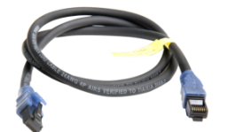
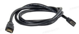
1×AC Power Cable1×Network Cable1×HDMI Cable1×Anti-static Bag

1.2Front Panel

ModelIllustrations
Q16pro Gen2 2U
Q16pro Gen2 4U
Q16pro Gen2 8U
NameDescription
LCD Touch Screen+ Display current status of the device. + For menu operation.
Power Button+ Press the button to power on or power off the device. + Button light turns red when powered on.
USB PortUsed for device upgrade.
HandlesFor carrying device.
Rack Mount EarsUse with the load-bearing screws to fix device on the rack.
PadSupport device and enhance shock absorption capability.

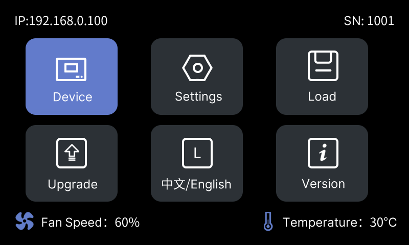
1.3Main Menu

After powered on, the LCD touch screen will show LOGO and then enter the main menu.

The Main Menu includes: Device, Settings, Load, Upgrade, Language and Version.

DeviceMain Menu
👉

1.3.1 Device

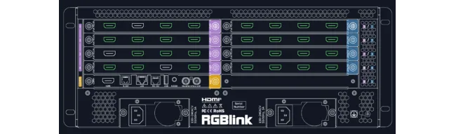
Click Device, the LCD screen will show the rear panel of Q16pro Gen2.

Document image

Indicator ColorStatus
GreenThere is a signal plug in
GreyNo signal for this port.

1.3.2 Settings

Click Settings to enter the page, which includes Communication Settings, Fan Control, Factory Reset.

Document image

Communication Settings

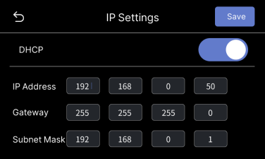
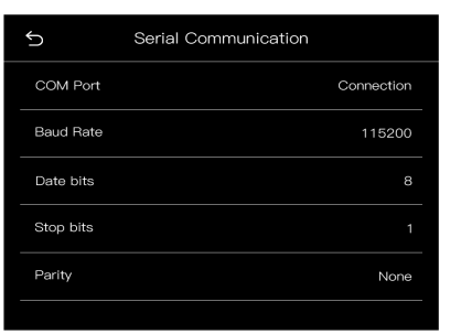
Click Communication Settings to do settings of IP and Serial Communication.

Document image

SettingsIllustrationDescription
IP SettingsDisplay IP address of the device by default. Disable DHCP to manually set the IP address, subnet mask and gateway. Click Save to save parameters.
Serial CommunicationCOM Port: default COM port. If connected, it will show Connection. + Baud Rate: 115200 (default) + Data Bits: 8 + Stop Bits: 1 + Parity: None
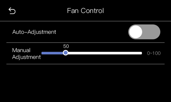
Fan Control

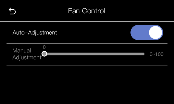
Click **Fan Control **to do settings of fan speed.

Two modes are optional. The default mode is Auto-Adjustment Mode. If you need to manually control the fan speed, please turn off the Auto-Adjustment Mode to adjust the fan speed.

Auto ModeManual Mode

If the temperature exceeds 70℃, a prompt will pop up on the LCD screen as shown above.

Document image

Factory Reset

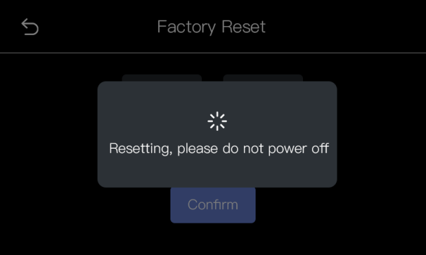
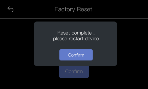
Click Factory Reset to enter the interface. In this interface, you can choose to Reset IP or Reset EDID. You can also choose to Reset both EDID and IP if necessary.

After clicking Confirm, the LCD screen will prompt "Resetting, please do not power off" during the process; After reset is completed, the screen will display "Reset completed, please restart device", as shown below:

ResettingReset Completed
👉

1.3.3 Load

📢  Notes

Please do Scene Setting in XPOSE firstly and then you can load bank. (Please refer to 3.3.6 Preset Management)

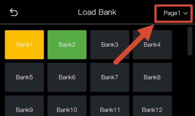
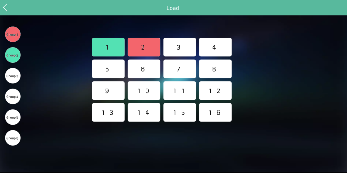
Click Load to enter the interface of load bank.

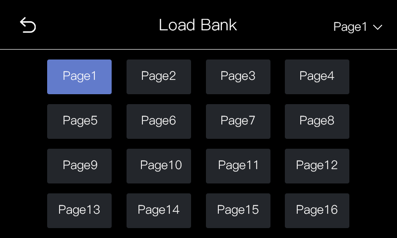
Bank: 16 banks in each page.Page: 16 pages optional
👉
Bank ColorDescription
Yellow backgroundcurrent bank
Green backgroundwith parameter saved
Grey backgroundempty bank

When the user selects the desired bank, the interface will pop up "Do you want to Load Bank X", shown as below. Click Confirm to do the selection.

Document image

1.3.4 Upgrade

Click Upgrade to enter the interface for device upgrade.

If no USB disk is inserted, the interface will prompt the user to insert the USB disk for upgrading.

Document image

If the user has inserted the USB disk, the interface will pop up a prompt for device upgrade. If the user selects "Confirm", the interface will start upgrading and show the progress bar.

ConfirmUpdrading
👉

After upgrade is completed, the interface will pop up a prompt to restart the device. Click [Confirm] to restart.

Document image

1.3.5 Language

Click 中文/English for language switching. Chinese and English are available.

Document image

1.3.6 Version

Click Version for overview of version info. The version of communication board, input boards and output boards will be shown in this interface.

Document image

1.4Rear Panel

ModelIllustrations
Q16pro Gen2 2U
Q16pro Gen2 4U
Q16pro Gen2 8UDocument image
NameDescription
Input Slots+ Support quad HDMI 1.3, quad DVI, quad 3G SDI (LOOP), dual HDMI 2.0 & dual DP 1.2, single IP, dual HDMI 1.3 & dual DVI,quad HDBaseT input module + Purple tip indicates input
Output Slots+ Support quad HDMI 1.3, quad 3G SDI, quad DVI, dual HDMI 2.0, dual HDMI 1.3 with Dante, quad HDBaseT, streaming output module, quad input & quad output analog audio module + Support input modules + Blue tip indicates output
Communication Slot+ Communication module with PVW - 1 × PVW (HDMI port) for multiwindow monitoring - 1 × IP (H.265 port) for remote control and IP echo - 1 × LAN for software control and device upgrade - 1 × RS232 serial port for software control - 1 × USB port for device upgrade - 1 × TRS audio jack for monitoring - 1 × INGENLOCKLOOP for connecting to a synchronization signal + Yellow tip indicates communication
Power SocketIEC power socket (1 standard & 1 backup)
Interface ProtectorUsed to pull out device, fix cables and protect interfaces from collision
Ground ScrewIncrease the safety and reliability, and avoid accidents such as fire and explosion caused by static electricity.

2Install Your Product


Q16pro Gen2 models share the same installation and connection procedure. 
Q16pro Gen2 4U is used as the example throughout this chapter.  

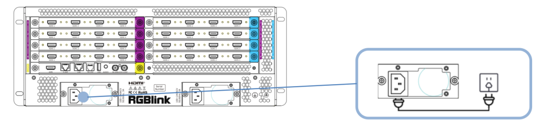
Connecting Power

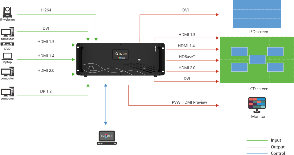
Connect Q16pro Gen2 4U to a power outlet using the standard AC power cord.

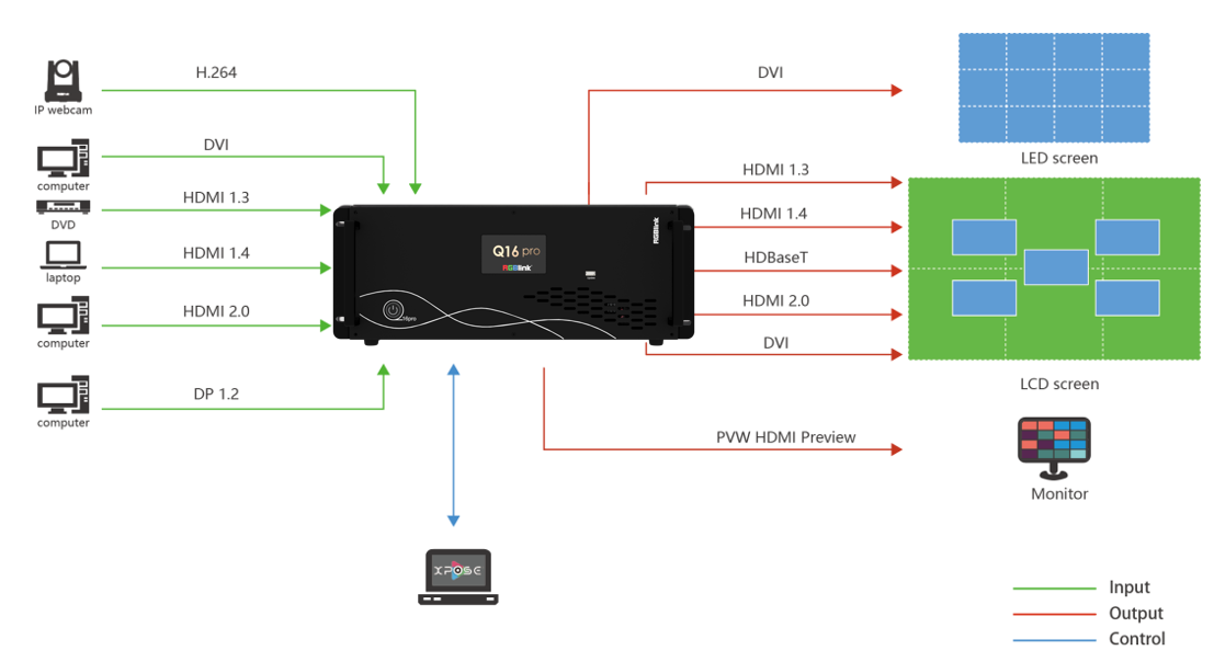
Connecting Signal Source and Control Computer

Q16pro Gen2 4U supports HDMI,SDI,DP 1.2,HDMI 2.0, HDBaseT and other optional input and output modules.

Q16pro Gen2 4U is operated by XPOSE, so it is necessary to connect device with control computer.

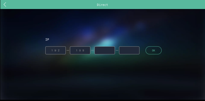
Method 1: Direct Connection: Do direct connection via communication connection or serial connection. It is suitable for single user to control the device.

Method 2: Router Connection: Connect control computer and Q16pro Gen2 4U with Router as shown in the figure above. It supports simultaneous online operation by multiple users.

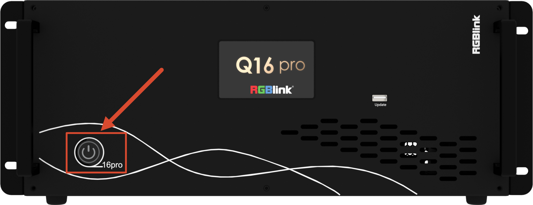
Powering On

After connection, slightly press the power button in the front panel to turn on Q16pro Gen2 4U.

3Use Your Product

Once installation and setup are complete, refer to this chapter for operating instructions.

The interfaces, images, and illustrations in this chapter are for reference only. Actual displays may vary by version. Please refer to the actual interface on your device.

3.1CPX

RGBlink CPX device supports controling Q16pro Gen2.

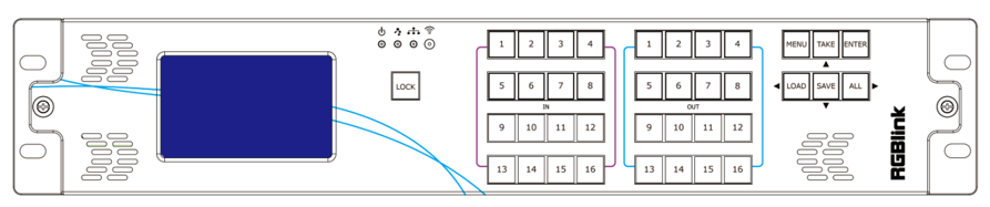
3.1.1Front Panel

Refer to the following table for the functions of the CPX buttons.

ButtonDescription
The LCD screen displays the menu interfaceduring menu operation.
Button lock: 1. Press and hold to lock or unlock the other buttons. The indicator lights up when the buttons are unlocked and turns off when they are locked. 2. The indicator is off by default.
Menu: 1. Press to open the Main Menu. 2. In a submenu, press to return to the previous menu.
Save/Up: 1. Press to save a preset in Scene Mode. 2. In the menu, use it as the Up key.
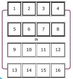
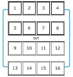
Switch Mode/Confirm: 1. Press to enter Switch Mode from Matrix Mode. In Switch Mode, select output ports with OUT 1-16, then select an input with IN 1-16 to route the input to the selected outputs. 2. Press again to return to Matrix Mode. 3. In the menu, press to confirm a selection.
Scene Mode/Left: 1. Press to enter Scene Mode from Matrix Mode. Press OUT 1-16 to load a saved scene. Only one scene can be selected at a time. 2. Press again to return to Matrix Mode. 3. In the menu, use it as the Left key.
OSD Mode/Down: 1. Press to enter OSD Mode from Matrix Mode. Press IN 1-16 to load OSD 1 or OUT 1-16 to load OSD 2 to the selected output port. 2. Press again to return to Matrix Mode. 3. In the menu, use it as the Down key.
Matrix Mode/Right: 1. CPX enters Matrix Mode automatically after startup. 2. In Matrix Mode, select an input with IN 1-16, then select one or more outputs with OUT 1-16 to route the input signal. 3. In the menu, use ALL as the Right key.
Input/Page/OSD 1: 1. In Matrix Mode and Switch Mode, select input ports 1-16. 2. In Scene Mode, select pages 1-16. 3. In OSD Mode, press IN 1-16 to load OSD 1 to the selected output port.
Output/Scene/OSD 2: 1. In Matrix Mode and Switch Mode, select output ports 1-16. 2. In Scene Mode, select scenes 1-16. In OSD Mode, press OUT 1-16 to load OSD 2 to the selected output port. 3. In the menu, use OUT 1-9 to enter numbers 1-9 and OUT 10 to enter 0.

3.1.2Rear Panel

PortDescription
DV 12V power socket
RS 232 port
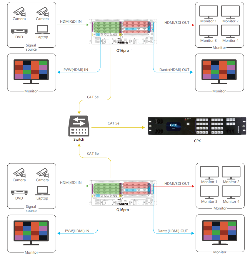
Connect two Q16pro devices to the same switch, and CPX can control two devices simultaneously.

3.1.3Connecting Devices

Q16pro Gen2 supports HDMI, SDI and other optional input and output modules.

Connect the devices

Connect the required input and output devices before configuring CPX.

  1. Connect the input source, such as a camera or computer, to the corresponding input port on Q16pro Gen2 with the appropriate cable.
  2. Connect the output device, such as a monitor, to the corresponding output port on Q16pro Gen2 with the appropriate cable.
  3. Connect Q16pro Gen2 to a power outlet using the standard AC power cord.
  4. Connect CPX to a power outlet using the standard 12V power adapter.
  5. Power on CPX and Q16pro Gen2.

Configure network communication

  • If the IP addresses of CPX and Q16pro Gen2 have not been modified, connect them directly with a network cable.
  • If the IP addresses are not in the same LAN, set the IP address of CPX to the same LAN as Q16pro Gen2. IP setting path: MENU > Search > Network Communications > Local IP
  • After CPX and Q16pro Gen2 establish network communication, "Connected" appears in the upper-left corner of the screen.

Select Q16pro Gen2

  1. Press the MENU button to open the menu.
  2. Select Search > Select Device.
  3. Select Q16pro Gen2.
 📢  Notes

Connect multiple devices to CPX through a switch to control multiple devices simultaneously.  

3.1.4Function Keys

CPX provides four operation modes for controlling Q16pro Gen2:

ButtonMode
Matrix Mode: Route input signals to output ports.
OSD Mode: Load OSD 1 or OSD 2 to output ports.
Switch Mode: Group output ports and switch the input signal assigned to the group.
Scene Mode: Load saved scenes.

3.1.4.1 Matrix Mode

CPX enters Matrix Mode automatically after startup.

The ALL key is enabled in Matrix Mode, as shown in the figure below.

In Matrix Mode, select an input signal from IN 1-16 and assign it to one or more output ports from OUT 1-16.

Check the input-output relationship on the LCD screen.

Route an input signal to an output port

For example, route input 1 to output 5 when input 1 is not assigned to any output port.

  1. Press IN 1. The IN 1 indicator lights up.
  2. Press OUT 5. The OUT 5 indicator lights up, and output 5 displays input 1.

Route an input signal to additional output ports

For example, input 1 is already assigned to output 5. Route input 1 to outputs 7 and 8.

  1. Press IN 1. The IN 1 and OUT 5 indicators light up to show the existing assignment.
  2. Press OUT 5 to remove input 1 from output 5. The OUT 5 indicator turns off.
  3. Press OUT 7 and OUT 8. The OUT 7 and OUT 8 indicators light up, and outputs 7 and 8 display input 1.

3.1.4.2 OSD Mode

Press SAVE to enter OSD Mode. The SAVE indicator lights up, as shown in the figure below.

In OSD Mode:

  • IN 1-16 loads OSD 1 to output ports 1-16.
  • OUT 1-16 loads OSD 2 to output ports 1-16.

CPX automatically detects the current OSD-to-output relationship after entering OSD Mode.

For example, if OSD 1 is loaded to output 3 and OSD 2 is loaded to output 5, the IN 3 and OUT 5 indicators light up, as shown in the figure below.

Load OSD 1 and OSD 2 to output ports

For example, load OSD 1 to output 10 and OSD 2 to output 12.

  1. Press IN 10. The IN 10 indicator lights up, indicating that OSD 1 is loaded to output 10.
  2. Press OUT 12. The OUT 12 indicator lights up, indicating that OSD 2 is loaded to output 12.

3.1.4.3 Switch Mode

Press ENTER to enter Switch Mode. The ENTER indicator lights up, as shown in the figure below.

In Switch Mode, selected output ports form a synchronous output group. Press an IN key to route an input signal to all output ports in the group.

When entering Switch Mode, CPX automatically detects the current synchronous output group.

For example, if outputs 1, 3, and 5 are in the synchronous output group, the OUT 1, OUT 3, and OUT 5 indicators light up, as shown in the figure below.

Configure a synchronous output group

For example, add outputs 9, 12, and 15 to the synchronous output group, remove output 1 from the group, and then route input 1 and input 5 to the group.

  1. Press OUT 9, OUT 12, and OUT 15 to add the outputs to the synchronous output group. The corresponding indicators light up.

  1. Press OUT 1 to remove output 1 from the group. The OUT 1 indicator turns off.
📢  Notes

Removing an output from the synchronous output group does not change its current input assignment. For example, if outputs 1, 3, and 5 display input 8 before output 1 is removed from the group, output 1 continues to display input 8.

  1. Press IN 1 to route input 1 to the synchronous output group. The IN 1 indicator lights up.

  1. Press IN 5 to route input 5 to the synchronous output group. The IN 5 indicator lights up.

3.1.4.4 Scene Mode

Press LOAD to enter Scene Mode. The LOAD indicator lights up, as shown in the figure below.

Press LOAD again to exit Scene Mode and return to Matrix Mode.

In Scene Mode, press OUT 1-16 to load the corresponding saved scene.

📢  Notes

Load only one scene at a time.

Load a scene when no scene is active

For example, load Scene 1 when no scene is currently active.

  1. Press LOAD to enter Scene Mode. The LOAD indicator lights up.
  2. Press OUT 1 to load Scene 1.
  3. Check the status on the LCD screen.

Switch to another scene

For example, Scene 5 is currently active. Switch to Scene 1.

  1. Press LOAD to enter Scene Mode. The LOAD indicator lights up.

  1. Press OUT 1 to load Scene 1.
  2. Check the status on the LCD screen.

Save a new scene

After setting the required input-output relationships, press TAKE to save the current configuration as a scene.

For example, save the current configuration to Scene 2.

  1. Press OUT 2 to select Scene 2.
  2. Press TAKE to save the current configuration to Scene 2.

3.1.5Main Menu

The Main Menu provides six options: Search, Mode, OSD, Language, Reset, and Admin.

3.1.5.1 Menu Navigation

In the Main Menu, use the following keys to navigate and confirm settings:

KeyFunction
TAKEUp
SAVEDown
LOADLeft
ALLRight
ENTERConfirm

Use Search to select the controlled device, configure network communication, and check device versions.

ItemDescription
Select DeviceSelect the device to control, such as Q16pro Gen2.
Network CommunicationsCheck or modify the IP addresses of CPX and the controlled device.
VersionCheck the version of CPX and the controlled device.

Network Communications

The Network Communications menu provides IP settings for CPX and the controlled device.

To modify an IP address:

  1. Select the IP address to modify.
  2. Press ENTER to enable editing. An asterisk (*) appears to indicate that the IP address is editable.
  3. Enter the IP address using OUT 1-16.

Device 1/2 IP menu provides the IP settings of the controlled device, such as Q16pro Gen2.

📢  Notes

Ensure that CPX and the controlled device are in the same LAN for network communication.

3.1.5.3 Mode

Use Mode to select the operation mode according to the required control method. The menu provides Matrix Mode, Switch Mode, and Scene Mode.

ItemDescription
Matrix ModeSelect an input from IN 1-16, then select one or more outputs from OUT 1-16 to route the input signal.
Switch ModeSelect multiple outputs from OUT 1-16 to form a synchronous output group, then select an input from IN 1-16 to route the input signal to the group.
Scene ModeLoad saved scenes using OUT 1-16.

3.1.5.4 OSD

Use OSD to check the OSD-to-output relationship.

Select an output port from 1-16 to check its OSD assignment.

3.1.5.5 Language

Use Language/语言 to switch the interface language.

  1. Press MENU to open the Main Menu.
  2. Select Language/语言.
  3. Select English or 简体中文.
  4. Press ENTER to confirm.
  5. The interface switches to the selected language.

3.1.5.6 Reset

🚨  Warning

Resetting the device restores all parameters to their default values, including IP address, EDID, and saved scenes.  

Use Reset to restore CPX or the controlled device to its default configuration.

  1. Press MENU to open the Main Menu.
  2. Select Reset.
  3. Select the required reset option.
  4. Press ENTER to confirm.
ItemDescription
Reset Local Machine and Target MachineRestore the default configuration of CPX and the controlled device.
Reset Local MachineRestore the default configuration of CPX only.

3.1.5.7 Admin

Use Admin to configure output resolution and communication preview mode.

Output Resolution

CPX provides two output resolution modes:

ItemDescription
Global ResolutionSet the same output resolution for all output ports on the selected module. Other modules can use different resolutions.
Independent ResolutionSet the output resolution independently for each output module.

Supported resolution:

1024×768@50, 1280×720@60, 1280×720@50, 1280×800@60, 1280×1024@60, 1360×768@60, 1366×768@60, 1400×1050@60, 1440×900@60, 1600×1200@60, 1680×1050@60, 1920×1080@60, 1920×1080@30, 1920×1080@50, 1920×1080@50i, 1920×1080@60i

Communication Preview Mode

ONLY Preview Input Mode is supported.

Select one of the following layouts: 4x4, 3x3, 2x2, 2+8, 2+4

3.2XPOSE 2.0


Current XPOSE 2.0 Version:2.0.8.17
For software download, please check rgblink official website > support page > proAV/proEvents > Software.

XPOSE 2.0 is a unified management and control platform for RGBlink devices. Users can configure input and output settings, manage display systems, manage layers and scenes, and configure system parameters through XPOSE 2.0.

The supported functions may vary depending on the device model. Refer to the corresponding documentation for details.

3.2.1XPOSE 2.0_Installation

System Requirements

Windows
ItemRequirement
Processor1 GHz or higher (32-bit or 64-bit)
CPUIntel® Core™ i5 or above
Memory4 GB or above
GraphicsDirectX 9 compatible, 128 MB VRAM or above (Aero enabled)
Storage16 GB or more available space (system partition, NTFS)
Operating SystemWindows 7 or later (Full version only; Ghost and customized editions are not supported)
macOS
ItemRequirement
CPUIntel® Core™ i5 or above
Display Resolution1680 × 1050 or higher
📢  Notes

If the display resolution is lower than 1680 × 1050, some features or interface elements may not be displayed correctly.  

Installation

Launch the Installer

Double-click the installer on the desktop.

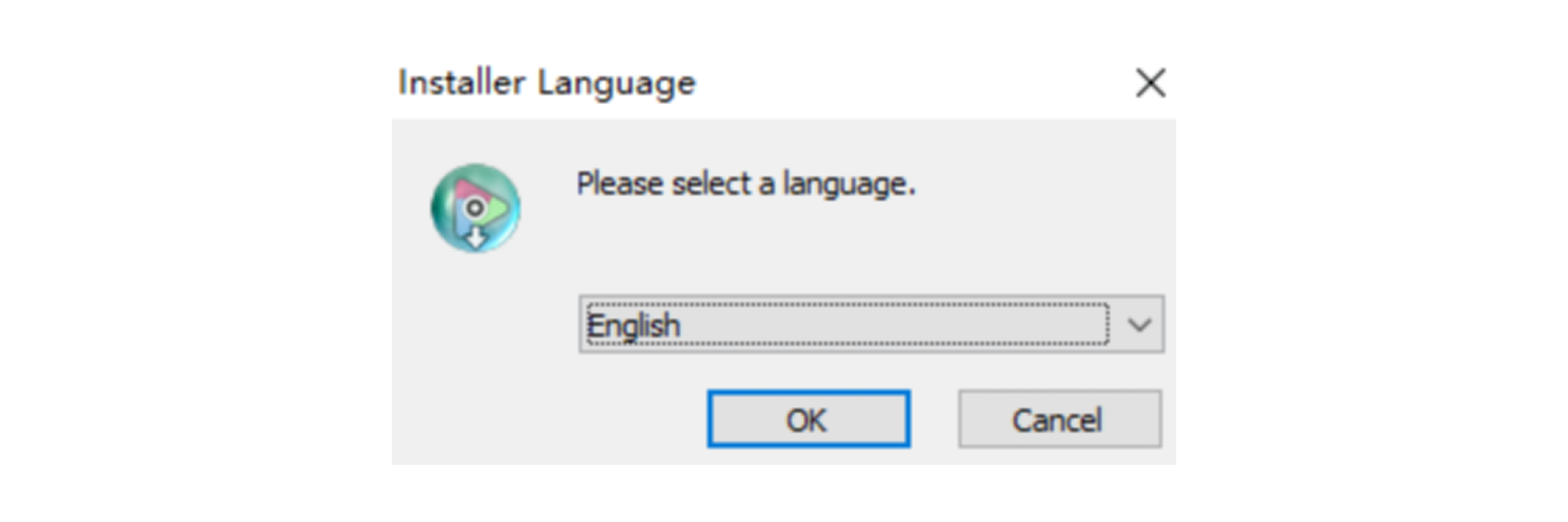
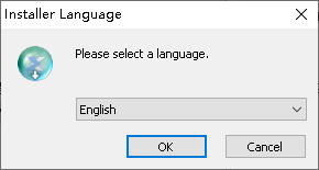
When the language selection dialog appears, choose the desired language and click OK.

Start Installation

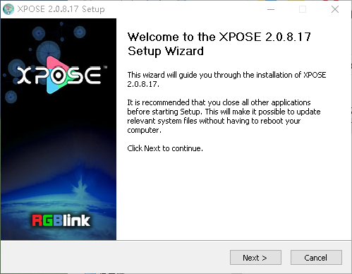
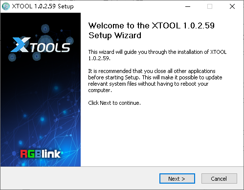
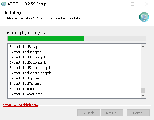
When the Setup Wizard opens, click Next> to continue.

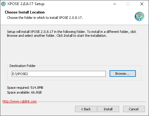
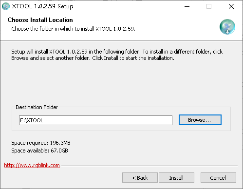
Select the Installation Location

Click Browse... to choose the installation directory, then click Install.

📢  Important

On Windows 7 or later, administrator privileges are required when installing to the system drive (C:).

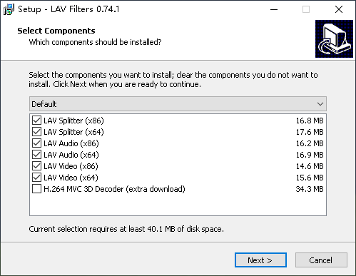
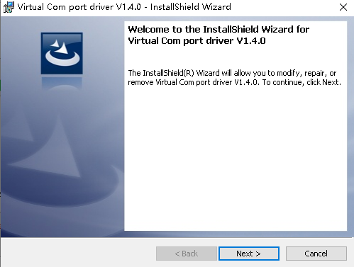
Install the Multimedia Components

During installation, the multimedia component installer opens automatically.

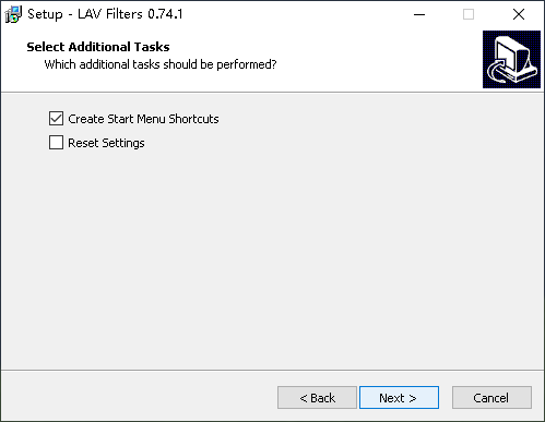
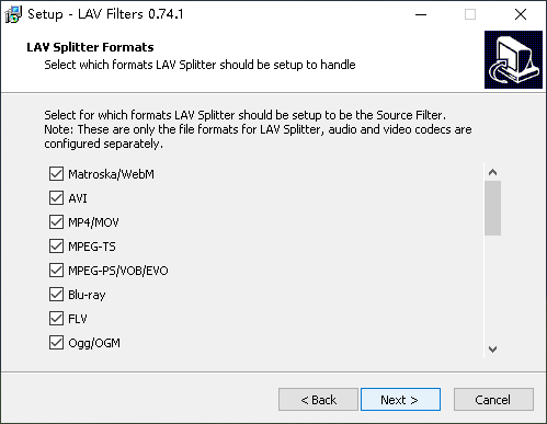
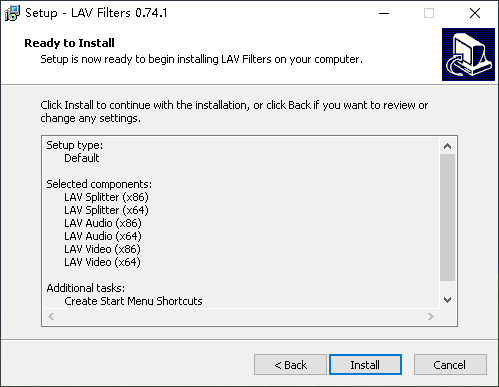
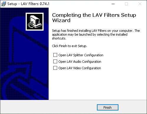
  • In Select Components, choose the required decoder components, then click Next >.

  • In Select Additional Tasks, configure the additional options, then click Next>.

  • In LAV Splitter Formats, select the required formats, then click Next >.

  • Review the installation settings, then click Install.

  • When installation is complete, click Finish.

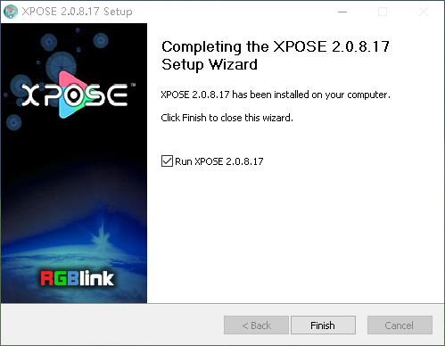
Complete the Installation

After the multimedia components are installed, the XPOSE Setup Wizard resumes.

Click Finish to complete the installation.

3.2.2XPOSE 2.0_Operation


Q16pro Gen2 models share the same XPOSE 2.0 workflow.
Q16pro Gen2 4U is used as the example throughout this chapter. 

Launching XPOSE

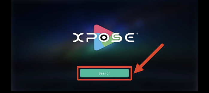
After installation, double-click the XPOSE 2.0 icon to launch the software.

When launching XPOSE for the first time, select the desired language and the local IP address, then click Start.
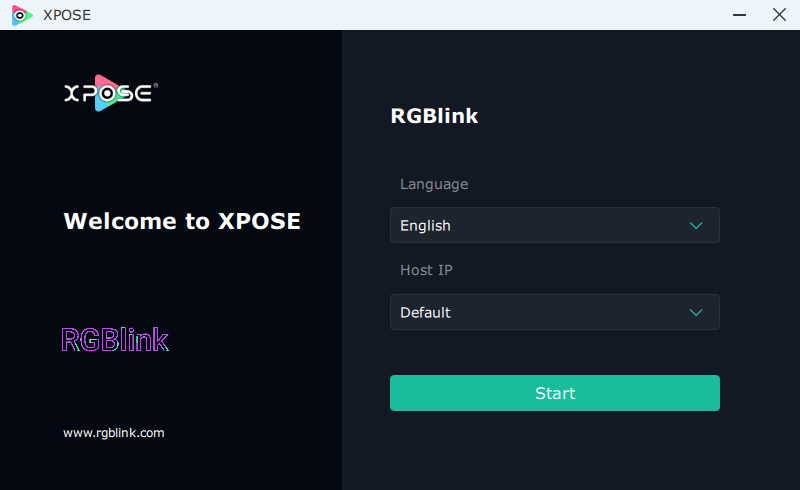
If a device is connected successfully, the main workspace displays the rear panel of the device.
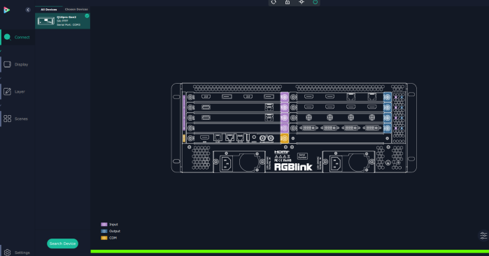
Workspace Overview

The XPOSE 2.0 workspace includes the following functional areas:

  • Workspace
  • System Settings
  • Properties
  • Device Connection
  • Input/Output Configuration
  • Display Management
  • Layer Configuration
  • Scene Management

The toolbar at the top of the workspace provides quick access to the following functions:

  • Synchronize Device
  • Lock Workspace
  • Center Rear Panel
  • Power On/Off

Use the mouse wheel to zoom in or out of the workspace.

Toolbar at the Top

System Settings

Click the ⚙ Settings icon in the lower-left corner to open the System Settings page.
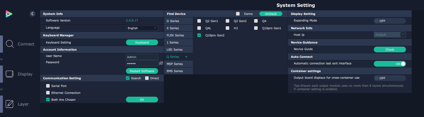
System Settings Page

The following settings are available.

System Info

Displays the current software version and language.

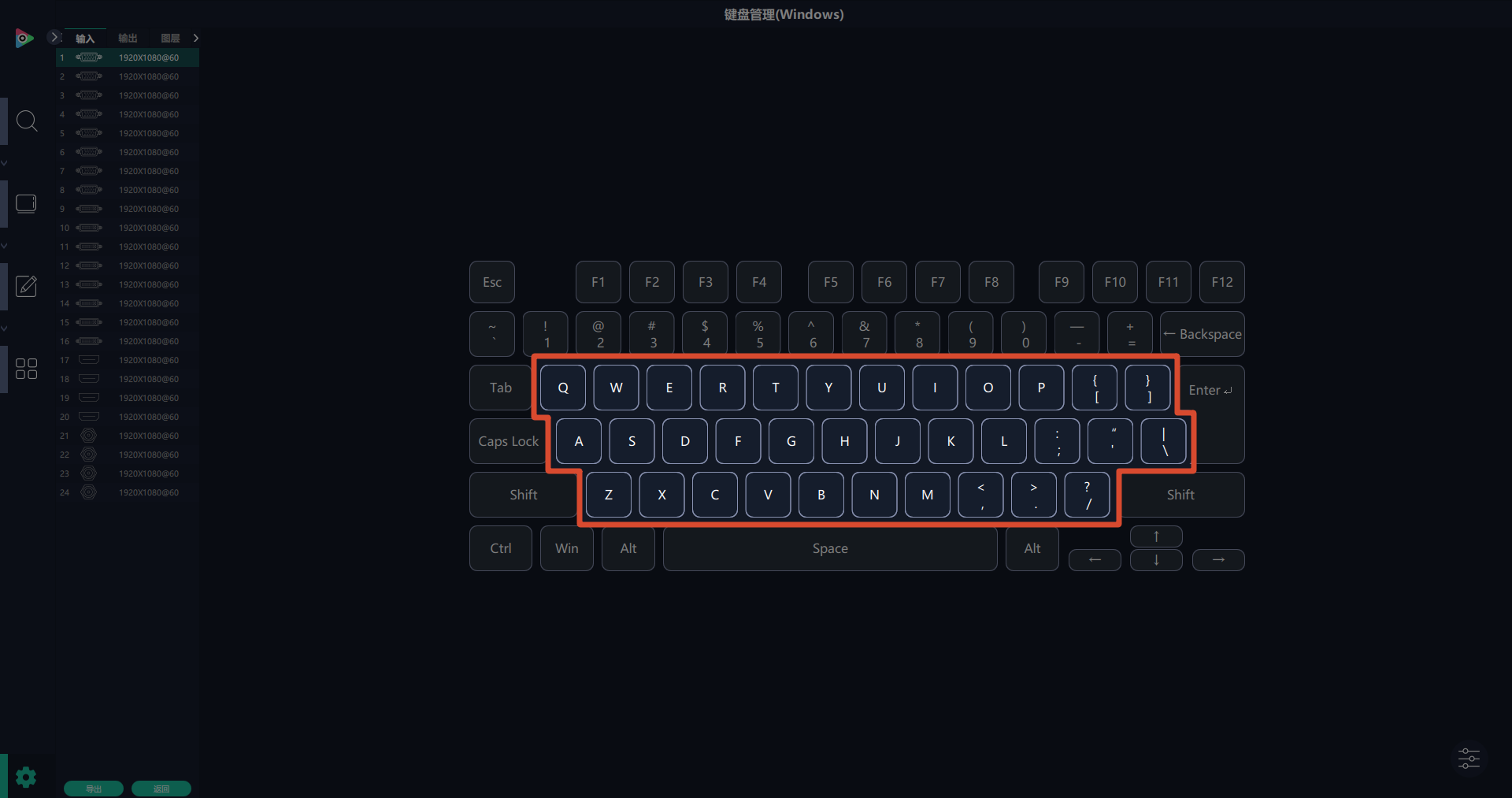
Keyboard Manager

Configure keyboard shortcuts for inputs, outputs, layers, and scenes.

Drag frequently used functions onto the corresponding keys. Shortcut configurations can also be exported or imported.
Account Information

Displays the current username and password.

You can also restart XPOSE from this page.

Communication Settings

Select the communication method used to connect the device.

Supported options include:

  • Serial Port
  • Ethernet Connection
  • Both are Chosen

Click OK to apply the changes.

Find Device

Select the product series and device model used for device discovery.

Display Settings

Configure the extended display mode.

Network Info

Displays the Host IP address.

Novice Guidance

Checks the XPOSE operation guide.

Auto Connect

When enabled, XPOSE automatically restores the previous workspace the next time the software starts.

Container Settings

Allows displays connected to the same output card to be shared across different containers.

User Management

Properties

Click the properties icon in the lower-right corner (as shown in the red circle) of the main workspace to open the device properties.

The properties page provides access to device Overview, IP, Fan Control, Backup, and Factory Setting and so on.

Overview
ItemIllustrationDescription
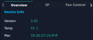
Device InfoThe Device Info page displays the communication board version, device temperature, and MAC address.
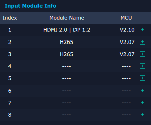
Input Module InfoThe Input Module Info page displays the installed input module name and MCU version. If no input module is installed, .... is displayed.
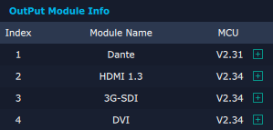
Output Module InfoThe Output Module Info page displays the installed output module name and MCU version.
IP

The IP page supports automatic and manual IP configuration.

In automatic mode, the device obtains the IP Address, Netmask, and Gateway automatically.

In manual mode, enter these parameters manually.

Fan Control

The Fan Control page supports automatic and manual fan speed control.

Set Fan Speed to 0-100 in manual mode.

📢  Notes

Set the manual fan speed to 30 or higher to ensure sufficient heat dissipation.  

Backup

The Backup page provides input and preset backup modes.

Set Backup to ON or OFF to enable or disable the backup function.

Set Backup Mode to Input Backup or Preset Backup. Click Add to add a backup source.

Factory Setting

The Factory Setting page provides options for clearing EDID parameters and retaining network settings after a reset.

  • Remove EDID: Clear the saved EDID parameters.
  • Save IP: Retain the current IP address after resetting the device.

Permission Management

On the System Settings page, click the properties icon to open Authorization.

**Authorization **allows you to create and edit user accounts, passwords, and operation permissions.

To modify user accounts, first enable Status.

Administrator Login

The first time you perform operations such as firmware upgrade or factory reset, XPOSE requires administrator authentication.

The default administrator account is:

  • Username: Admin
  • Password: admin
User Login

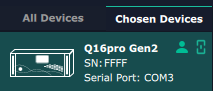
If user accounts have already been created, click the user icon under Main Workspace > **Connect **> Chosen Devices.

Enter the username and password, then click Log in.

The user icon turns green after a successful login.

Adding a User

Click New, enter the username and password, then click Save to create the account.

Device Connection
📢 Important

Before searching for devices, select the correct device model and communication method under System Settings > Find Device and Communication Setting.

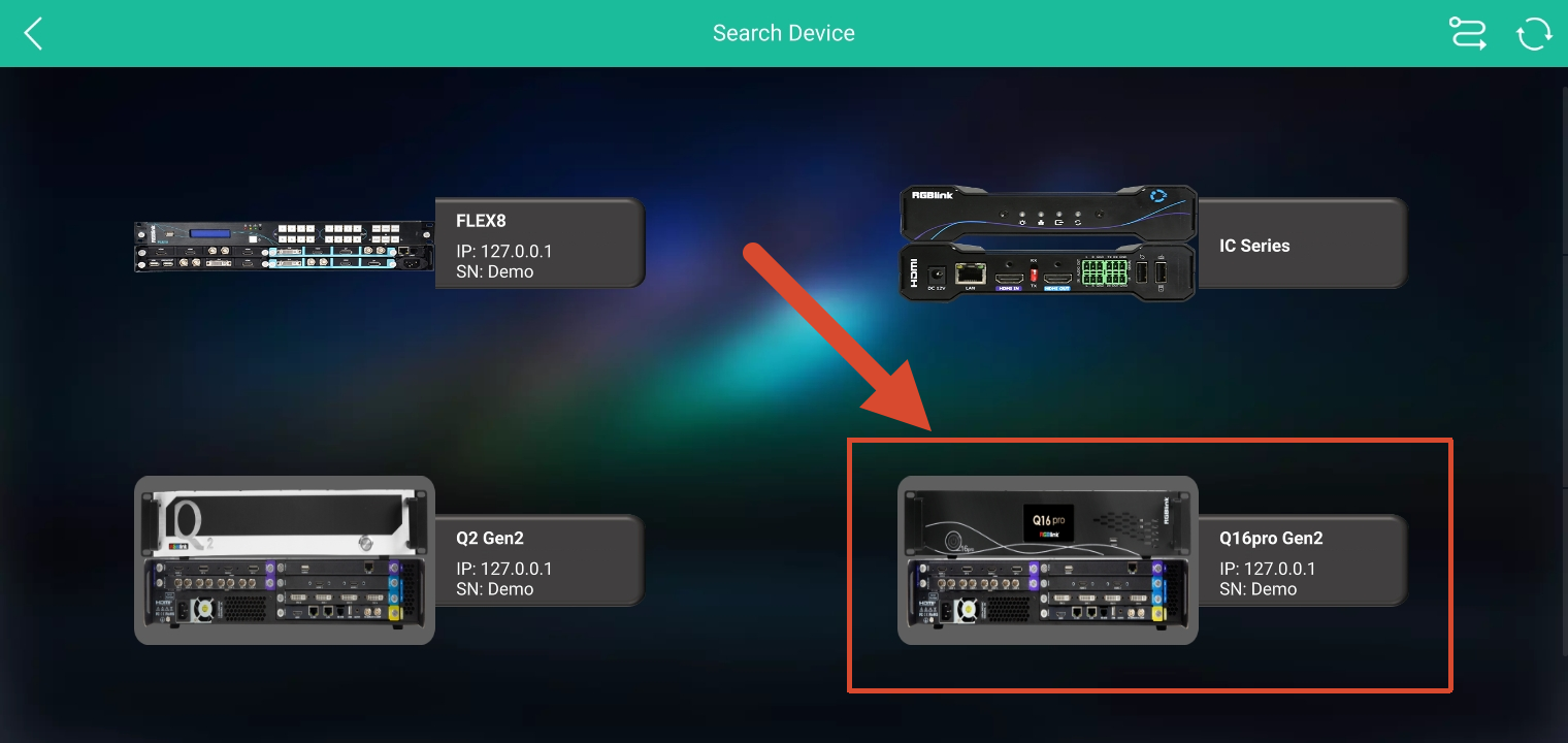
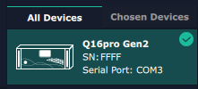
Click Connect > Search Device.

XPOSE searches for available devices through the selected communication interface.

After the search is complete:

  1. Select the target device from All Devices.
  2. Move it to Chosen Devices.

The device is now ready for configuration.
👉

Input and Output Configuration

Input and Output Configuration

The rear panel of Q16pro Gen2 is displayed in the workspace. Each input and output port can be configured independently.

Interface colors indicate signal status:

Interface ColorDescription
Red animated borderSelected signal
GreenNormal signal
YellowAbnormal signal
WhiteNo signal
📢  Notes

Due to hardware limitations, the SDI output interface always appears white regardless of its signal status.  
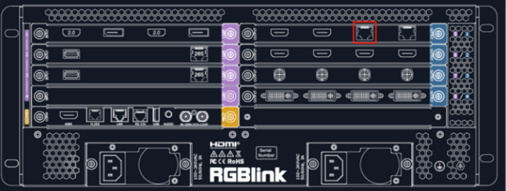
Highlighted Port

Port ColorIconDescription
PurpleInput port
BlueOutput port
YellowCommunication port
Input Configuration

Click an input port to select the board that contains the port. Configure the selected input port in the settings panel.

The selected port is highlighted with a red animated border.

Set EDID for the input port. The 4K settings appear when a 4K input module is installed.

EDID

Input Port: Displays the selected input port.

Basic Parameters

  • Monitor Name: Enter the monitor name.
  • Width / Height / Frequency: Enter custom parameters as required.

The following Q16pro Gen2 input modules support EDID:

  • Quad HDMI 2.0 Input Module.
  • Dual HDMI 2.0 & Dual DP 1.2 Input Module.
  • Quad DVI Input Module.
  • Dual HDMI 1.3 & Dual DVI Input Module.

For order codes, see Q16pro Gen2 - This Specification.

4K

Input Module: Displays the position of the selected port.

Basic Parameters >** Input Source:** Select an input port on the 4K input module.

Communication Board with PVW

When a Communication Board with PVW input module is installed on Q16pro Gen2, click an HDMI port to configure the following settings.

📢  Notes

4K signals are synchronized in PGM but may not be synchronized in PVW.  

ItemIllustrationDescription
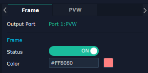
FrameStatus: Turn on status to set the frame color. Color: Set the frame color.
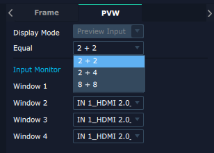
PVWDisplay Mode:Preview Input ONLY. Equal: Select 2+2 / 2+4 / 2+8 layout. Input Monitor: Select the input signal for each window.
Output Configuration

Select the output port to configure, then click the properties icon.

Output Resolution

The Resolution page configures the output resolution, Genlock, brightness, and output protocol.

ItemIllustrationDescription
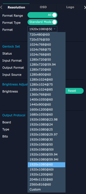
ResolutionSDI and HDMI output modules support output resolution settings. Format Range + ALL: Set the same output resolution for all output modules. + MODULE: Set the same output resolution for all output ports on the selected module. Other modules can use different resolutions. Format Type + Standard Mode + Customize. Enter Width, Height, and Refresh Rate, then click Set.
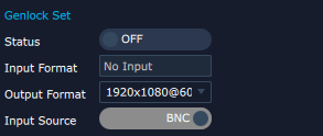
Genlock SetStatus: Turn the Genlock function on or off. Input Format: Displays the current input format. Output Format: Displays the current output format. Input Source: Switch to HDMI or BNC.
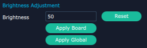
Brightness AdjustmentBrightness: Set the brightness from 0-100. The default value is 50. Apply Board: Apply the brightness setting to all output ports on the selected module. Apply Global: Apply the brightness setting to all output modules.
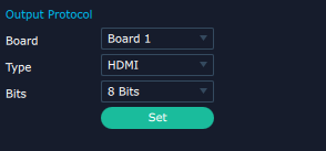
Output ProtocolBoard: Select Current Board or All Board. Type: Select DVI or HDMI. Bits: The bit depth is fixed at 8 bits for DVI. Select 8 bits, 10 bits, or 12 bits for HDMI.
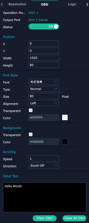
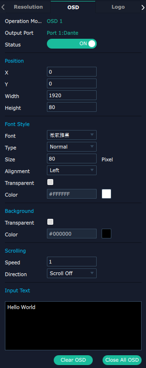
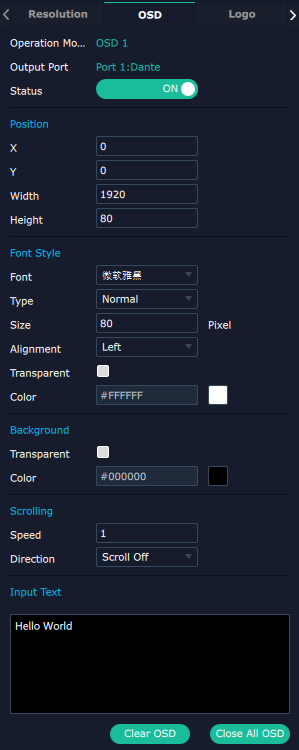
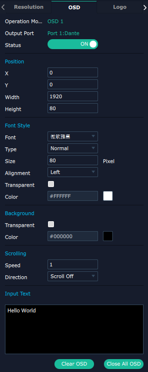
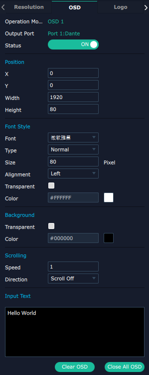
OSD

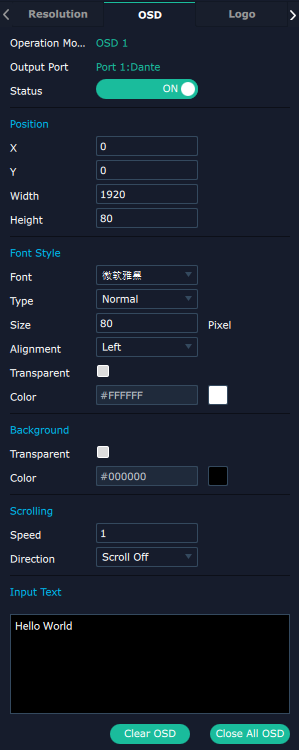
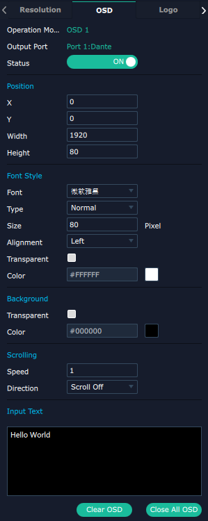
The OSD function overlays text on the output video. Turn Status on before configuring OSD parameters.

The following Q16pro Gen2 output modules support OSD:

  • Quad HDMI 1.3 Output Module.
  • Quad 3G SDI Output Module.
  • Quad DVI Output Module.
  • Dual HDMI 2.0 Output Module.
  • Dual HDMI 1.3 Output Module with Dante (preliminary).

For order codes, see Q16pro Gen2 - This Specification.

ItemIllustrationDescription
OSDOutput Port: Displays the selected output port. Status: Turn OSD on or off.
PositionX/Y: Set the horizontal and vertical starting position of the text. Width/Height: Set the horizontal and vertical size of the text.
Font StyleFont: Select a font installed on the computer. Font Type: Select Normal, Italic, Bold, or Bold Italic. Font Size: Set the font size from 0-300 pixels. Alignment: Set the text alignment.
BackgroundSelect a transparent background or set a background color.
ScrollingScroll Speed: Set the scroll speed from 0-16. Scroll Direction: Select Scroll Off or Scroll Left.
Input TextEnter the text to display.
Clear OSD/Close All OSDCustomize the OSD content, select Clear OSD to clear the current OSD, or select Close All OSD to disable all OSD.
📢  Notes

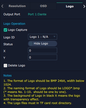
Store the logo on an SD card before capturing it. 

ItemIllustrationDescription
Output PortDisplays the selected output port.
Logo OperationLogo Capture: Select or cancel. Logo ID: Select a saved logo by its ID. Status: Show or hide. X/Y: Set the horizontal and vertical position Delete Logo: Delete the configured logo.
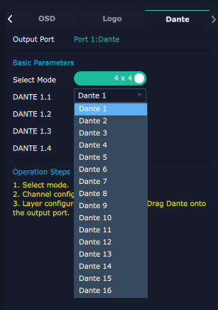
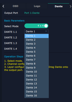
Dante

Q16pro Gen2 supports the Quad Input & Quad Output Analog Audio Module. Install this module in a slot that supports both input and output modules.

Configure additional audio settings on the Layer Configuration > Dante section.

ItemIllustrationDescription
Output PortDisplays the selected output port.
Basic ParametersSelect Mode: Select 4×4 or 16×16. DANTE 1.1 - DANTE 1.4: Configure the audio channels. Click Set to apply the settings.

Display Management

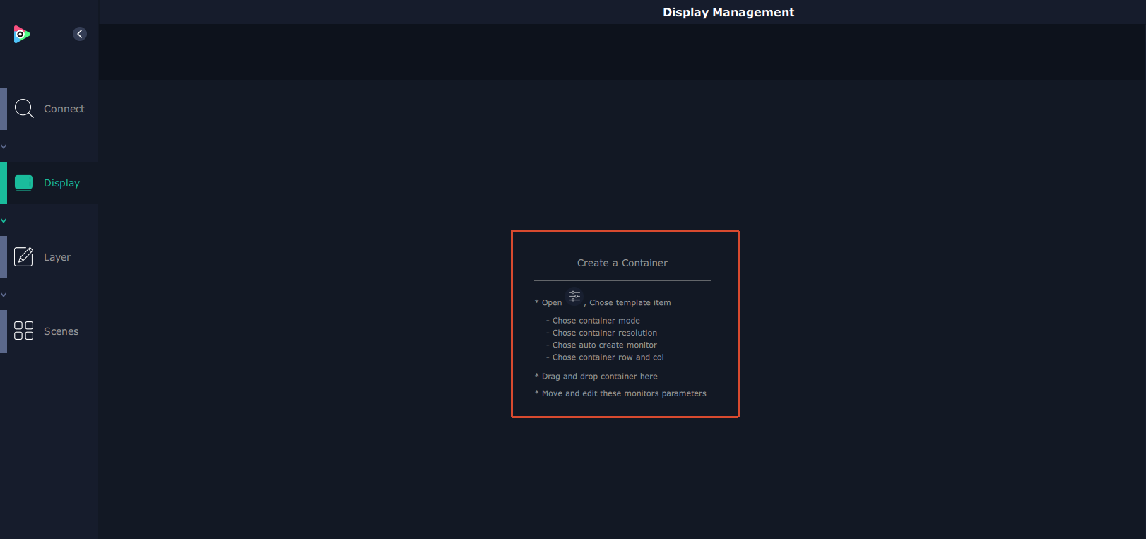
Display Management is used to create Containers and configure display layouts.

Click Display to open the Display Management page.

Q16pro Gen2 uses the Cross layout by default. To use a different layout, press and hold × in the upper-right corner of the current Container to delete it, then create a new Container.

Creating a Container

A Container defines the layout of the output displays. In XPOSE 2.0, a Container represents a complete display system, such as an LED display or an LCD video wall.

Click the properties icon, then configure the following:

  • Chose container mode
  • Chose container resolution
  • Chose auto create monitor
  • Chose container row and col

After the configuration is complete, drag the selected Container template into the workspace.
Operation Guidance

Configuring Displays

After creating a Container, you can adjust the display layout and position.

Click the properties icon to configure the Template, Output, and Display System.

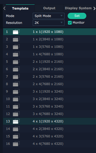
Template

XPOSE 2.0 supports multiple display modes simultaneously. Each Container is identified by a different border color.

To create a Container, drag a template to the workspace.

ItemIllustrationDescription
ModeSelect a display mode. Each mode uses a different color. Matrix Mode (default): Retains the Container when you change the resolution. Split Mode: Deletes the Container when you change the resolution. Create a new Container after changing the resolution.
ResolutionSelect the output resolution.
TemplateThe Template panel provides 16 basic display area layouts for creating Containers.
Custom Template

Select Template > Customize to create a custom Container.

Set Monitor Layout to Auto or Manual.

Create a Container as follows:

  1. Enter H Total, V Total, Row, and Column. XPOSE 2.0 automatically calculates H Item and V Item.
  2. Click Create. The Container appears in the workspace and displays the width and height of each display.
  3. Click Save to save the Container.

Adjusting the Container Layout

The following operations are supported:

  • Move: Drag the Container border to reposition it within the workspace.
  • Zoom: Click - or +, or use the mouse wheel while the pointer is inside the Container.
  • Delete: Press and hold × in the upper-right corner of the Container.
Output

The Output panel lists all output ports.

  • Active ports are available.
  • Gray ports are unavailable or already assigned.

To assign an output, drag the desired output port onto a display in the Container.

To replace an assigned output, drag another output port onto the target display. The original output becomes available again.

Display System

The Display System panel lists all created Containers.

Click the Edit icon (🖋) to rename a Container.

Layer Configuration

The Layer Configuration page manages layers assigned to each output.

Click Layer to open the Layer Configuration page.

The left panel displays the available Display Area, Dante, IPC, Layer, and Signal.

Display Area

The Display Area panel lists all Containers created in Display System.

Select a Container to display it in the workspace.

Dante

The number of Dante signals depends on the selected mode in Output Settings: four in 4 × 4 mode, and 16 in 16 × 16 mode.

  • Select a bank.
  • Drag an audio input from Signal List to the Container.
  • Drag another audio input to replace the current input.

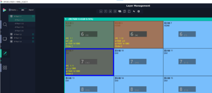
IPC

IPC stands for IP Camera.

This page displays IP camera signals received through the IP input module.
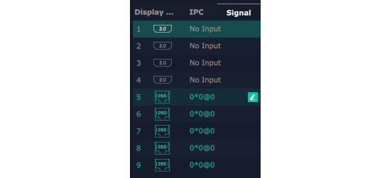
Signal

Displays all available input signals.

Drag a signal from the list onto the desired display within a Container.

By default, each signal is identified by its input resolution.

To rename a signal, click the Edit icon (🖋), enter a new name, then click √.
📢  Important

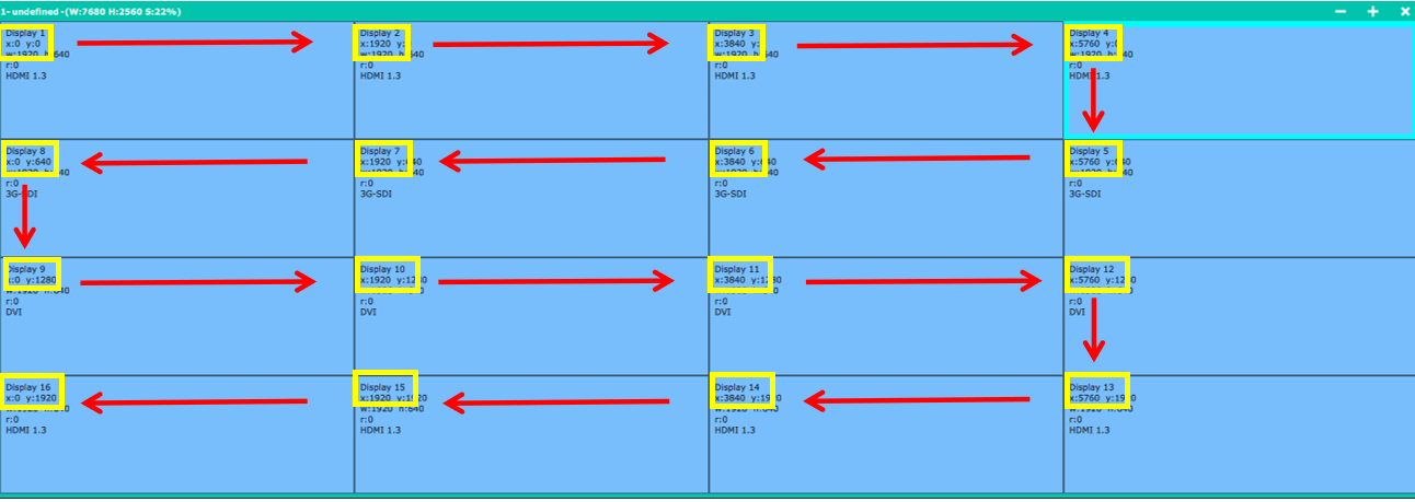
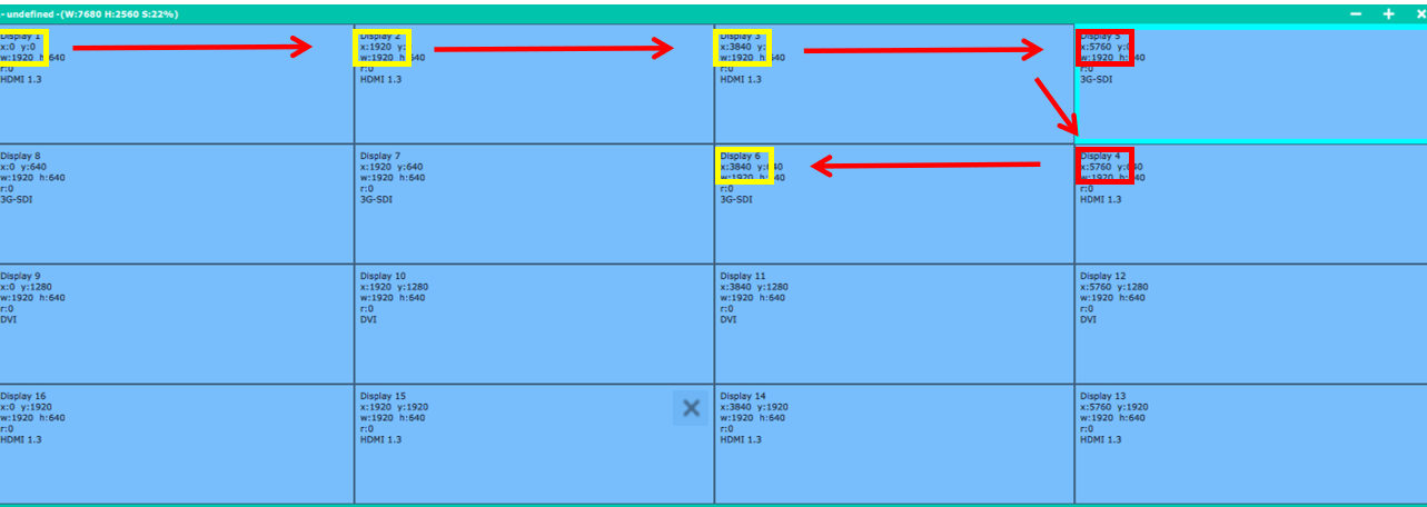
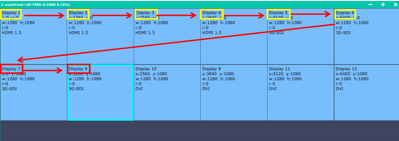
XPOSE uses an S-shaped connection order by default.

Connect the displays to the output ports in the same order to ensure correct image mapping. Each output port connects to one display.  

StatusIllustration
Correct
Incorrect: Display 1, 2, 3 and Display 4 are separated
Incorrect: Display 5, 6 and Display 7, 8 are separated
Layers

After a signal is assigned to a display, the Layers panel lists the corresponding layer number and signal.

The toolbar provides the following operations:

  • Bring to Front
  • Move Forward
  • Move Backward
  • Select All
  • Copy
  • Paste
  • Delete
📢  Notes

One signal occupies one layer. A 4K signal occupies four layers. Users can drag the same signal into a Container multiple times.  

Toolbar

Available Layers

The number displayed on each output indicates the remaining available layers.

As signals are added, the available layer count decreases. When no layers remain, additional signals cannot be assigned.

Layer number: 16 layers in total can be places on each output port. The number in the red rectangle on the right figure represents the number of layers that can be placed at the output.

Editing Layers

Select a layer, then click the properties icon.

Scaling and Cropping

Layers can be adjusted using either of the following methods.

Method 1

Select the layer and enter the X Position, Y Position, Width, and Height at the bottom of the workspace.

Click Save to apply the changes.

Method 2

Open the properties icon > Scale, then enter the X Position, Y Position, Width, and Height.

Click the Lock Aspect Ratio icon to maintain the aspect ratio when resizing.

Quick

Quick page provides a fast way to set the layer layout.

Drag and drop a source from Signal List onto the workspace. Click Set to apply the layout.

IllustrationDescription
Single Monitor: Select the Output Port to configure. Single Board: Select the Output Board to configure. All Monitors: Turn all monitors on or off. Layer Set: Set the layer layout.
Layer Setting Preview
Streaming

The H.265 Module supports image preview.

Image Quality supports smooth (default), normal, or HI-Q.

Enable preview as follows:

IllustrationStep
1. Turn on Layer Preview, Input Preview, Scene Preview, or Expand Preview as required.
2. Turn on H.265 to preview the image.
📢  Notes

H.265 is the master switch.  If H.264 is enabled first, H.265 can not be enabled successfully.  

Scene Management

Click Scenes to open the Scene Management page.

Click the button in the lower-left corner to switch between Manual Mode and Schedule Mode.
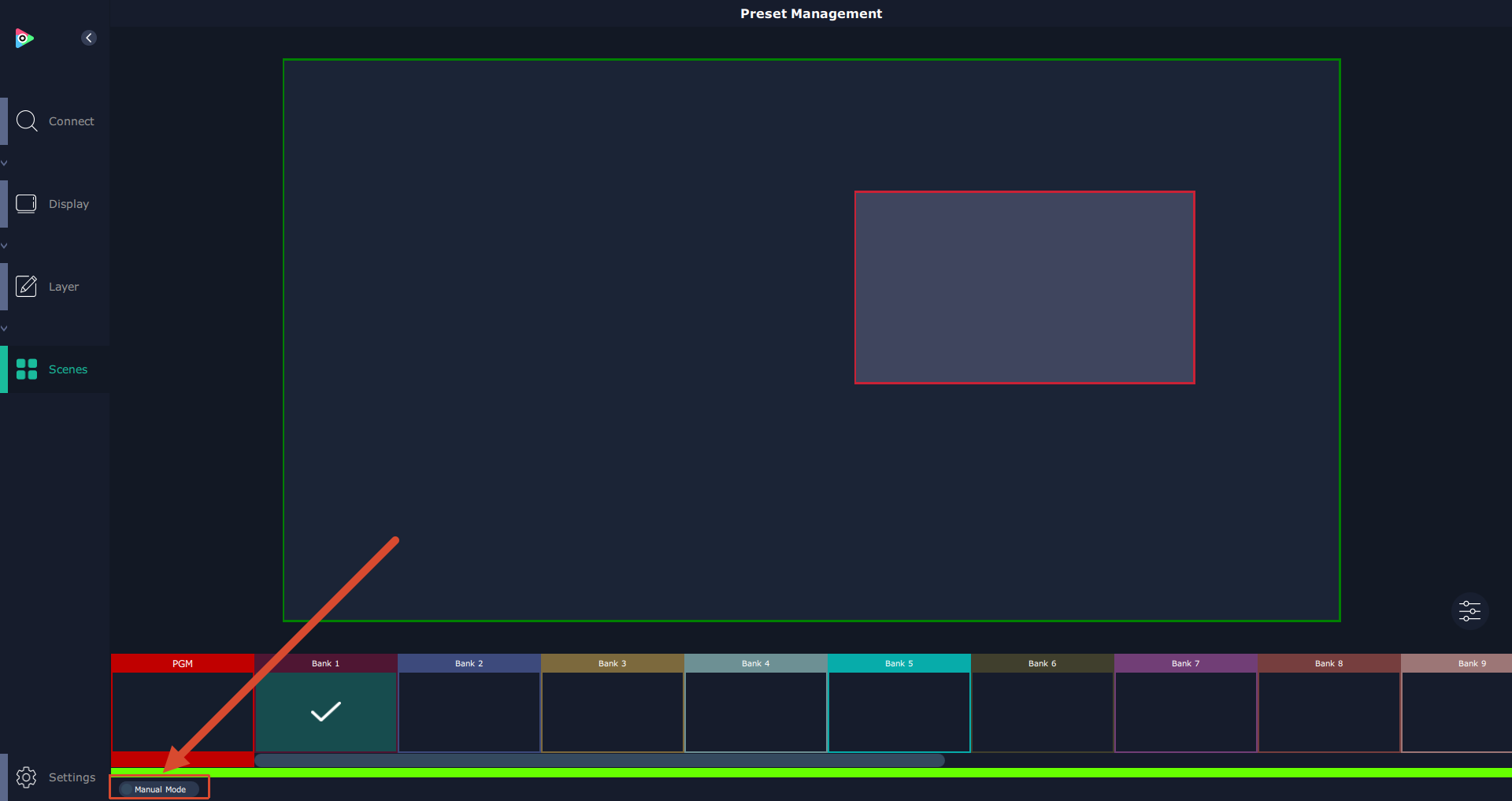
Mode Switch

Schedule Mode

Schedule Mode automatically recalls scenes according to a scheduled timetable.

To configure scheduled playback:

  1. Enable Schedule Mode.
  2. Select the Loop Mode.
  3. Select the desired scene Bank.
  4. Set the start and end times.
  5. Click OK.

Schedule Mode

To edit or delete an existing schedule, click the corresponding Edit or Delete icon, then enable the schedule.

Bank List

Manual Mode

Switch to Manual Mode, select a scene, then click the properties icon.

The following options are available:

  • Take Setting
  • Preset Name
  • Script
  • Hotkey
Take Setting

Click CUT to switch from PVW to PGM immediately.

Page
ItemIllustrationDescription
Save PageSelect a preset, click Save Page, then select Page X to save the preset to that page. A page with a saved preset is displayed in green.
Load PageClick Load Page, select a saved preset, and load it. The selected page turns red.
Script
  1. In the script page, enter the File Path and File Name, and click Save. The file appears under Load Script.
  2. Click Load icon to load the file into XPOSE.
  3. Click Delete iconto delete the saved script.

Preset Name

Rename the current scene and assign a scene label color.

Hotkey

Displays the keyboard shortcuts available for scene switching.

3.3XPOSE APP

For APP download, please check rgblink official website > support page > proAV/proEvents > Software.

📢  Important

The device and phone must be in the same network.

Q16pro Gen2 support to load scene via XPOSE APP.

3.3.1 Connect Q16pro Gen2 to a phone

Connect Q16pro Gen2 to a phone through XPOSE APP using either of the following methods:

  • Method 1: Wi-Fi connection
  • Method 2: Direct connection

Before connecting, install XPOSE APP on your phone.

  1. Open XPOSE APP.
  2. Tap Search.

  1. Select Q16pro Gen2.

  1. Enter the IP address of Q16pro Gen2.
  2. Tap OK.

3.3.2 Load Scene

The scene list uses different colors to indicate scene status:

Indicator ColorStatus
RedCurrent scene
GreenSaved scene
WhiteEmpty scene

To load a scene:

  1. Select a group on the left list.
  2. Select the required scene.

For example, if the current scene is Scene 2 in Group 1, select 1 to switch to Scene 1 in Group 1.

To load a scene from another group, select the required group first, then select the required scene.

3.4XTOOL


Current XTOOL Version:1.0.2.59
For software download, please check rgblink official website > support page > proAV/proEvents > Software.

XTOOL is used to upgrade device firmware. It also displays the device connection status, device information, and firmware upgrade progress.

3.4.1XTOOL_Installation

Launch the Installer

Double-click the installer on the desktop.

When the language selection dialog appears, choose the desired language and click OK.

Start Installation

When the Setup Wizard opens, click Next> to continue.

Select the Installation Location

Click Browse... to choose the installation directory, then click Install.

📢  Important

On Windows 7 or later, administrator privileges are required when installing to the system drive (C:).

Install the Virtual Com Port Driver

During installation, the Virtual Com port driver installer opens automatically.

  • Click Next >.

  • Review the installation settings, then click Install.

  • When installation is complete, click Finish.

Complete the Installation

After the multimedia components are installed, the XTOOL Setup Wizard resumes.

Click Finish to complete the installation.

3.4.2XTOOL_Upgrade

Before You Upgrade

Upgrade Package

Before upgrading, download the following files from the RGBlink official website:

  • XTOOL installation package
  • Device firmware package
Upgrade Methods

XTOOL supports the following upgrade methods:

  • Serial Upgrade: Connect the device to the computer using a serial cable.
  • Network Upgrade: Connect the device to the computer using an Ethernet cable.

Using XTOOL


🚨  Warning
Do not disconnect the device or turn off its power during the firmware upgrade.  

  • Double-click the XTOOL icon to launch the software.

  • Check the connection status in the lower-left corner of the main interface.
    • Green indicates that the device is connected successfully.
    • Red indicates that the device is disconnected or the connection has failed.
  • Verify the device model and serial number in the lower-right corner of the main interface.

Serial Upgrade
  1. Connect the device to the computer using a serial cable.
  2. Click Connection. In the dialog box, select the Equipment series, choose Serial Comm, and then click Confirm.

  1. After the device is connected successfully, click Choose File and select the .bin firmware file.

  1. Click All to select the firmware modules to be upgraded.

📢 Notes

After you click All, XTOOL automatically compares the firmware versions on the device with those in the upgrade package.

-  Files with the same version are not selected. 
-  Files with different versions are selected automatically for upgrade.

  1. Click Upgrade. When the firmware upgrade confirmation dialog box appears, click Confirm to start the upgrade.
📢  Notes

During the upgrade, you can monitor both the individual module progress and the overall upgrade progress on this page.  

  1. After the upgrade is complete, the firmware upgrade completed dialog box appears. Click Confirm.
  2. Power off the device, and then power it on again.
Network Upgrade
📢 Notes

Before upgrading over the network, make sure that the device and the computer are on the same local network and that their IP addresses are in the same subnet.  

  1. Connect the device to the computer using an Ethernet cable.
  2. Click Connection. In the dialog box, select the Equipment series, choose Net Comm, and then click Confirm.

  1. After the device is connected successfully, click Choose File and select the .bin firmware file.

  1. Click All to select the firmware modules to be upgraded.

📢 Notes

After you click All, XTOOL automatically compares the firmware versions on the device with those in the upgrade package.

-  Files with the same version are not selected. 
-  Files with different versions are selected automatically for upgrade.

  1. Click Upgrade. When the firmware upgrade confirmation dialog box appears, click Confirm to start the upgrade.
📢 Notes

During the upgrade, you can monitor both the individual module progress and the overall upgrade progress on this page.  

  1. After the upgrade is complete, the Firmware Upgrade Completed dialog box appears. Click Confirm.
  2. Power off the device, and then power it on again.

4Upgrade

Q16pro Gen2 models support upgrades through XTOOL.

View 3.4.2 XTOOL_Upgrade for upgrade instructions.

5Technical Support

6Revision History

VersionDateDescriptionAuthor
V2.32026-09-081. Add XPOSE APP guidance 2. Update XPOSE operation (V 2.0.8.17) 3. Upgrade XTOOL_Upgrade guidance 4. Publish documentation online, add details.ZYL
V2.12025-09-24Add order codes of the 8-CH HDMI input and output modules.FMY
V2.22025-09-04Clarified the required chassis size and modules of the 16 layer roaming and 8+8 layer outputFMY
V2.02025-08-20Update the included accessoriesFMY
V1.92025-06-25Verify the product codesFMY
V1.82025-03-27Change product codesFMY
V1.72024-08-15Revise accessories included in the boxYJ
V1.62024-07-23Upgrade point: support 16 layersYJ
V1.52024-02-02Add Dante configuration on XPOSEYJ
V1.42023-12-20Add optional I/O modulesYJ
V1.32023-10-09Add XTOOL upgrade guidanceYJ
V1.22023-08-231. Add 2U, 4U front panel description; 2. Add input & output interface description in XPOSE operation; 3. Add notice of layer managementYJ
V1.12023-07-21Add 2U dimension drawingYJ
V1.02023-03-01First releaseYJ

12Declarations

FCC/Warranty

Federal Communications Commission (FCC) Statement

This equipment has been tested and found to comply with the limits for a class A digital device, pursuant to Part 15 of the FCC rules. These limits are designed to provide reasonable protection against harmful interference when the equipment is operated in a commercial environment. This equipment generates, uses, and can radiate radio frequency energy and, if not installed and used in accordance with the instruction manual, may cause harmful interference to radio communications. Operation of this equipment in a residential area may cause harmful interference, in which case the user will be responsible for correcting any interference.

Guarantee and Compensation

RGBlink provides a guarantee relating to perfect manufacturing as part of the legally stipulated terms of guarantee. On receipt, the purchaser must immediately inspect all delivered goods for damage incurred during transport, as well as for material and manufacturing faults. RGBlink must be informed immediately in writing of any complains.

The period of guarantee begins on the date of transfer of risks, in the case of special systems and software on the date of commissioning, at latest 30 days after the transfer of risks. In the event of justified notice of compliant, RGBlink can repair the fault or provide a replacement at its own discretion within an appropriate period. If this measure proves to be impossible or unsuccessful, the purchaser can demand a reduction in the purchase price or cancellation of the contract. All other claims, in particular those relating to compensation for direct or indirect damage, and also damage attributed to the operation of software as well as to other service provided by RGBlink, being a component of the system or independent service, will be deemed invalid provided the damage is not proven to be attributed to the absence of properties guaranteed in writing or due to the intent or gross negligence or part of RGBlink.

If the purchaser or a third party carries out modifications or repairs on goods delivered by RGBlink, or if the goods are handled incorrectly, in particular if the systems are commissioned operated incorrectly or if, after the transfer of risks, the goods are subject to influences not agreed upon in the contract, all guarantee claims of the purchaser will be rendered invalid. Not included in the guarantee coverage are system failures which are attributed to programs or special electronic circuitry provided by the purchaser, e.g. interfaces. Normal wear as well as normal maintenance are not subject to the guarantee provided by RGBlink either.

The environmental conditions as well as the servicing and maintenance regulations specified in this manual must be complied with by the customer.

Operators Safety Summary

The general safety information in this summary is for operating personnel.

Do Not Remove Covers or Panels

There are no user-serviceable parts within the unit. Removal of the top cover will expose dangerous voltages. To avoid personal injury, do not remove the top cover. Do not operate the unit without the cover installed.

Power Source

This product is intended to operate from a power source that will not apply more than 230 volts rms between the supply conductors or between both supply conductor and ground. A protective ground connection by way of grounding conductor in the power cord is essential for safe operation.

Grounding the Product

This product is grounded through the grounding conductor of the power cord. To avoid electrical shock, plug the power cord into a properly wired receptacle before connecting to the product input or output terminals. A protective-ground connection by way of the grounding conductor in the power cord is essential for safe operation.

Use the Proper Power Cord

Use only the power cord and connector specified for your product. Use only a power cord that is in good condition. Refer cord and connector changes to qualified service personnel.

Use the Proper Fuse

To avoid fire hazard, use only the fuse having identical type, voltage rating, and current rating characteristics. Refer fuse replacement to qualified service personnel.

Do Not Operate in Explosive Atmospheres

To avoid explosion, do not operate this product in an explosive atmosphere.

Installation Safety Summary

Safety Precautions

For all device installation procedures, please observe the following important safety and handling rules to avoid damage to yourself and the equipment.

To protect users from electric shock, ensure that the chassis connects to earth via the ground wire provided in the AC power Cord.

The AC Socket-outlet should be installed near the equipment and be easily accessible.

Unpacking and Inspection

Before opening device shipping box, inspect it for damage. If you find any damage, notify the shipping carrier immediately for all claims adjustments. As you open the box, compare its contents against the packing slip. If you find any shortages, contact your sales representative.

Once you have removed all the components from their packaging and checked that all the listed components are present, visually inspect the system to ensure there was no damage during shipping. If there is damage, notify the shipping carrier immediately for all claims adjustments.
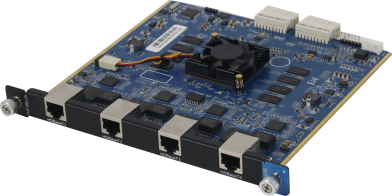
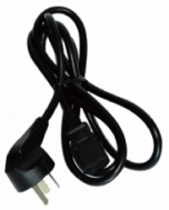
Site Preparation

The environment in which you install your device should be clean, properly lit, free from static, and have adequate power, ventilation, and space for all components.

About Us / Find Support

Xiamen RGBlink Science & Technology Co., Ltd. designs and manufactures professional video processing, switching, streaming and LED display control products for live events, broadcast, education and fixed installations.

Need help?

Choose one of the following support options:

  • AI Support Search (Recommended): Visit Support > Support proStream/proAV/proEvents on the RGBlink official website and ask the RGBlink AI Bot for quick answers.
  • FAQs: Visit Support > Support proStream/proAV/proEvents on the RGBlink official website and browse Knowledge Menu > FAQ.
  • Contact Technical Support: Visit the Technical Support page of this manual or the RGBlink official website for our contact details.

Document image

RGBlink

www.rgblink.com

© Copyright Xiamen RGBlink Science & Technology Co Ltd