Export PDF

RGBlink
D8e

User Manual

D8e

D8e User Manual

130-0008-06-0

RGBlink

www.rgblink.com

November 2026

1D8e Quick Start

Thank you for choosing RGBlink D8E.

This Quick Start covers the installation, connections, and basic operations to help you set up and start using the device quickly.

Read this guide carefully and follow the instructions before using the device.

2About Your Product

The RGBlink D8 Series is designed to deliver high-quality video processing solutions.

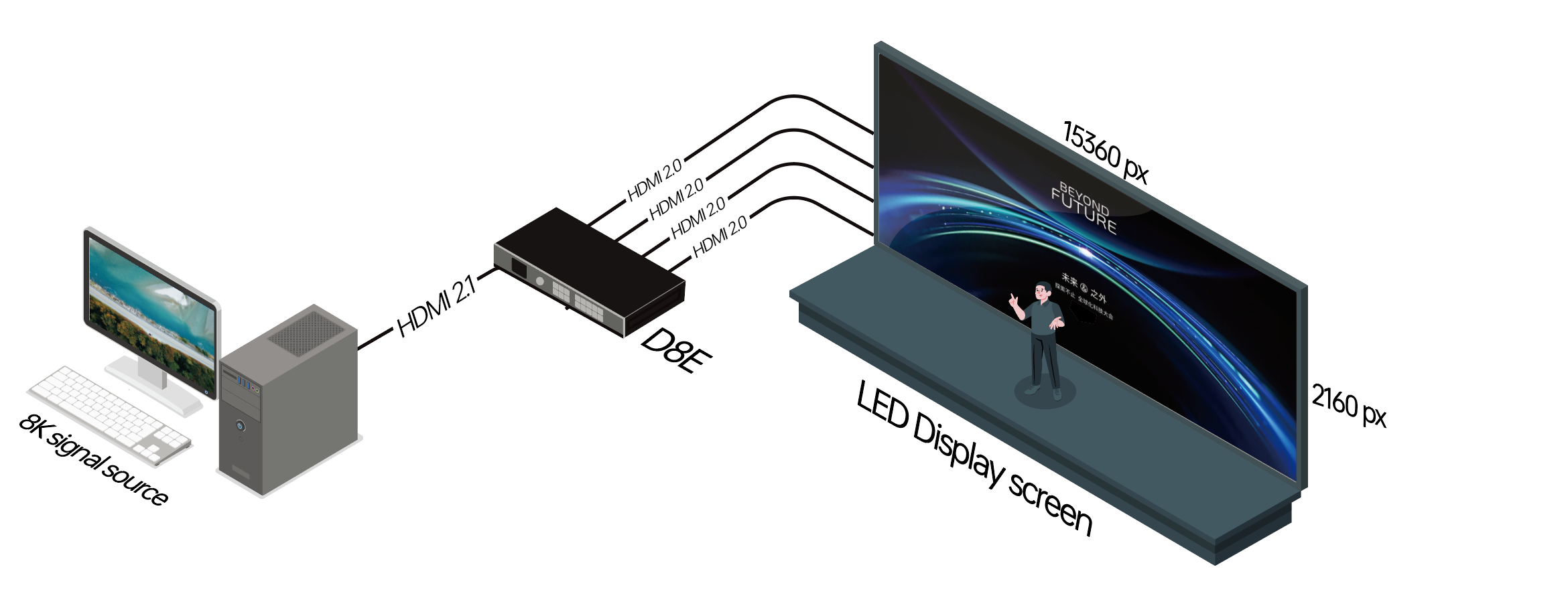
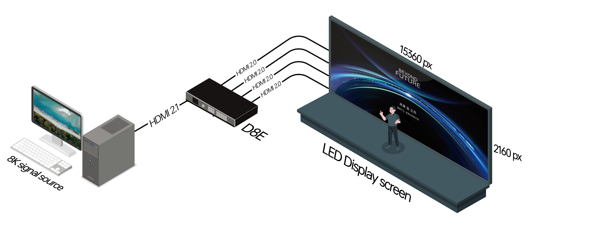
As the flagship 8K video processor in the D8 Series, D8E supports video processing up to 8K@60 and is designed for large LED displays, professional presentations, and high-end audiovisual applications. It delivers high-resolution and reliable video processing for demanding applications.

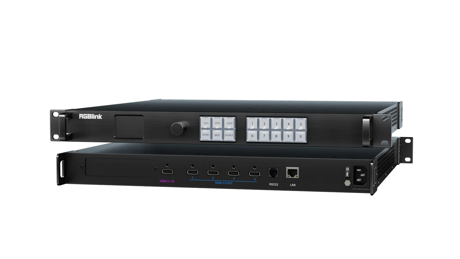
D8E features one HDMI 2.1 input and four HDMI 2.0 outputs for 8K signal processing and multi-display output. The device also features a 2-inch LCD for system information and front-panel shortcut buttons for intuitive device control and status monitoring.

3In the Box

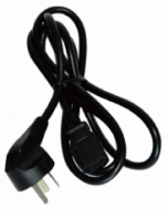
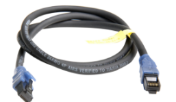
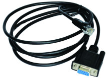
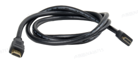
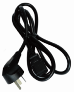
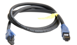
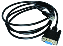
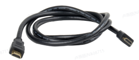
1×AC Power Cable1×Network Cable1×DB9 to RJ11 Cable1×HDMI 2.1 Cable
📢  Notes

AC power cable supplied according to destination market.  

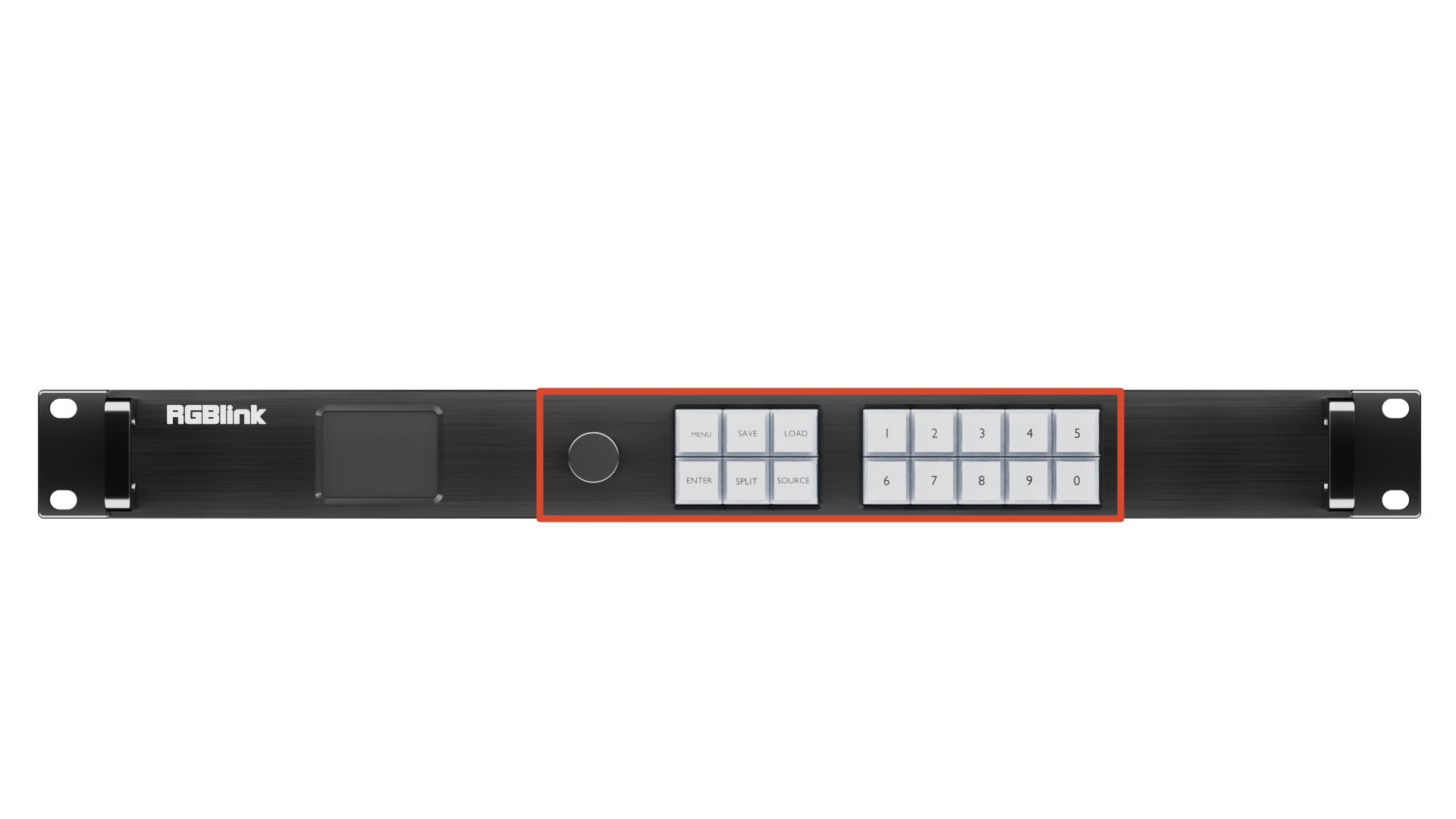
4Front Panel

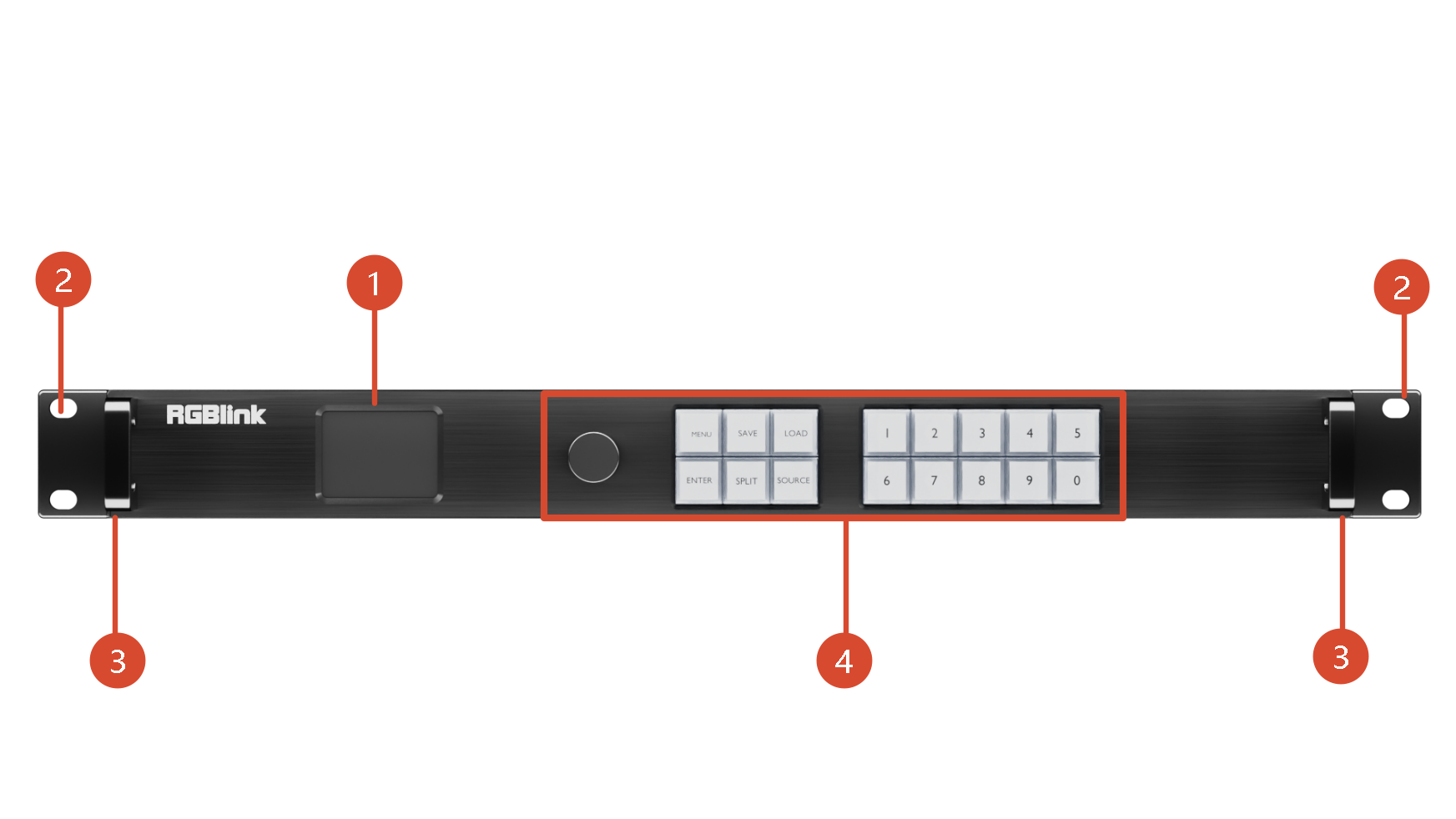
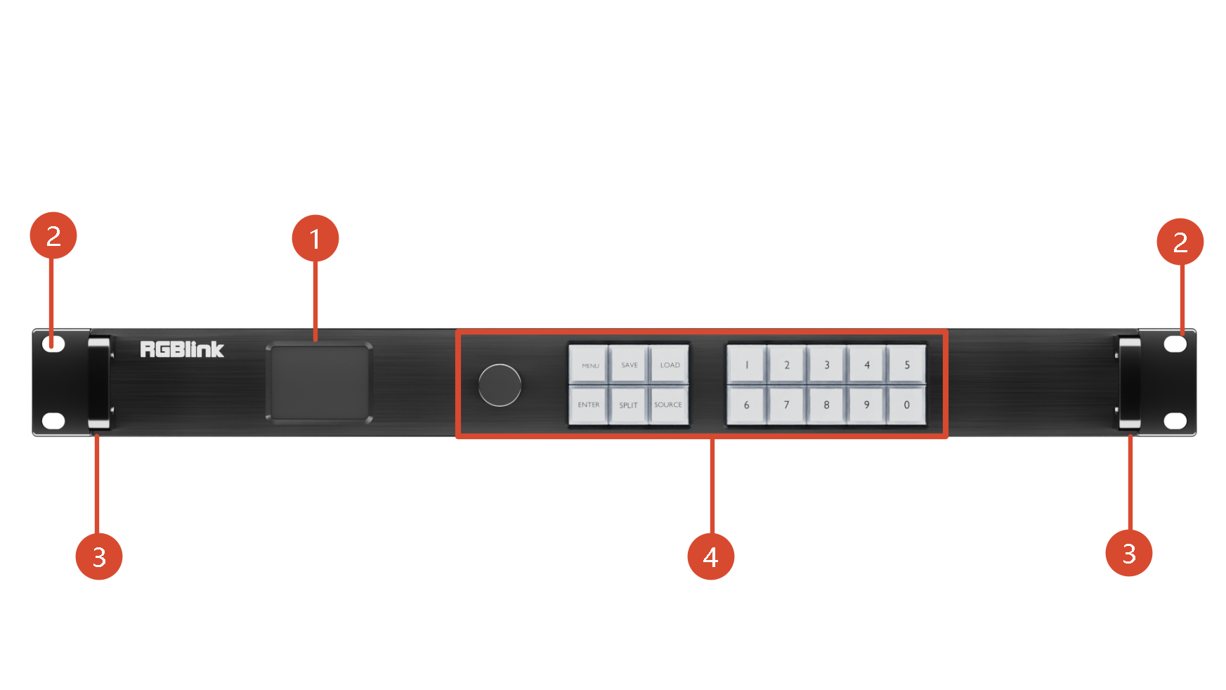
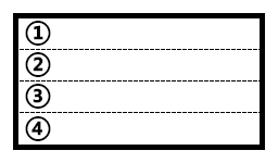
NO.NameDescription
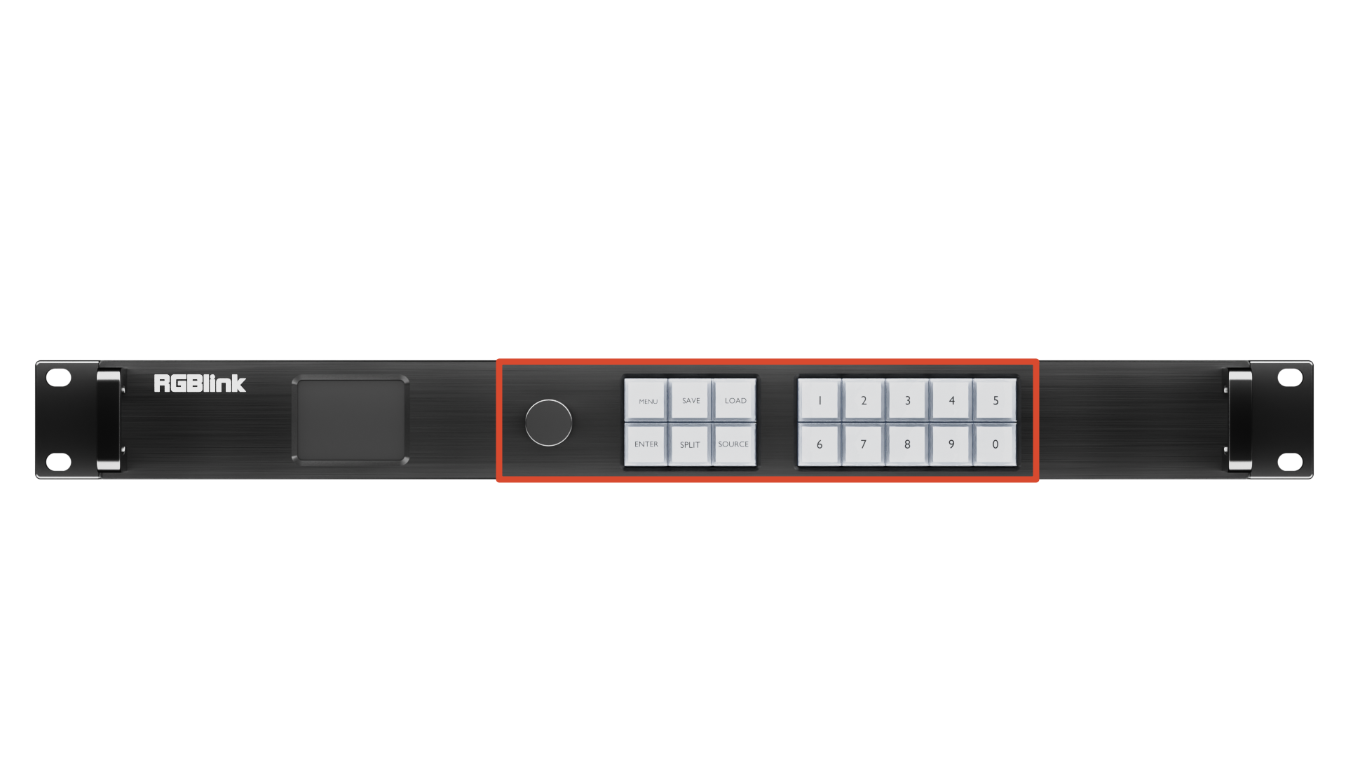
①Touch Screen4-inch LCD touch screen allows you to directly control D8, which optimizes the user experience.
②Rack Mount EarsUse with the load-bearing screws to fix device on the rack.
③HandlesFor carrying device.
④Shortcut Key ControlFor menu operation.

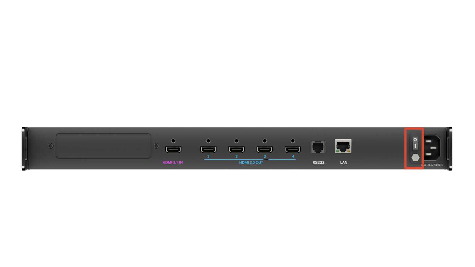
5Rear Panel

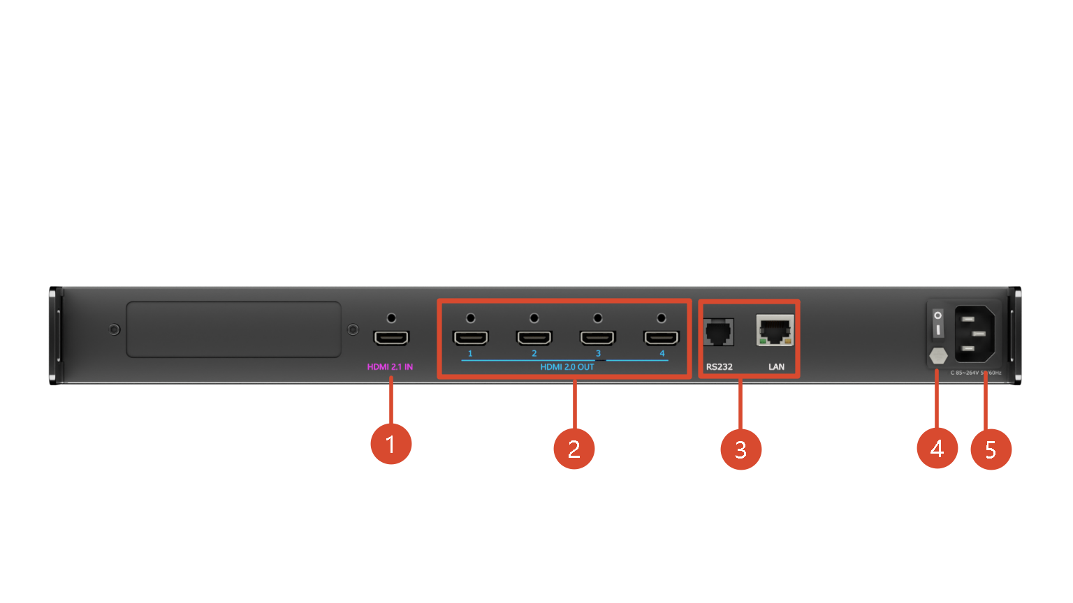
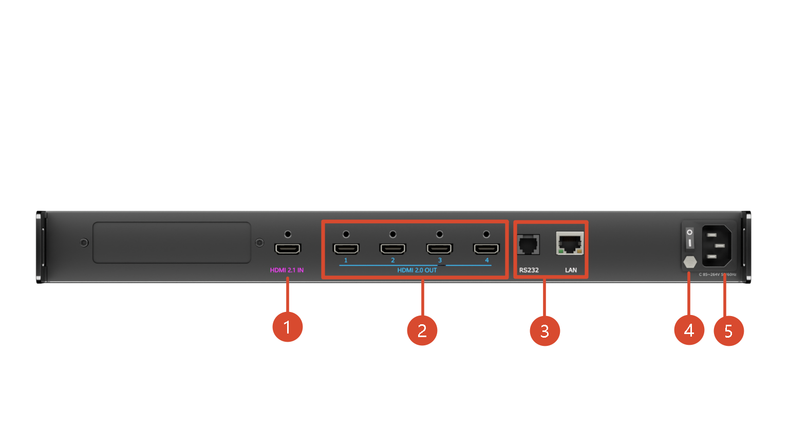
NO.NameDescription
①Input InterfaceStandard with 1× HDMI 2.1 Input Interface
②Output InterfaceStandard with Quad HDMI 2.0 Output Ports
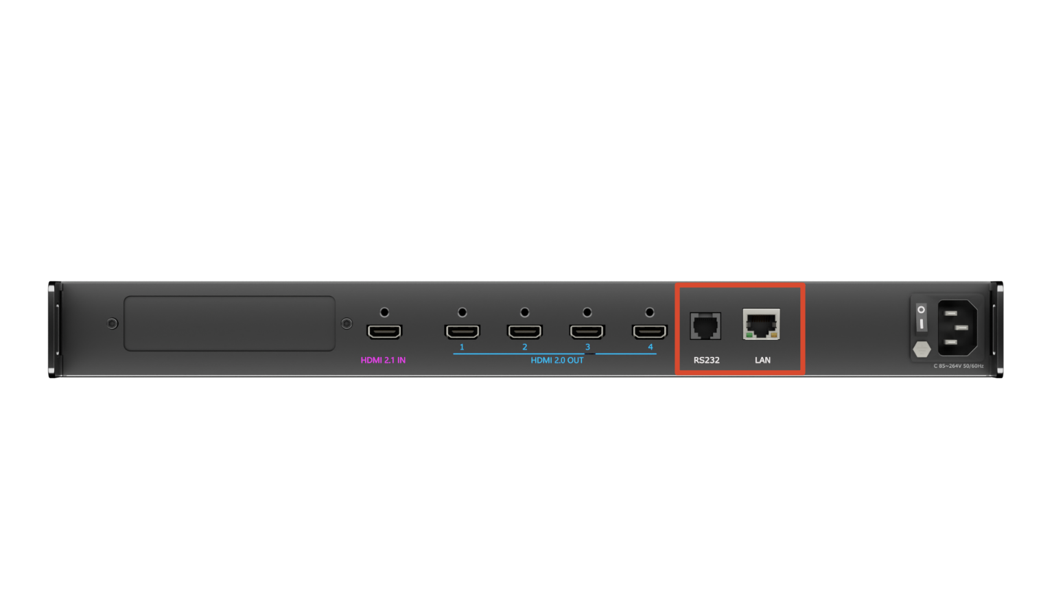
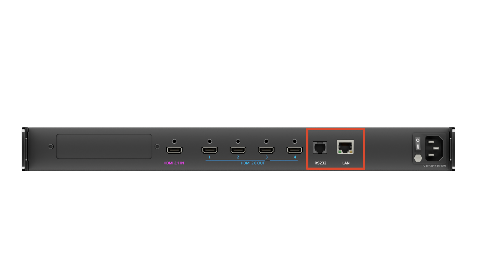
③Communication InterfaceStandard with 1×RS 232 Serial Port and 1×LAN Network Port
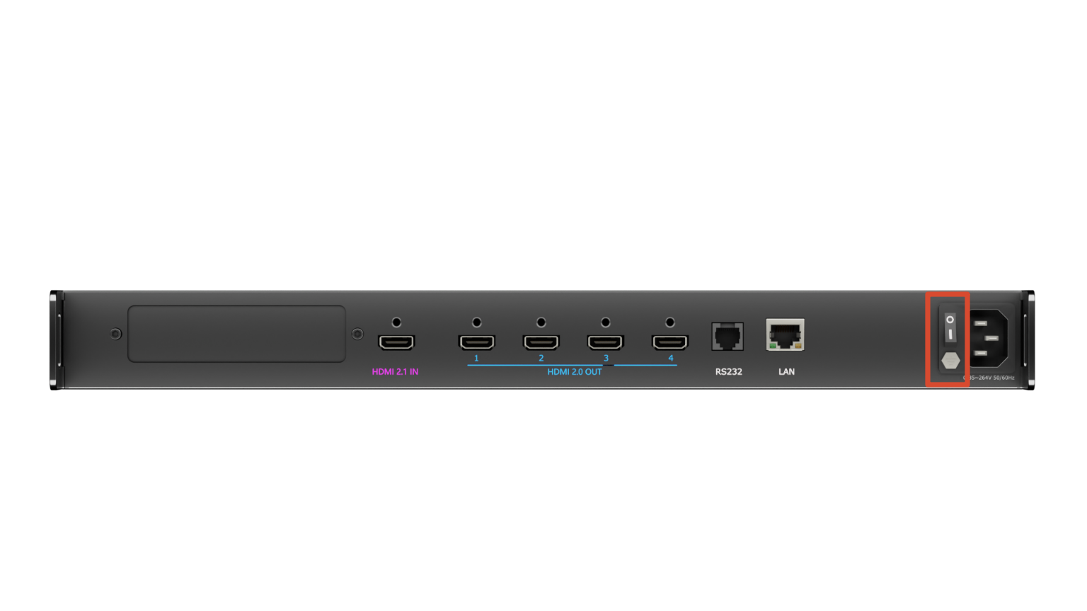
④Power SwitchPower on or off the device
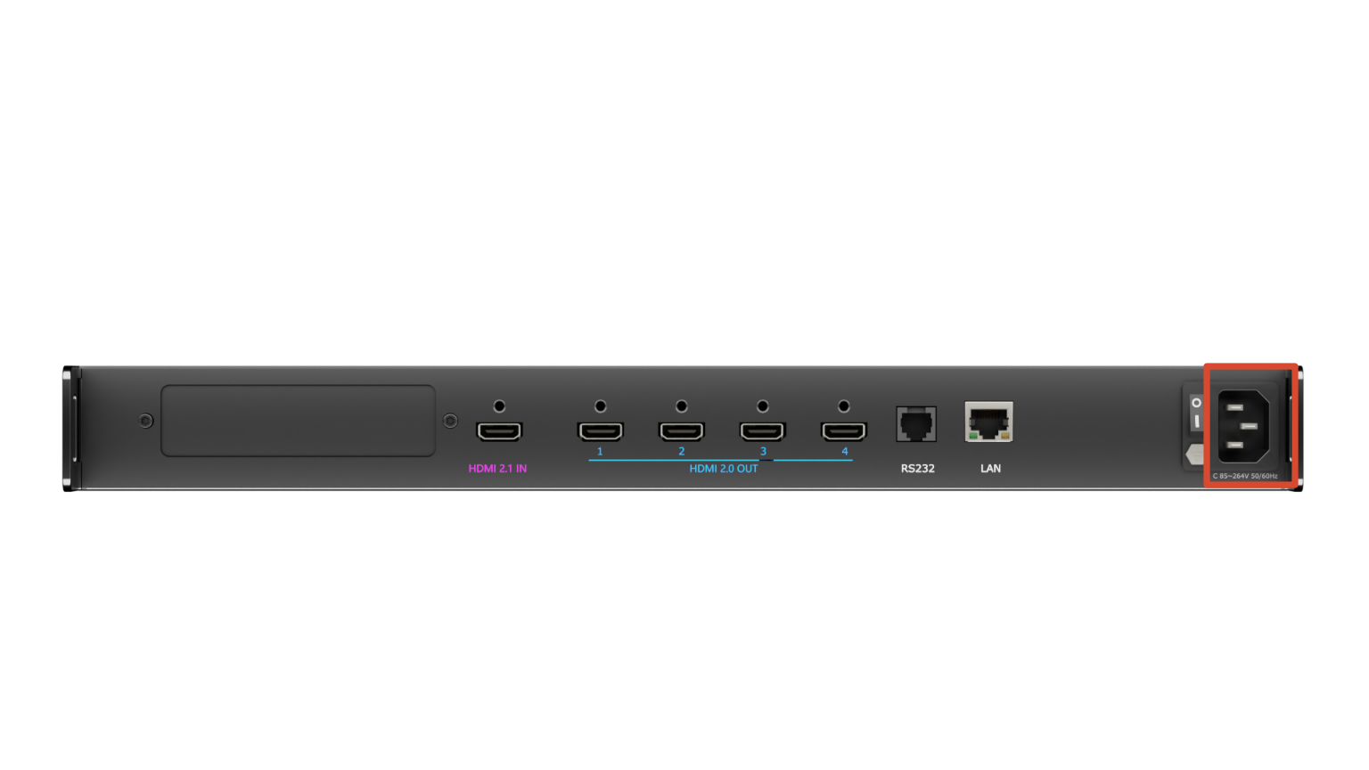
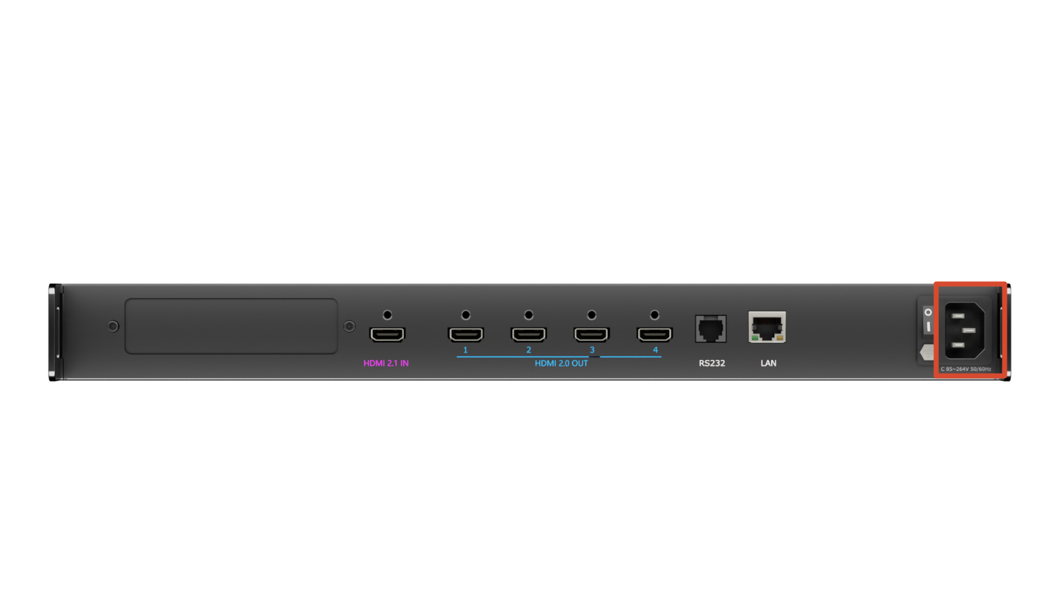
⑤Power InterfaceConnect standard power cable to device and plug into wall socket

6Install Your Product

Connecting Power

Use the supplied power cable to connect the D8 to an AC power outlet.

Connecting Video Sources

D8 features two HDMI 2.1 inputs and four HDMI 2.0 outputs.

  • Connect video sources to the HDMI input ports.
  • Connect display devices to the HDMI output ports.
📢  Important

Ensure all cables are securely connected.

Connecting a Control Device

D8 supports serial and network communication. You can manage and remotely control the device by running XPOSE 2.0 on a computer. For details, see the XPOSE 2.0 manual.

  • Serial Communication: Connect RS232 port to the computer using a serial cable.
  • Network Communication: Connect LAN port to the computer using an Ethernet cable.

Powering On

After all connections are complete:

  1. Set the rear-panel power switch to ON.
  2. Wait for the device to start up.
  3. The home screen displays.

7Use Your Product

Once installation and setup are complete, refer to this chapter for operating instructions.

The interfaces, images, and illustrations in this chapter are for reference only. Actual displays may vary by version. Please refer to the actual interface on your device.

8Menu

D8E belongs to the D8 series. Its main menu is consistent with D8 and D8 PLUS, except for interface differences.

After startup, the LCD touchscreen displays the home screen, including the main Menu, the IP address and device serial number (SN).

The main menu provides access to the following functions: Device, Settings, Load, Language, Version, and Input.

Please use the front-panel shortcut key controls to operate the main menu.

Shortcut Key Controls

KeyFunction
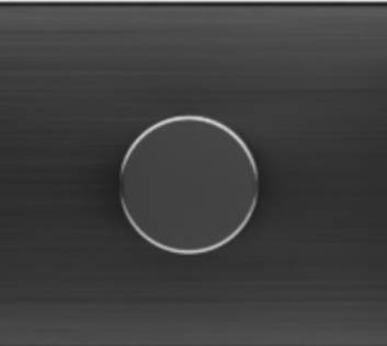
KnobSelect and confirm menu options
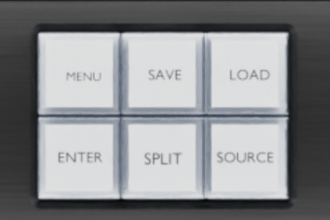
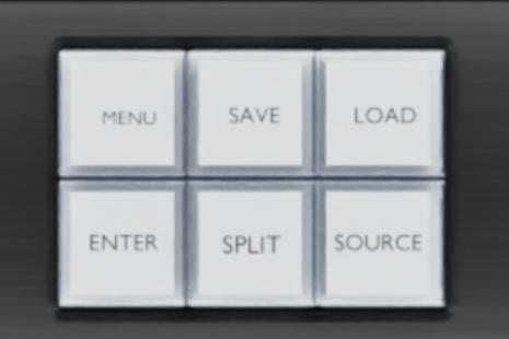
Function ButtonsMENU: Open the menu ENTER: Confirm SAVE: Save a scene SPLIT: Select and configure split screesn LOAD: Load a scene SOURCE: Signal source
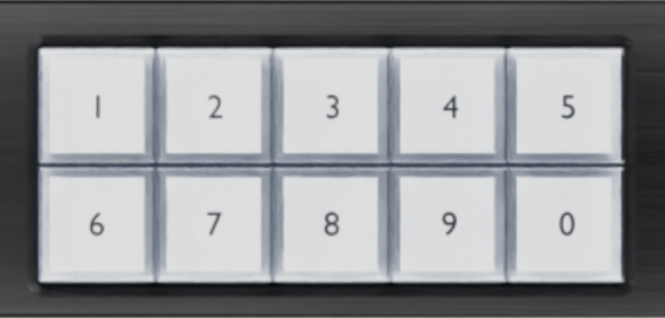
Number KeysEnter numbers

Device

Select Device on the home screen.

  • Views the current input and output status, including the video resolution of each signal.
  • IP settings:
    • DHCP: Disabled by default. Enable this option to automatically obtain an IP address.
    • Parameter Settings: Manually configure the IP address, gateway, and subnet mask. After saving the settings, network control and upgrades can be performed.

Settings

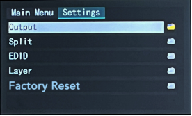
Select Settings on the home screen.

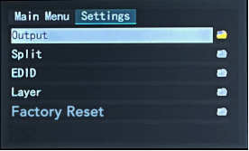
This menu provides access to output resolution, split (video wall layout), EDID management, layer settings, and factory reset.

Settings Page

Output

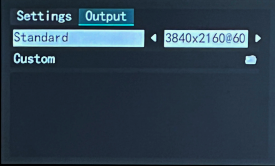
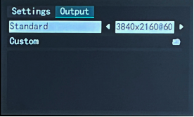
Select Settings > Output to configure the output resolution.

D8 supports both Standard and Custom resolution modes.

Output Page

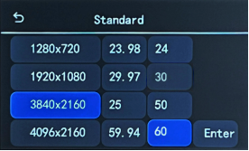
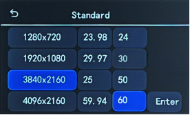
Standard Resolution Mode
  1. Select Standard.
  2. Select the desired resolution and frequency.
  3. Select Enter to save.
  4. The device returns to the previous page, and the selected resolution is displayed.

Standard Resolution Mode

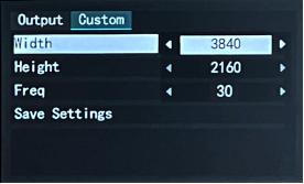
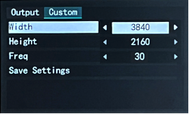
Custom Resolution Mode
  1. Select Custom.
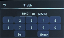
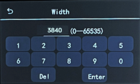
  2. Enter the Width, Height, and Freq (Frequency) using the numeric keypad.
  3. Select Save Settings to save.
  4. The configured resolution is displayed under Device > Output

Custom Resolution ModeNumeric Keypad

Split

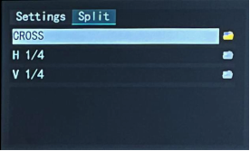
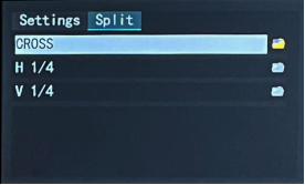
Select Settings > Split.

D8 provides three split layouts for different display configurations.

Split Page

LayoutDescriptionIllustration
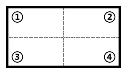
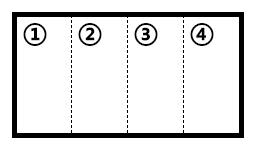
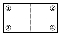
Cross (Default)Four-display 2 × 2 layout
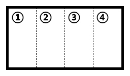
H 1/4Four displays arranged horizontally
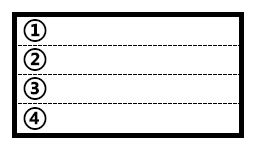
V 1/4Four displays arranged vertically
Cross

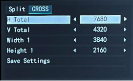
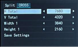
Select CROSS to configure a 2 × 2 layout.

Enter the total display width and height. D8 automatically calculates the output area for each display.

For example:

  • Total Width: 7680
  • Total Height: 4320
  • Display Width: 3840
  • Display Height: 2160

Enter the values using the numeric keypad, then Select Save Settings > Confirm.

Cross Page

H 1/4

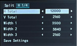
Select H 1/4.

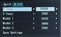
Enter the total display width and height, then specify the width of each display.

For example:

  • Total Width: 12000
  • Total Height: 2160

Display widths:

  • Display 1: 3500
  • Display 2: 3840
  • Display 3: 2160
  • Display 4: 2500 (calculated automatically)

The display height is the same as the total height (2160) and does not need to be configured.

Enter the values using the numeric keypad, then Select Save Settings > Confirm.

H 1/4 Page

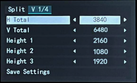
V 1/4

Select H 1/4.

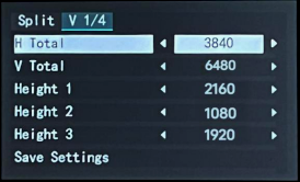
Enter the total display width and height, then specify the height of each display.

For example:

  • Total Width: 3840
  • Total Height: 6480

Display heights:

  • Display 1: 2160
  • Display 2: 1080
  • Display 3: 1920
  • Display 4: 1320 (calculated automatically)

The display width is the same as the total width (3840) and does not need to be configured.

Enter the values using the numeric keypad, then Select Save Settings > Confirm.

V 1/4 Page

EDID

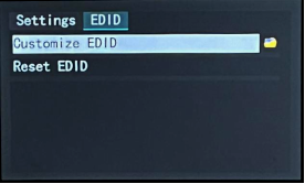
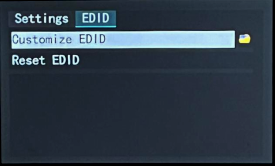
Select Settings > EDID.

EDID (Extended Display Identification Data) defines the display capabilities reported to the video source, ensuring output compatibility.

D8 supports Customize EDID and Reset EDID.

EDID Page

Customize EDID

Select Customize EDID.

  1. Enter the Width, Height, and Refresh Rate using the numeric keypad.
  2. Select Apply > Confirm.
  3. The device returns to the previous page after the settings are applied.
  4. After configuring the EDID on D8, configure the video source to match the same output resolution.

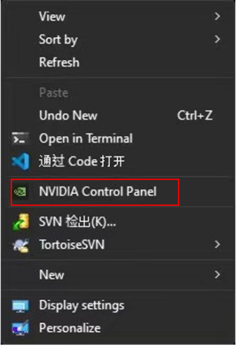
Using Windows system and an NVIDIA graphics card as an example:

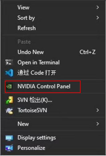
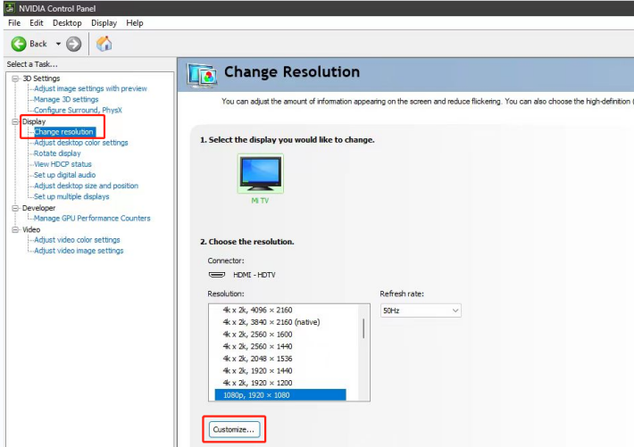
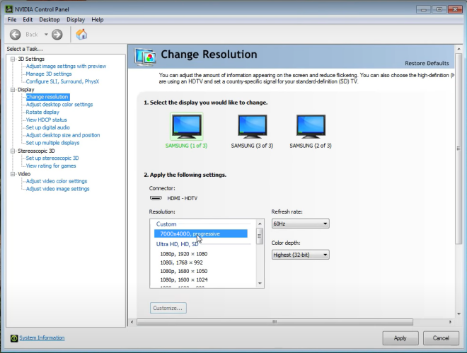
  1. Set the resolution on graphics card. Taking NVIDIA as an example: Right-click on the desktop, then select NVIDIA Control Panel.

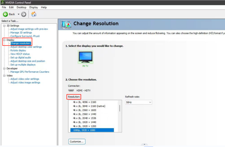
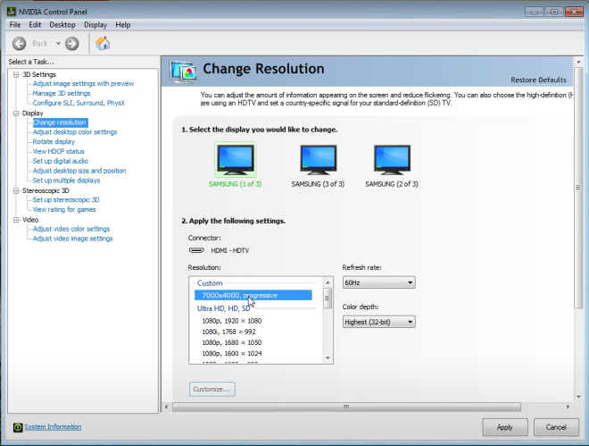
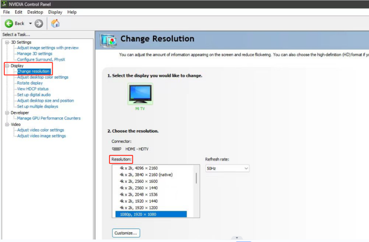
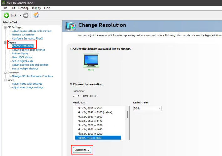
  1. Click Display > Change Resolution.

Firstly, check if 7000x4000@60 can be found in the drop-down list. Select this resolution directly if there is 7000x4000@60 without needs to follow Step 3 to Step 5 to customize resolution.

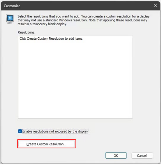
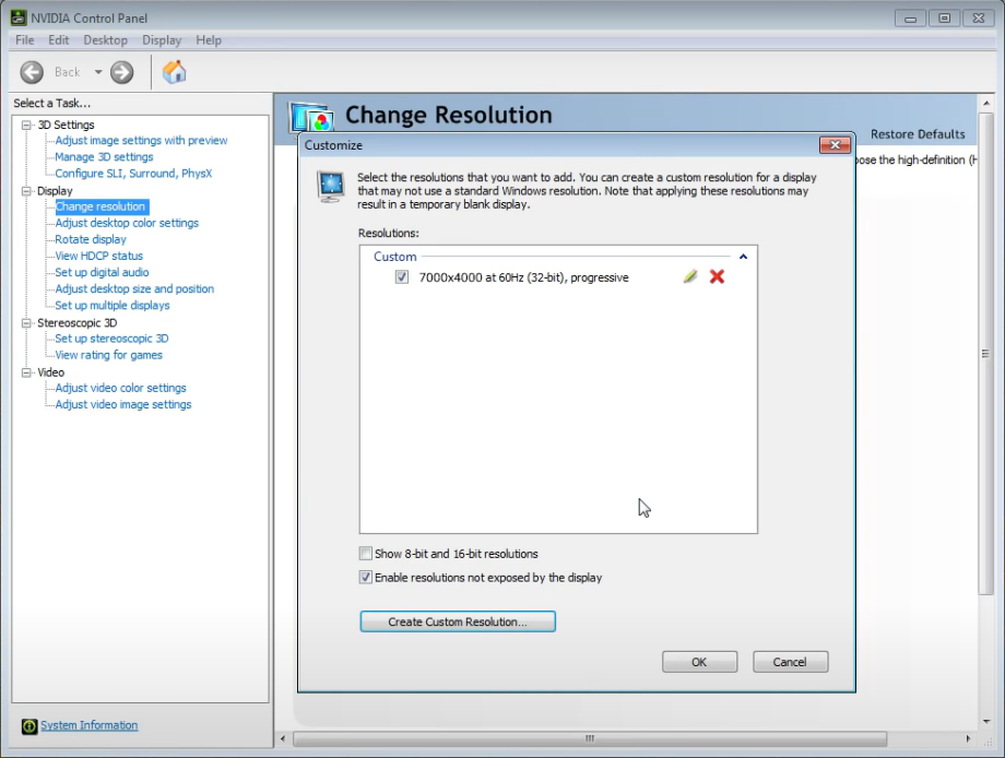
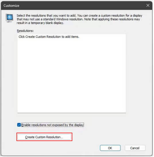
If 7000x4000@60 cannot be found, please click Customize and then follow Step 3 to Step 5 for resolution setting.

  1. Click Create Custom Resolution.

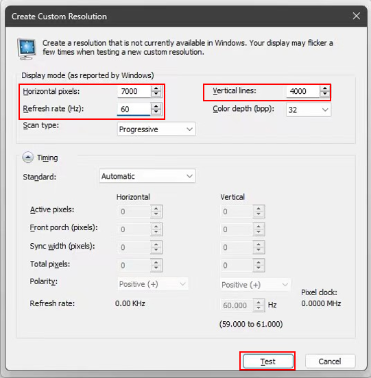
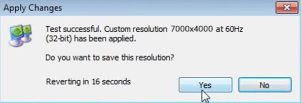
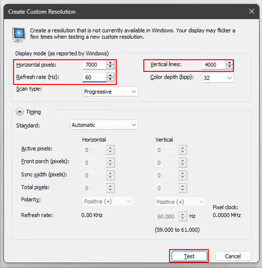
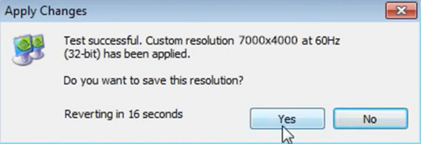
  1. Customize resolution:Enter 7000 in the Horizontal pixels , 4000 in the Vertical lines and 60 in the Refresh rate . Enter the custom resolution values, then click Test . Select Yes in the pop-up to apply the custom resolution.

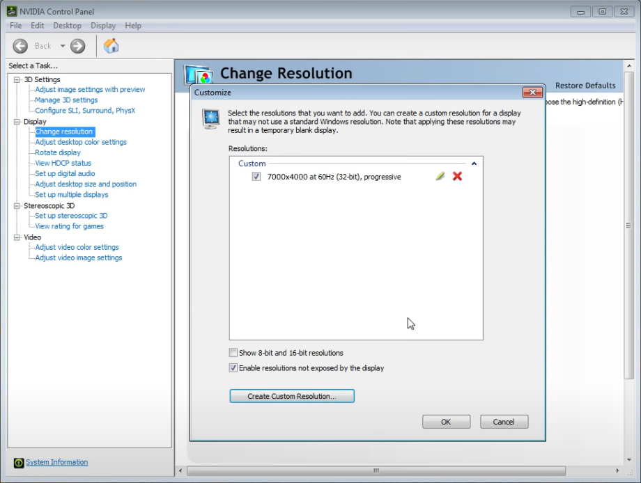
  1. Then the set resolution will be displayed in Custom . Click OK and check the resolution in Change Resolution interface.

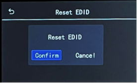
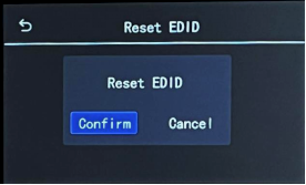
Reset EDID

Select Reset EDID, then Select Confirm.

Reset EDID Page

📢  Notes

Resetting EDID restores the default settings. This action cannot be undone.  

Layer

Select Settings > Layer.

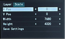
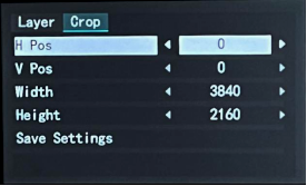
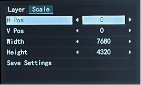
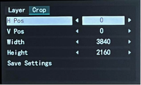
D8E supports layer Scaling and Cropping.

  1. Select Scale or Crop.
  2. Enter the Horizontal Position, Vertical Position, Width, and Height using the numeric keypad.
  3. Select Save Settings > Confrim.

The device returns to the previous page after the settings are saved. Scale PageCrop Page

Factory Reset

Select Settings > Factory Reset.

This function restores D8 to its factory default settings.

📢  Notes

Performing a factory reset restores the parameters and resolutions to their default values. EDID settings are not affected.  

Load Presets

Select Load on the home screen.

D8 supports up to 16 saved banks.

📢  Important

Banks must be created and saved in XPOSE before they can be loaded from D8.  

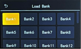
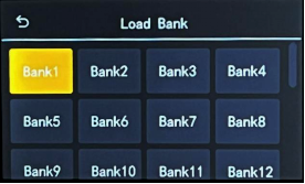
Load Bank Page

Bank status:

  • Green: Saved
  • Yellow: Selected
  • No background: Empty

To load a bank:

  • Select the desired bank.
  • When the confirmation message appears, Select Confirm.

Language

Select English on the home screen.

Select English or 简体中文. The interface switches to the selected language immediately.

Version

Select Version on the home screen.

This page displays the firmware versions of the panel and main board.

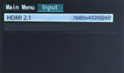
Input

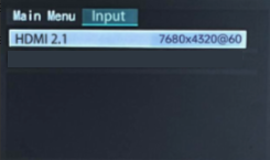
Select Input on the home screen.

This page displays all input ports and their current resolutions.

Select an input source to switch the active input.

The connected display updates automatically to show the selected source.

If no signal is connected, "NO" is displayed on the page.

9XPOSE 2.0

**Current XPOSE 2.0 Version:2.0.8.17**

Device Connection

Connect the device's RS232 port to the computer's RS232 port using a DB9-to-RJ11 serial cable.

If the computer does not have an RS232 port, use a DB9-to-USB adapter.

Using XPOSE 2.0

Refer to the XPOSE 2.0 section in the D8E_User Manual for operation instructions.

10D8E_User Manual

Thank you for choosing RGBlink D8E.

This manual provides information on the device features, installation and operation. A Glossary is provided at the end of this manual for reference.

Before using the device for the first time, please read this manual carefully to ensure safe and proper use of the product.

11Declarations

FCC/Warranty

Federal Communications Commission (FCC) Statement

This equipment has been tested and found to comply with the limits for a class A digital device, pursuant to Part 15 of the FCC rules. These limits are designed to provide reasonable protection against harmful interference when the equipment is operated in a commercial environment. This equipment generates, uses, and can radiate radio frequency energy and, if not installed and used in accordance with the instruction manual, may cause harmful interference to radio communications. Operation of this equipment in a residential area may cause harmful interference, in which case the user will be responsible for correcting any interference.

Guarantee and Compensation

RGBlink provides a guarantee relating to perfect manufacturing as part of the legally stipulated terms of guarantee. On receipt, the purchaser must immediately inspect all delivered goods for damage incurred during transport, as well as for material and manufacturing faults. RGBlink must be informed immediately in writing of any complains.

The period of guarantee begins on the date of transfer of risks, in the case of special systems and software on the date of commissioning, at latest 30 days after the transfer of risks. In the event of justified notice of compliant, RGBlink can repair the fault or provide a replacement at its own discretion within an appropriate period. If this measure proves to be impossible or unsuccessful, the purchaser can demand a reduction in the purchase price or cancellation of the contract. All other claims, in particular those relating to compensation for direct or indirect damage, and also damage attributed to the operation of software as well as to other service provided by RGBlink, being a component of the system or independent service, will be deemed invalid provided the damage is not proven to be attributed to the absence of properties guaranteed in writing or due to the intent or gross negligence or part of RGBlink.

If the purchaser or a third party carries out modifications or repairs on goods delivered by RGBlink, or if the goods are handled incorrectly, in particular if the systems are commissioned operated incorrectly or if, after the transfer of risks, the goods are subject to influences not agreed upon in the contract, all guarantee claims of the purchaser will be rendered invalid. Not included in the guarantee coverage are system failures which are attributed to programs or special electronic circuitry provided by the purchaser, e.g. interfaces. Normal wear as well as normal maintenance are not subject to the guarantee provided by RGBlink either.

The environmental conditions as well as the servicing and maintenance regulations specified in this manual must be complied with by the customer.

Operators Safety Summary

The general safety information in this summary is for operating personnel.

Do Not Remove Covers or Panels

There are no user-serviceable parts within the unit. Removal of the top cover will expose dangerous voltages. To avoid personal injury, do not remove the top cover. Do not operate the unit without the cover installed.

Power Source

This product is intended to operate from a power source that will not apply more than 230 volts rms between the supply conductors or between both supply conductor and ground. A protective ground connection by way of grounding conductor in the power cord is essential for safe operation.

Grounding the Product

This product is grounded through the grounding conductor of the power cord. To avoid electrical shock, plug the power cord into a properly wired receptacle before connecting to the product input or output terminals. A protective-ground connection by way of the grounding conductor in the power cord is essential for safe operation.

Use the Proper Power Cord

Use only the power cord and connector specified for your product. Use only a power cord that is in good condition. Refer cord and connector changes to qualified service personnel.

Use the Proper Fuse

To avoid fire hazard, use only the fuse having identical type, voltage rating, and current rating characteristics. Refer fuse replacement to qualified service personnel.

Do Not Operate in Explosive Atmospheres

To avoid explosion, do not operate this product in an explosive atmosphere.

Installation Safety Summary

Safety Precautions

For all device installation procedures, please observe the following important safety and handling rules to avoid damage to yourself and the equipment.

To protect users from electric shock, ensure that the chassis connects to earth via the ground wire provided in the AC power Cord.

The AC Socket-outlet should be installed near the equipment and be easily accessible.

Unpacking and Inspection

Before opening device shipping box, inspect it for damage. If you find any damage, notify the shipping carrier immediately for all claims adjustments. As you open the box, compare its contents against the packing slip. If you find any shortages, contact your sales representative.

Once you have removed all the components from their packaging and checked that all the listed components are present, visually inspect the system to ensure there was no damage during shipping. If there is damage, notify the shipping carrier immediately for all claims adjustments.

Site Preparation

The environment in which you install your device should be clean, properly lit, free from static, and have adequate power, ventilation, and space for all components.

12About Your Product

Meet D8E

For professionals who rely on Image Processing for mission-critical presentation processing, the RGBlink D series has long set a benchmark for performance, image quality, and reliability across the most demanding broadcast and live-event environments. Now, the D8E takes that legacy into the 8K era—delivering a compelling alternative that combines enterprise-grade stability with future-ready capabilities.

Built on RGBlink's deep visual processing expertise, the D8E is engineered to put image quality above all else. It accepts 8K input sources up to UHD (7680×4320) at 30Hz with full 4:4:4 color, and supports 60Hz at 4:2:0—a level of resolution and bandwidth that surpasses traditional 4K-focused processors. Custom resolutions and frame rates are fully configurable, and the D8E uniquely offers dynamic re-configuration on the fly, along with comprehensive 8K EDID management.

Outputs are independently programmable to support far more than simple splitting or stitching. Whether you need complex multi-screen layouts, custom aspect ratios, or integrated presets for instant recall, the D8E gives you the flexibility in demanding—while adding native 8K throughput and a lower total cost of ownership. It's not just an upgrade; it's a new standard for high-resolution presentation processing.

Key Features

  • 8K@60 input
  • Support one HDMI 2.1 input signal
  • Built-in 2'' LCD touch screen control
  • Support shortcut key control on the front panel
  • 8K EDID management
  • Genlock synchronization unequal splicing, multiple layouts available
  • Layer cropping and scaling
  • XPOSE 2.0 control
  • Support standard output resolution and customize output resolution
  • Hot swap
  • open API

13In the Box

1×AC Power Cable1×Network Cable1×DB9 to RJ11 Cable1×HDMI 2.1 Cable
📢  Notes

AC power cable supplied according to destination market.  

14Front Panel

NO.NameDescription
①Touch Screen4-inch LCD touch screen allows you to directly control D8, which optimizes the user experience.
②Rack Mount EarsUse with the load-bearing screws to fix device on the rack.
③HandlesFor carrying device.
④Shortcut Key ControlFor menu operation.

15Rear Panel

NO.NameDescription
①Input InterfaceStandard with 1× HDMI 2.1 Input Interface
②Output InterfaceStandard with Quad HDMI 2.0 Output Ports
③Communication InterfaceStandard with 1×RS 232 Serial Port and 1×LAN Network Port
④Power SwitchPower on or off the device
⑤Power InterfaceConnect standard power cable to device and plug into wall socket

16Install Your Product

Connecting Power

Use the supplied power cable to connect the D8 to an AC power outlet.

Connecting Video Sources

D8 features two HDMI 2.1 inputs and four HDMI 2.0 outputs.

  • Connect video sources to the HDMI input ports.
  • Connect display devices to the HDMI output ports.
📢  Important

Ensure all cables are securely connected.

Connecting a Control Device

D8 supports serial and network communication. You can manage and remotely control the device by running XPOSE 2.0 on a computer. For details, see the XPOSE 2.0 manual.

  • Serial Communication: Connect RS232 port to the computer using a serial cable.
  • Network Communication: Connect LAN port to the computer using an Ethernet cable.

Powering On

After all connections are complete:

  1. Set the rear-panel power switch to ON.
  2. Wait for the device to start up.
  3. The home screen displays.

17Use Your Product

Once installation and setup are complete, refer to this chapter for operating instructions.

The interfaces, images, and illustrations in this chapter are for reference only. Actual displays may vary by version. Please refer to the actual interface on your device.

18Menu

D8E belongs to the D8 series. Its main menu is consistent with D8 and D8 PLUS, except for interface differences.

After startup, the LCD touchscreen displays the home screen, including the main Menu, the IP address and device serial number (SN).

The main menu provides access to the following functions: Device, Settings, Load, Language, Version, and Input.

Please use the front-panel shortcut key controls to operate the main menu.

Shortcut Key Controls

KeyFunction
KnobSelect and confirm menu options
Function ButtonsMENU: Open the menu ENTER: Confirm SAVE: Save a scene SPLIT: Select and configure split screesn LOAD: Load a scene SOURCE: Signal source
Number KeysEnter numbers

Device

Select Device on the home screen.

  • Views the current input and output status, including the video resolution of each signal.
  • IP settings:
    • DHCP: Disabled by default. Enable this option to automatically obtain an IP address.
    • Parameter Settings: Manually configure the IP address, gateway, and subnet mask. After saving the settings, network control and upgrades can be performed.

Settings

Select Settings on the home screen.

This menu provides access to output resolution, split (video wall layout), EDID management, layer settings, and factory reset.

Settings Page

Output

Select Settings > Output to configure the output resolution.

D8 supports both Standard and Custom resolution modes.

Output Page

Standard Resolution Mode
  1. Select Standard.
  2. Select the desired resolution and frequency.
  3. Select Enter to save.
  4. The device returns to the previous page, and the selected resolution is displayed.

Standard Resolution Mode

Custom Resolution Mode
  1. Select Custom.
  2. Enter the Width, Height, and Freq (Frequency) using the numeric keypad.
  3. Select Save Settings to save.
  4. The configured resolution is displayed under Device > Output

Custom Resolution ModeNumeric Keypad

Split

Select Settings > Split.

D8 provides three split layouts for different display configurations.

Split Page

LayoutDescriptionIllustration
Cross (Default)Four-display 2 × 2 layout
H 1/4Four displays arranged horizontally
V 1/4Four displays arranged vertically
Cross

Select CROSS to configure a 2 × 2 layout.

Enter the total display width and height. D8 automatically calculates the output area for each display.

For example:

  • Total Width: 7680
  • Total Height: 4320
  • Display Width: 3840
  • Display Height: 2160

Enter the values using the numeric keypad, then Select Save Settings > Confirm.

Cross Page

H 1/4

Select H 1/4.

Enter the total display width and height, then specify the width of each display.

For example:

  • Total Width: 12000
  • Total Height: 2160

Display widths:

  • Display 1: 3500
  • Display 2: 3840
  • Display 3: 2160
  • Display 4: 2500 (calculated automatically)

The display height is the same as the total height (2160) and does not need to be configured.

Enter the values using the numeric keypad, then Select Save Settings > Confirm.

H 1/4 Page

V 1/4

Select H 1/4.

Enter the total display width and height, then specify the height of each display.

For example:

  • Total Width: 3840
  • Total Height: 6480

Display heights:

  • Display 1: 2160
  • Display 2: 1080
  • Display 3: 1920
  • Display 4: 1320 (calculated automatically)

The display width is the same as the total width (3840) and does not need to be configured.

Enter the values using the numeric keypad, then Select Save Settings > Confirm.

V 1/4 Page

EDID

Select Settings > EDID.

EDID (Extended Display Identification Data) defines the display capabilities reported to the video source, ensuring output compatibility.

D8 supports Customize EDID and Reset EDID.

EDID Page

Customize EDID

Select Customize EDID.

  1. Enter the Width, Height, and Refresh Rate using the numeric keypad.
  2. Select Apply > Confirm.
  3. The device returns to the previous page after the settings are applied.
  4. After configuring the EDID on D8, configure the video source to match the same output resolution.

Using Windows system and an NVIDIA graphics card as an example:

  1. Set the resolution on graphics card. Taking NVIDIA as an example: Right-click on the desktop, then select NVIDIA Control Panel.

  1. Click Display > Change Resolution.

Firstly, check if 7000x4000@60 can be found in the drop-down list. Select this resolution directly if there is 7000x4000@60 without needs to follow Step 3 to Step 5 to customize resolution.

If 7000x4000@60 cannot be found, please click Customize and then follow Step 3 to Step 5 for resolution setting.

  1. Click Create Custom Resolution.

  1. Customize resolution:Enter 7000 in the Horizontal pixels , 4000 in the Vertical lines and 60 in the Refresh rate . Enter the custom resolution values, then click Test . Select Yes in the pop-up to apply the custom resolution.

  1. Then the set resolution will be displayed in Custom . Click OK and check the resolution in Change Resolution interface.

Reset EDID

Select Reset EDID, then Select Confirm.

Reset EDID Page

📢  Notes

Resetting EDID restores the default settings. This action cannot be undone.  

Layer

Select Settings > Layer.

D8 supports layer Scaling and Cropping.

  1. Select Scale or Crop.
  2. Enter the Horizontal ** Pos**ition, Vertical Position, Width, and Height using the numeric keypad.
  3. Select Save Settings > Confrim.

The device returns to the previous page after the settings are saved.

Scale PageCrop Page

Factory Reset

Select Settings > Factory Reset.

This function restores D8 to its factory default settings.

📢  Notes

Performing a factory reset restores the parameters and resolutions to their default values. EDID settings are not affected.  

Load Presets

Select Load on the home screen.

D8 supports up to 16 saved banks.

📢  Important

Banks must be created and saved in XPOSE before they can be loaded from D8E.  

Load Bank Page

Bank status:

  • Green: Saved
  • Yellow: Selected
  • No background: Empty

To load a bank:

  • Select the desired bank.
  • When the confirmation message appears, Select Confirm.

Language

Select English on the home screen.

Select English or 简体中文. The interface switches to the selected language immediately.

Version

Select Version on the home screen.

This page displays the firmware versions of the panel and main board.

Input

Select Input on the home screen.

This page displays all input ports and their current resolutions.

Select an input source to switch the active input.

The connected display updates automatically to show the selected source.

If no signal is connected, "NO" is displayed on the page.

19XPOSE 2.0

Current XPOSE 2.0 Version:2.0.8.17

XPOSE 2.0 is a unified management and control platform for RGBlink devices.

Users can configure input and output settings, manage display systems, manage layers and scenes, and configure system parameters through XPOSE 2.0.

21XPOSE 2.0_Operation

D8E belongs to the D8 series. Its XPOSE 2.0 workflow is consistent with D8 and D8 PLUS, except for interface differences.

Launching XPOSE

After installation, double-click the XPOSE 2.0 icon to launch the software.

When launching XPOSE for the first time, select the desired language and the local IP address, then click Start.
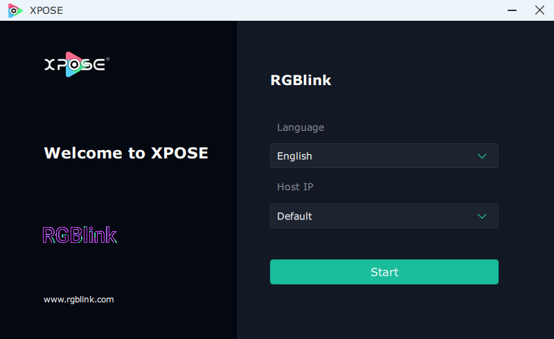
If a device is connected successfully, the main workspace displays the rear panel of the device.
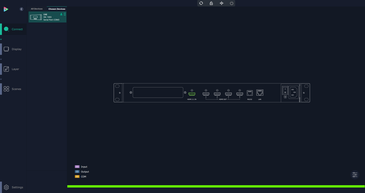
Workspace Overview

The XPOSE 2.0 workspace includes the following functional areas:

  • Workspace
  • System Settings
  • Properties
  • Device Connection
  • Input/Output Configuration
  • Display Management
  • Layer Configuration
  • Scene Management

The toolbar at the top of the workspace provides quick access to the following functions:

  • Synchronize Device
  • Lock Workspace
  • Center Rear Panel
  • Power On/Off

Use the mouse wheel to zoom in or out of the workspace.

Toolbar at the Top

System Settings

Click the ⚙ Settings icon in the lower-left corner to open the System Settings page.
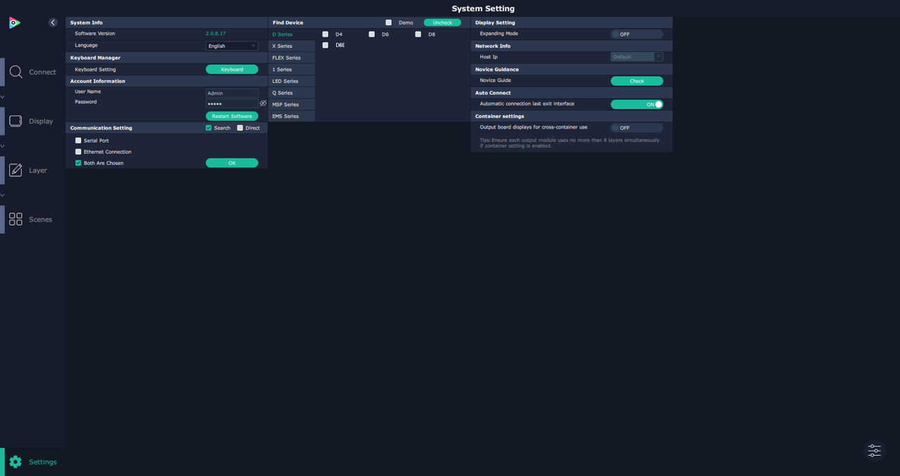
System Settings Page

The following settings are available.

System Info

Displays the current software version and language.

Keyboard Manager

Configure keyboard shortcuts for inputs, outputs, layers, and scenes.

Drag frequently used functions onto the corresponding keys. Shortcut configurations can also be exported or imported.
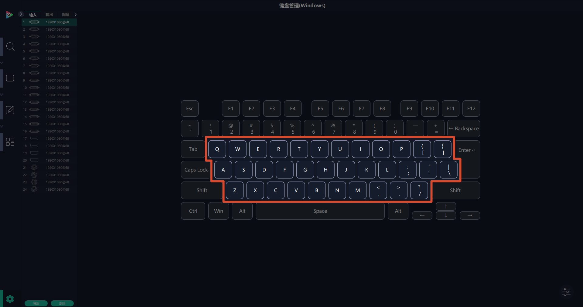
Account Information

Displays the current username and password.

You can also restart XPOSE from this page.

Communication Settings

Select the communication method used to connect the device.

Supported options include:

  • Serial Port
  • Ethernet Connection
  • Both are Chosen

Click OK to apply the changes.

Find Device

Select the product series and device model used for device discovery.

Display Settings

Configure the extended display mode.

Network Info

Displays the Host IP address.

Novice Guidance

Checks the XPOSE operation guide.

Auto Connect

When enabled, XPOSE automatically restores the previous workspace the next time the software starts.

Container Settings

Allows displays connected to the same output card to be shared across different containers.

User Management

Properties

Click the properties icon in the lower-right corner (as shown in the red circle) of the main workspace to open the device properties.

The properties page provides access to device information, IP settings, factory reset and so on.
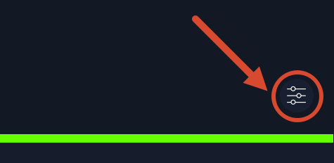
The Properties Icon in the lower-right corner

Permission Management

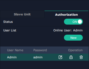
On the System Settings page, click the properties icon to open Authorization.

Authorization allows you to create and edit user accounts, passwords, and operation permissions.

To modify user accounts, first enable Status.
Administrator Login

The first time you perform operations such as firmware upgrade or factory reset, XPOSE requires administrator authentication.

The default administrator account is:

  • Username: Admin
  • Password: admin
User Login

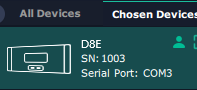
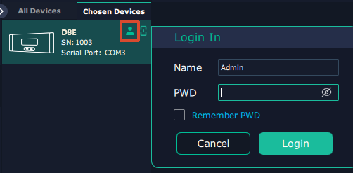
If user accounts have already been created, click the user icon under Main Workspace > Connect > Chosen Devices.

Enter the username and password, then click Log in.

The user icon turns green after a successful login.
User Icon

Adding a User

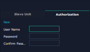
Click New, enter the username and password, then click Save to create the account.
Device Connection
📢  Important

Before searching for devices, select the correct device model and communication method under System Settings > Find Device and Communication Setting.

Click Connect > Search Device.

XPOSE searches for available devices through the selected communication interface.

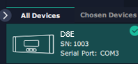
After the search is complete:

  1. Select the target device from All Devices.
  2. Move it to Chosen Devices.

The device is now ready for configuration.
👉

Input and Output Configuration

Input and Output Configuration

The rear panel of D8 is displayed in the workspace. Each input and output port can be configured independently. The selected port is highlighted with a red animated border.
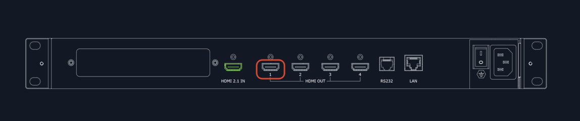
Highlighted Port

Input Configuration

Select the input port to configure, then click the properties icon to view input properties and configure EDID.

Input Properties

The following input properties can be viewed. Modification is currently not supported.

  • Input Port: The currently selected port and input type.
  • Scaling and Cropping
  • Color Space
  • Bit Depth
EDID Configuration

The following parameters are available:

  • Input Port: Displays the selected input.
  • Basic Parameters: Configure the custom width, height, and refresh rate.
Output Configuration

Select the output port to configure, then click the properties icon.

The following output settings are available:

  • Output Resolution
  • DE Parameters
Output Resolution

The HDMI 2.0 output module Format Type supports both Standard Mode and Customize.

  • Select Standard Mode to choose a resolution from the drop-down list.
  • Select Customize to define the width, height, and refresh rate.
DE Parameters

The following parameters can be configured:

  • Output Port
  • Bits: 8-bit (default), 10-bit, or 12-bit
  • HDR: SDR (default), HDR10, or HLG

Display Management

Display Management is used to create Containers and configure display layouts.

Click Display to open the Display Management page.

D8 uses the Cross layout by default. To use a different layout, press and hold × in the upper-right corner of the current Container to delete it, then create a new Container.

Creating a Container

A Container defines the layout of the output displays. In XPOSE 2.0, a Container represents a complete display system, such as an LED display or an LCD video wall.

Click the properties icon, then configure the following:

  • Chose container mode
  • Chose container resolution
  • Chose auto create monitor
  • Chose container row and col

After the configuration is complete, drag the selected Container template into the workspace.
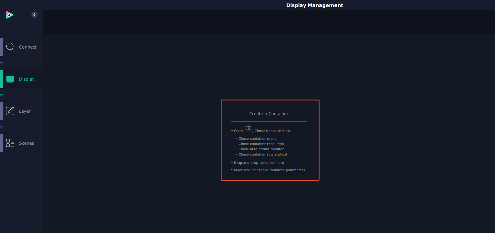
Operation Guidance

Configuring Displays

After creating a Container, you can adjust the display layout and position.

Click the properties icon to configure the Template, Output, and Display System.

Template

XPOSE 2.0 supports multiple display modes simultaneously. Each Container is identified by a different border color.

D8 supports Split mode.

When the output resolution is changed in Split mode, the current Container is removed automatically. A new Container must be created.

Custom Template

Click Template > Customize.

  1. Select the monitor type and AOI layout.
  2. Enter the total width, total height, number of rows, and number of columns. XPOSE calculates the dimensions of each output automatically.
  3. Click Create to create the Container.
  4. Click Save to save the Container as a template.
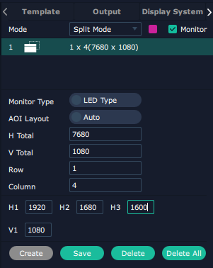
Customize Template Page

Adjusting the Container Layout

The following operations are supported:

  • Move: Drag the Container border to reposition it within the workspace.
  • Zoom: Click - or +, or use the mouse wheel while the pointer is inside the Container.
  • Delete: Press and hold × in the upper-right corner of the Container.
Output

The Output panel lists all output ports.

  • Active ports are available.
  • Gray ports are unavailable or already assigned.

To assign an output, drag the desired output port onto a display in the Container.

To replace an assigned output, drag another output port onto the target display. The original output becomes available again.
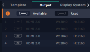
Output Page

Display System

The Display System panel lists all created Containers.

Click the Edit icon (🖋) to rename a Container.
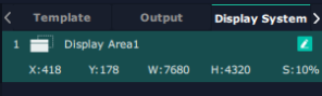
Display System Page

Layer Configuration

Layer Configuration is used to manage layers on each output.

Click Layer to open the Layer Configuration page.

The left panel displays the available Display Area, Layer, and Signal.

Display Area

Displays all Containers created in Display System.

Select a Container to display it in the workspace.
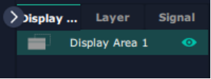
Signal

Displays all available input signals.

Drag a signal from the list onto the desired display within a Container.

By default, each signal is identified by its input resolution.

To rename a signal, click the Edit icon (🖋), enter a new name, then click √.
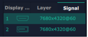
Layers

After a signal is assigned to a display, the Layers panel lists the corresponding layer number and signal.

The toolbar provides the following operations:

  • Bring to Front
  • Move Forward
  • Move Backward
  • Select All
  • Copy
  • Paste
  • Delete

Toolbar

Available Layers

The number displayed on each output indicates the remaining available layers.

As signals are added, the available layer count decreases. When no layers remain, additional signals cannot be assigned.
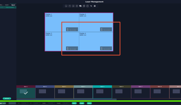
📢  Notes

D8 supports one 8K layer.

Editing Layers

Select a layer, then click the properties icon.

The following settings are available:

  • Scale
  • Crop
  • Tags
  • Hotkey
Scaling and Cropping

Layers can be adjusted using either of the following methods.

Method 1

Select the layer and enter the X Position, Y Position, Width, and Height at the bottom of the workspace.

Click Save to apply the changes.

Method 2

Open the properties icon > Scale, then enter the X Position, Y Position, Width, and Height.

Click the Lock Aspect Ratio icon to maintain the aspect ratio when resizing.
the Lock Aspect Ratio icon

Scene Management

Click Scenes to open the Scene Management page.

Click the button in the lower-left corner to switch between Manual Mode and Schedule Mode.
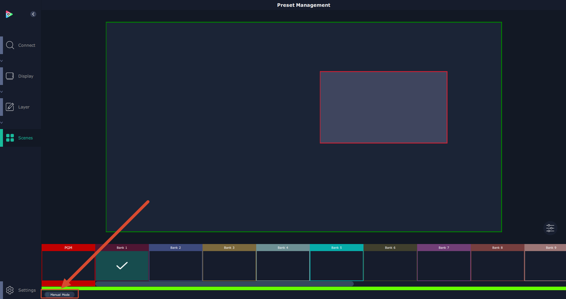
Mode Switch

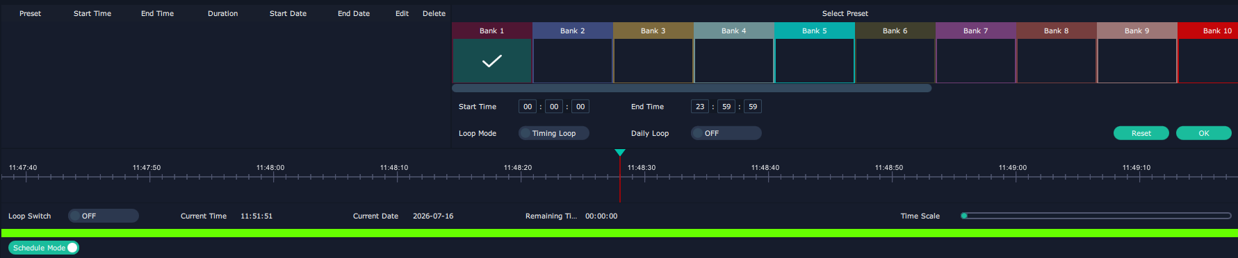
Schedule Mode

Schedule Mode automatically recalls scenes according to a scheduled timetable.

To configure scheduled playback:

  1. Enable Schedule Mode.
  2. Select the Loop Mode.
  3. Select the desired scene Bank.
  4. Set the start and end times.
  5. Click OK.

Schedule Mode

To edit or delete an existing schedule, click the corresponding Edit or Delete icon, then enable the schedule.

Bank List

Manual Mode

Switch to Manual Mode, select a scene, then click the properties icon.

The following options are available:

  • Take Setting
  • Preset Name
  • Hotkey
Take Setting

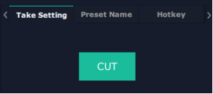
Click CUT to switch from PVW to PGM immediately.
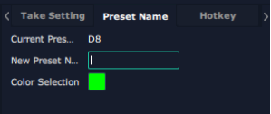
Preset Name

Rename the current scene and assign a scene label color.
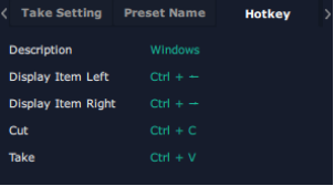
Hotkey

Displays the keyboard shortcuts available for scene switching.
22Upgrade

D8 Series support upgrades through XTOOL.
Visit the RGBlink official website for instructions on installing and using XTOOL.

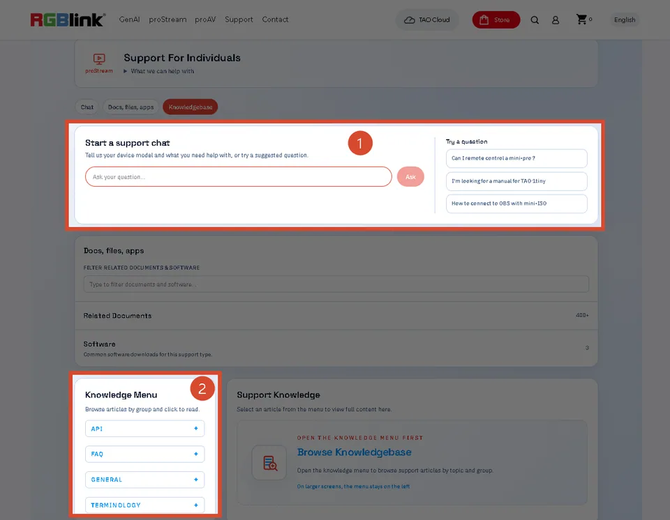
Article Link

Navigation Path

Visit the RGBlink official website and navigate to Support > proAV/proEvents > Knowledge Menu > GENERAL > XTOOL.

This menu group contains XTOOL software installation and operation.

23Technical Support

24Revision History

VersionDateDescriptionAuthor
V1.02026-08-24First ReleaseAlyn

About Us / Find Support

Xiamen RGBlink Science & Technology Co., Ltd. designs and manufactures professional video processing, switching, streaming and LED display control products for live events, broadcast, education and fixed installations.

Need help?

Choose one of the following support options:

  • AI Support Search (Recommended): Visit Support > Support proStream/proAV/proEvents on the RGBlink official website and ask the RGBlink AI Bot for quick answers.
  • FAQs: Visit Support > Support proStream/proAV/proEvents on the RGBlink official website and browse Knowledge Menu > FAQ.
  • Contact Technical Support: Visit the Technical Support page of this manual or the RGBlink official website for our contact details.

Document image

RGBlink

www.rgblink.com

© Copyright Xiamen RGBlink Science & Technology Co Ltd