Export PDF

RGBlink
mini-extreme ISO

User Manual

mini-extreme ISO

mini-extreme ISO User Manual

230-0014-01-0

RGBlink

www.rgblink.com

November 2026

1mini-extreme ISO - Specifications

Document image
mini-extreme ISO: Industry-First 8-Channel 4K Audio-Video Production Switcher
Key Features + 5.5-inch touchscreen for icon menu control, preview, and working status display + 8 video input chanels ( 4 x HDMI 2.0, 2 x 12G-SDl, UVC and NDI) + Maximum 11 channels for audio mixing + 1-CH HDMI 2.0 program output and 1-CH HDMI 1.3 for preview + Cut mode and preview transition mode support + USB 3.0 4K60 recording capability, bitrate up to 32Mbps + UVC recording which is USB and UAC devices compatible (including AI mini ) + RTMP/NDI streaming via Ethernet port, managed by TAO Cloud + USB 3.0 UVC 4K outputs via third-party platforms like OBS + Independent control of PTZ, zoom, and focus of multiple PTZ cameras + Chroma key support (green and blue) and Luma key support + Third-party control and integration via free RGBlink Central Control Protocol
Application
Dimension

Connectors

ItemDescription
InputHDMI 2.04 ร— HDMI-A
UVC (4K Webcam)1 ร— USB-C
12G SDI4 ร— BNC (choose 2)
NDI1 ร— RJ45
OutputHDMI 1.3 (Multiview)1 ร— HDMI-A
HDMI 2.0 (Program)1 ร— HDMI-A
USB (4K Record)1 ร— USB-C (H.264)
UVC (4K )1 ร— USB-C
NDI1 ร— NDI
AudioMIC IN 11 ร— 6.35mm XLR + TS Jack (48V Phantom Power)
MIC IN 21 ร— 6.35mm XLR + TS Jack
LINE IN1 ร— 6.35mm TRS Jack
OUT1 ร— 6.35mm TRS Jack
1 ร— 3.5mm mini-Jack
Communication/UpgradeHTTPS Web UI1 ร— RJ45
PowerPower Supply1 ร— USB-C

Performance

ItemDescription
Input ResolutionHDMI 2.0
SMPTE720p@50/60; 1080p@30/50/60; 2160p@30/50/60
VESA1024 ร— 768p@60; 1280 ร— 720p@60; 1280 ร— 768p@60; 1280 ร— 800p@60; 1280 ร— 1024p@60; 1360 ร— 768p@60
1366 ร— 768p@60; 1440 ร— 900p@60; 1600 ร— 1200p@60; 1680 ร— 1050p@60; 1920 ร— 1080p@60
1920 ร— 1200p@60; 3840 ร— 2160p@60; 4096 ร— 2160p@60
12G-SDI
SMPTE720p@50/59.94/60; 1080p@30/50/60; 2160p@30/50/60
Output ResolutionHDMI 1.3
SMPTE1080p@60
HDMI 2.0/USB (Webcam)
SMPTE1080p@30/50/60; 2160p@30/50/60
VideoVideo FormatsHDMI 2.0; HDCP 2.2
Grayscale/ Video SamplingHDMI 2.0 Input: YUV444; YUV422; RGB (8/10/12bit)
HDMI 2.0 Output: RGB 8bit
USB (Record): YUV420 8bit
Video Latency<4 frames
AudioAudio FormatHDMI: Linear PCM, 24 bits/48 kHz, 2 ch
USB: Linear PCM, 16 bits/48 kHz, 2 ch
Record/StorageRecord FormatsMP4; H.264/MPEG-4 AVC
Disk FormatsFAT32(โ‰ค32 GB); exFAT(64GB~2T)
Supported StandardsHDMI2.0
USB3.0
NDINDI, HX3
๐Ÿ“ข Notes
NDI|HX3 supports resolutions up to 4K@30.
- 1 Channel: 4K@30/25 NDI|HX3, backward compatible with NDI|HX and NDI|HX2.
- 2 Channels: 2K@60/50/30/25 NDI|HX3, backward compatible with NDI|HX and NDI|HX2.

Power

ItemDescription
CompatabilityUSB Power Delivery (PD) 3.0
Supported CablesCertified USB PD Aware
Input PowerUSB-C 20V/3A
Recommended Adapter65W PD Adapter

Working Environment

ItemDescription
Temperature0โ„ƒ~45โ„ƒ
Humidity10%~85% RH

Physical

ItemDescription
WeightNet Weight1.48kg
Packaged Weight2.80kg
DimensionNet Dimension291.0mm ร— 222.7mm ร— 69.5mm
Packaged Dimension332.0mm ร— 238.5mm ร— 109.0mm

Order Codes

Order CodesItem
230-0014-01-0mini-extreme ISO

2mini-extreme ISO - Quick Start

Welcome to the Quick Start Guide.
Follow the steps in this guide to quickly set up your device and get started.

2.1Product Overview

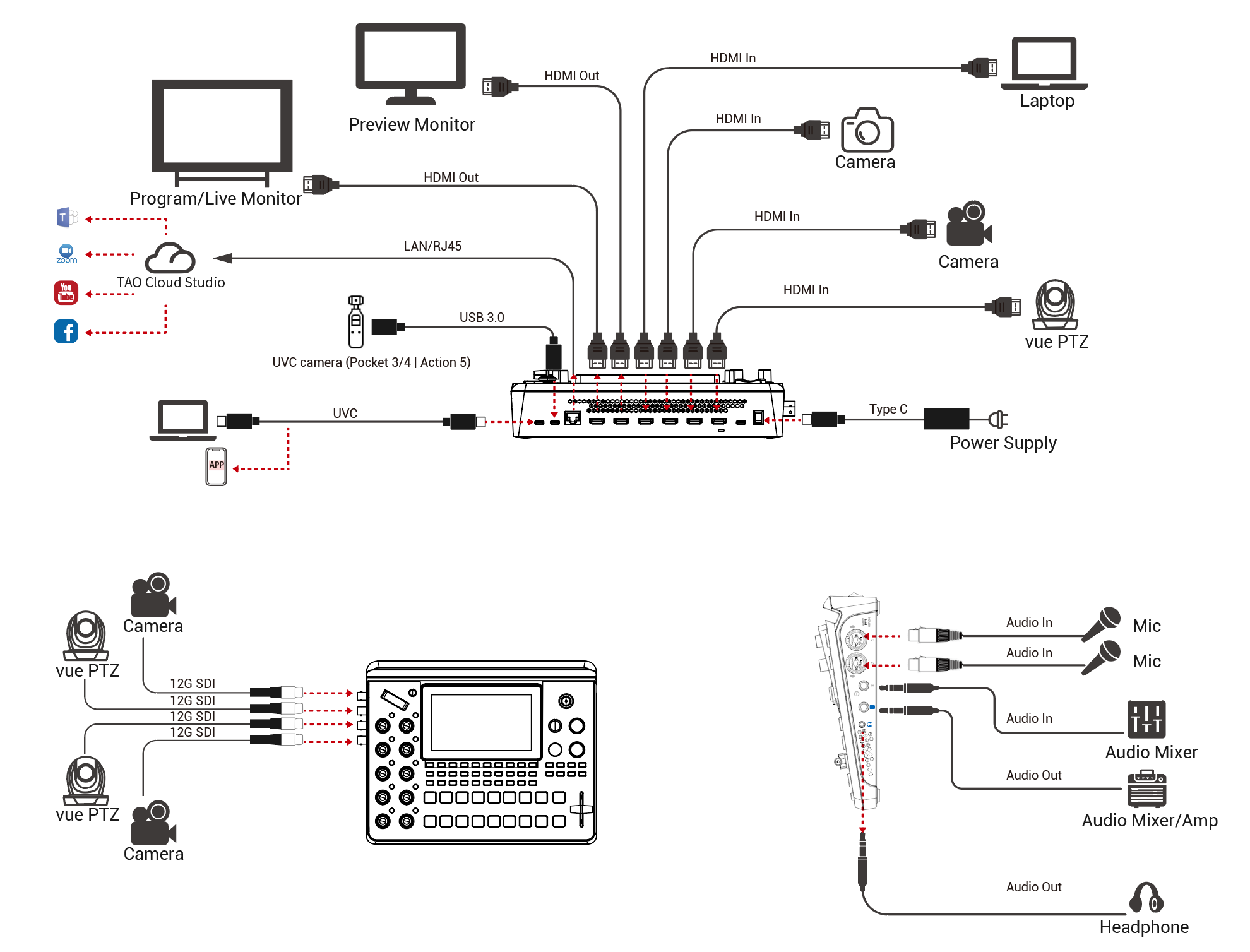
mini-extreme ISO is a professional 4K all-in-one production switcher that integrates video switching, recording, streaming, and multiview monitoring for professional video production and live streaming at events, competitions, conferences, and more.

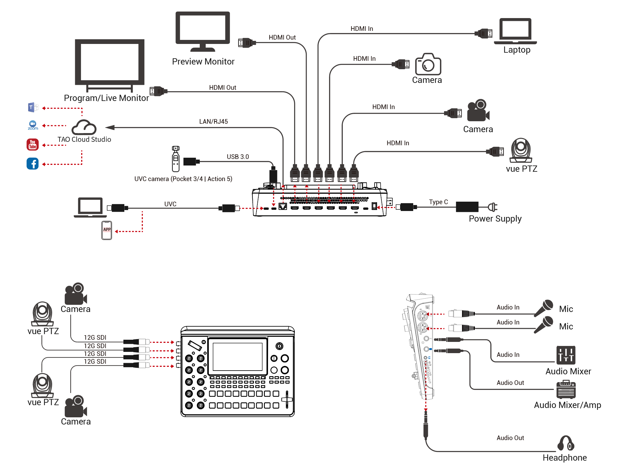
mini-extreme ISO provides 4 HDMI 2.0 inputs and 4 12G-SDI inputs, with up to 2 SDI signals selectable for simultaneous input. It also supports UVC and NDI sources (authorization required).

The 2 HDMI outputs support multiview preview, program output, and test modes.

For audio, mini-extreme ISO supports embedded and analog audio inputs, with 15 channels of independent audio management and up to 11-channel mixed audio output.

The device features 1 USB 3.0 output for driver-free connection to Windows or macOS computers. It is recognized as a webcam and is compatible with mainstream live streaming, video conferencing, and content creation software.

mini-extreme ISO supports RTMP streaming and works with the RGBlink TAO Cloud platform for remote device management and multi-platform streaming distribution.

A 5.5-inch HD touchscreen, combined with front-panel shortcut buttons and controls, provides convenient access to video switching, layer adjustment, PIP, chroma keying, PTZ control, and other common operations. The device can also be accessed and controlled remotely through a WebApp without installing additional software.

In addition to live production, mini-extreme ISO supports ISO recording and scene presets, making it suitable for on-site production, live streaming, recording, and other professional applications.

2.1.1Key Features

Video Processing

  • Supports 4 ร— HDMI, 2 ร— 12G-SDI (2 of 4), UVC, and NDI (authorization required), providing up to 8 video inputs.
  • Supports 1 ร— HDMI 2.0 program output and 1 ร— HDMI 1.3 multiview output.
  • UVC supports USB cameras and UAC devices, such as the AI mini wireless microphone.

Audio Processing

  • Supports 15 audio input channels; Maximum 11 channels for audio mixing.
  • Supports Line In and Mic inputs.
  • Supports mixing of embedded and external audio inputs.
  • Supports advanced audio settings such as noise reduction and equalization.

Recording

  • Supports recording at up to 4K60.
  • Supports simultaneous recording of 1 fixed program output (PGM) and 3 selected input sources.

Common Production Features

  • Supports IP VISCA and NDI protocols for simultaneous control of up to 8 PTZ cameras.
  • Supports chroma keying.
  • Supports picture-in-picture (PiP).
  • Supports multiple transition modes, including cut, effect transitions, and fade to black.

Network and Streaming

  • Supports UVC, NDI, and IP-based video transmission.
  • Supports streaming and NDI output over Ethernet, with streaming transmission managed through TAO Cloud.
  • Supports NDI|HX3, while maintaining compatibility with NDI|HX and NDI|HX2, with resolutions up to 4K60.
  • Connects to a computer via USB-C and is recognized as a webcam for 4K streaming with software such as OBS.

Control and Operation

  • Features a 5.5-inch full-color touchscreen for intuitive touch control.
  • Supports remote access and control through the WebApp.
  • Supports TAO Cloud for remote device management and multi-platform streaming distribution.
  • Supports third-party control and integration through RGBlink's free central control protocol.

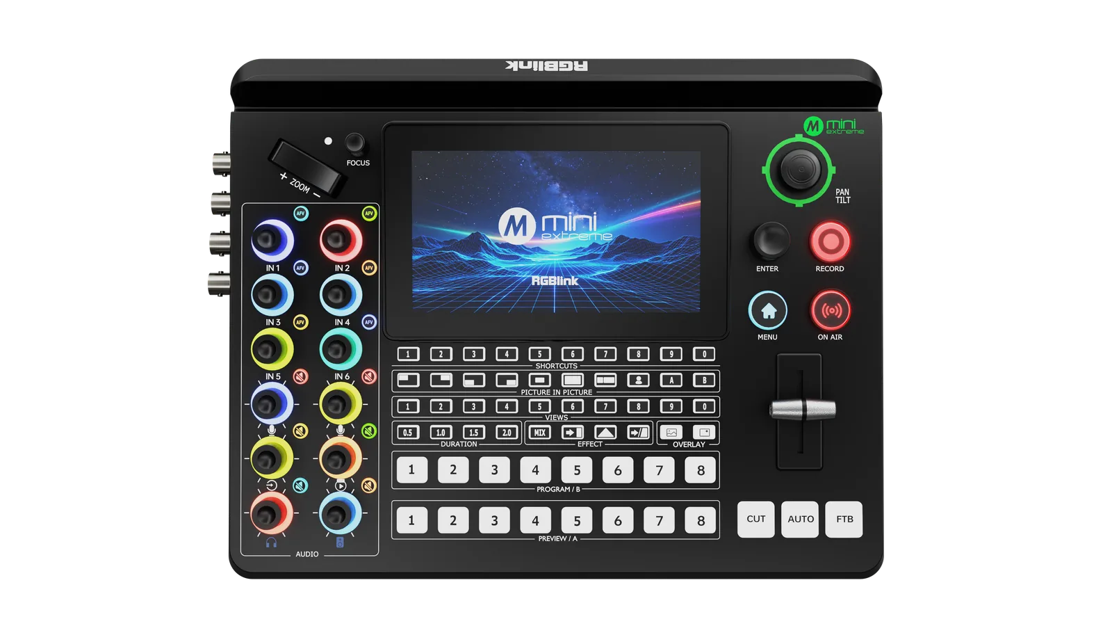
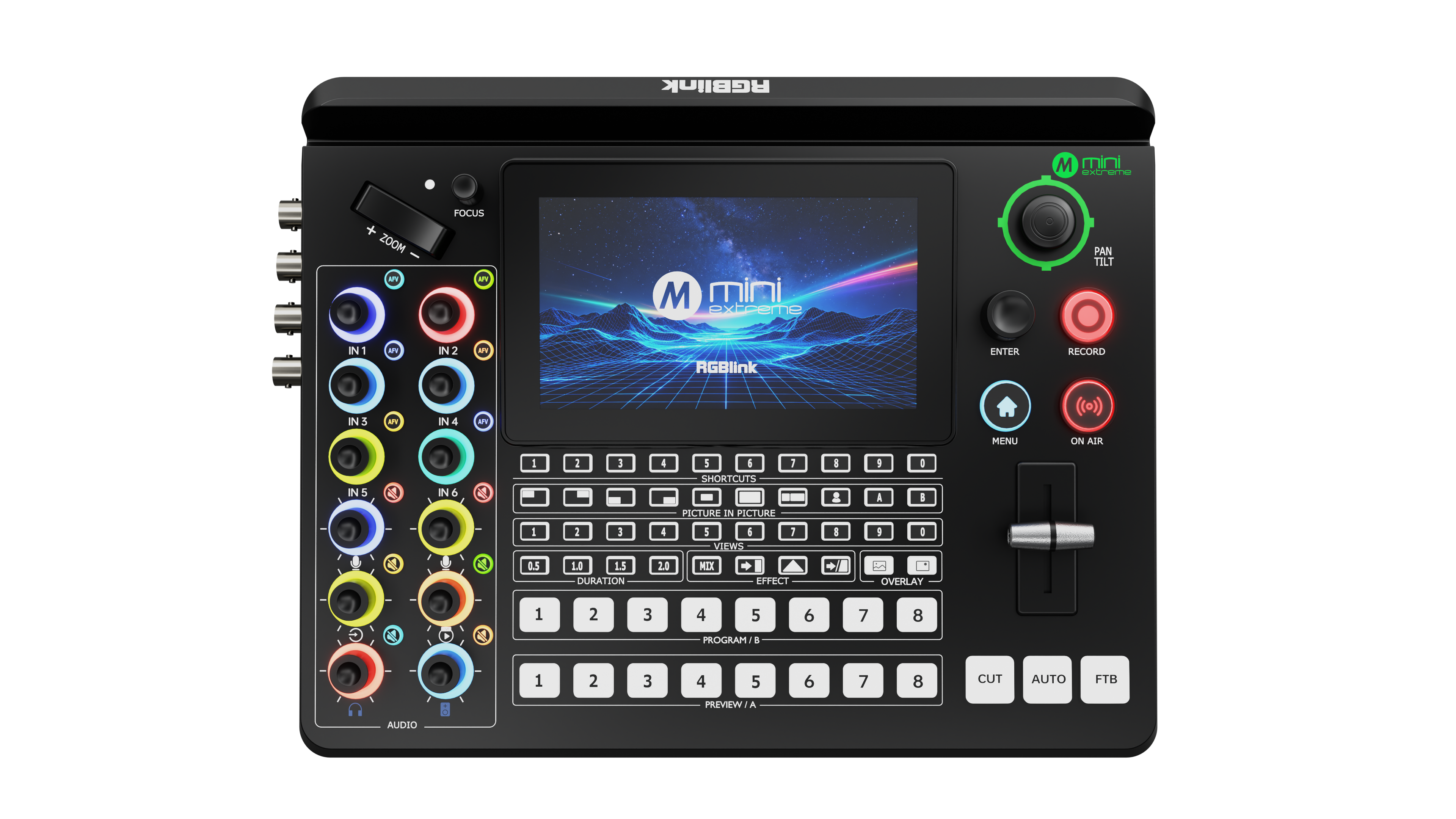
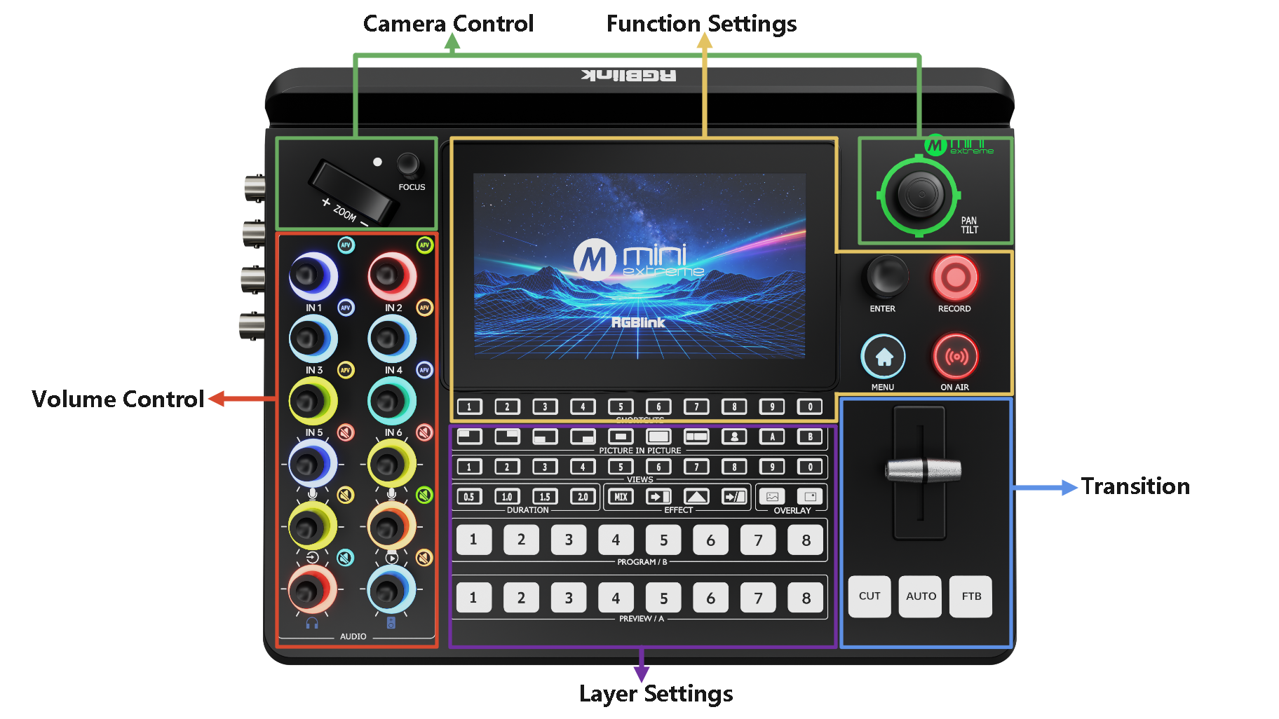
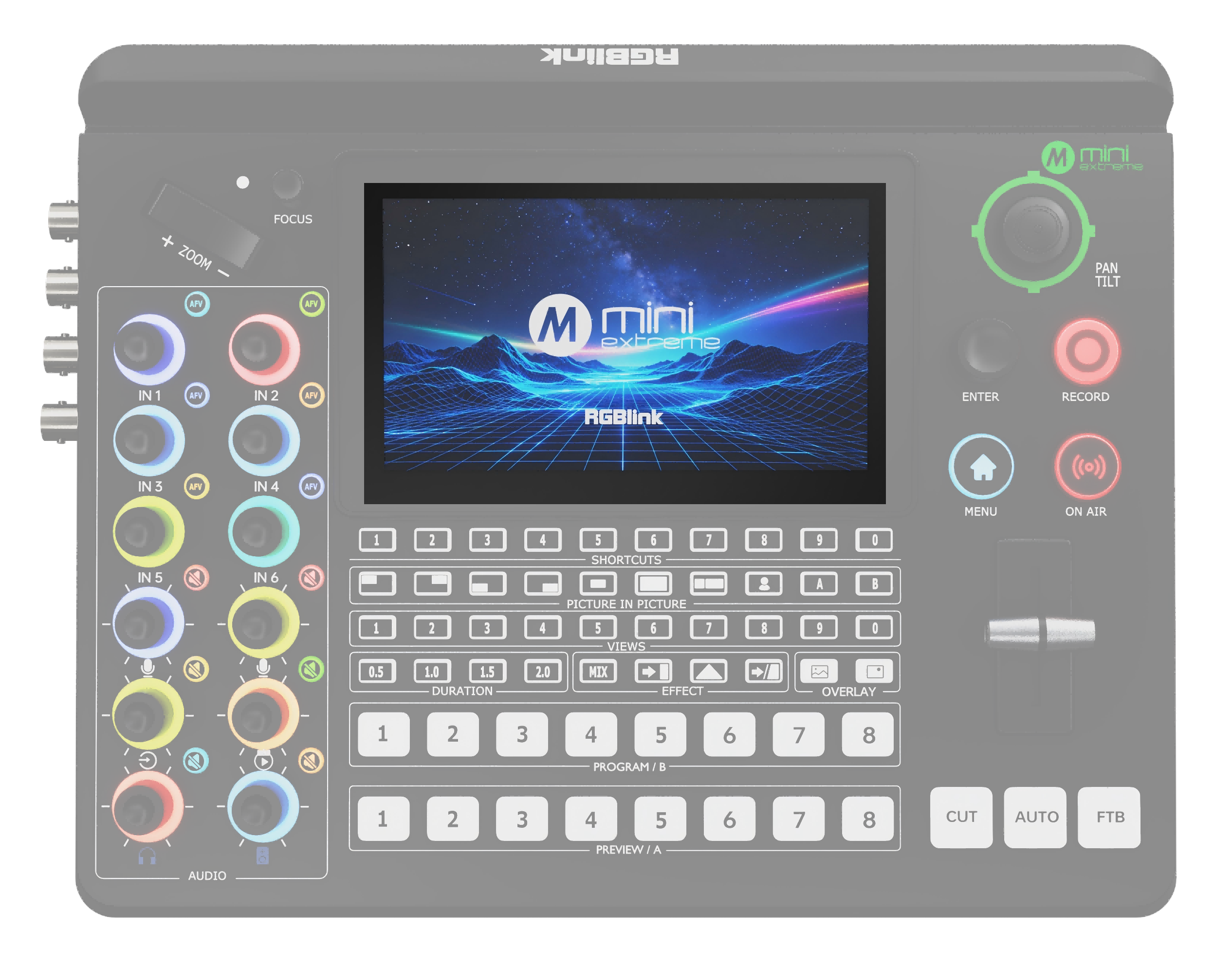
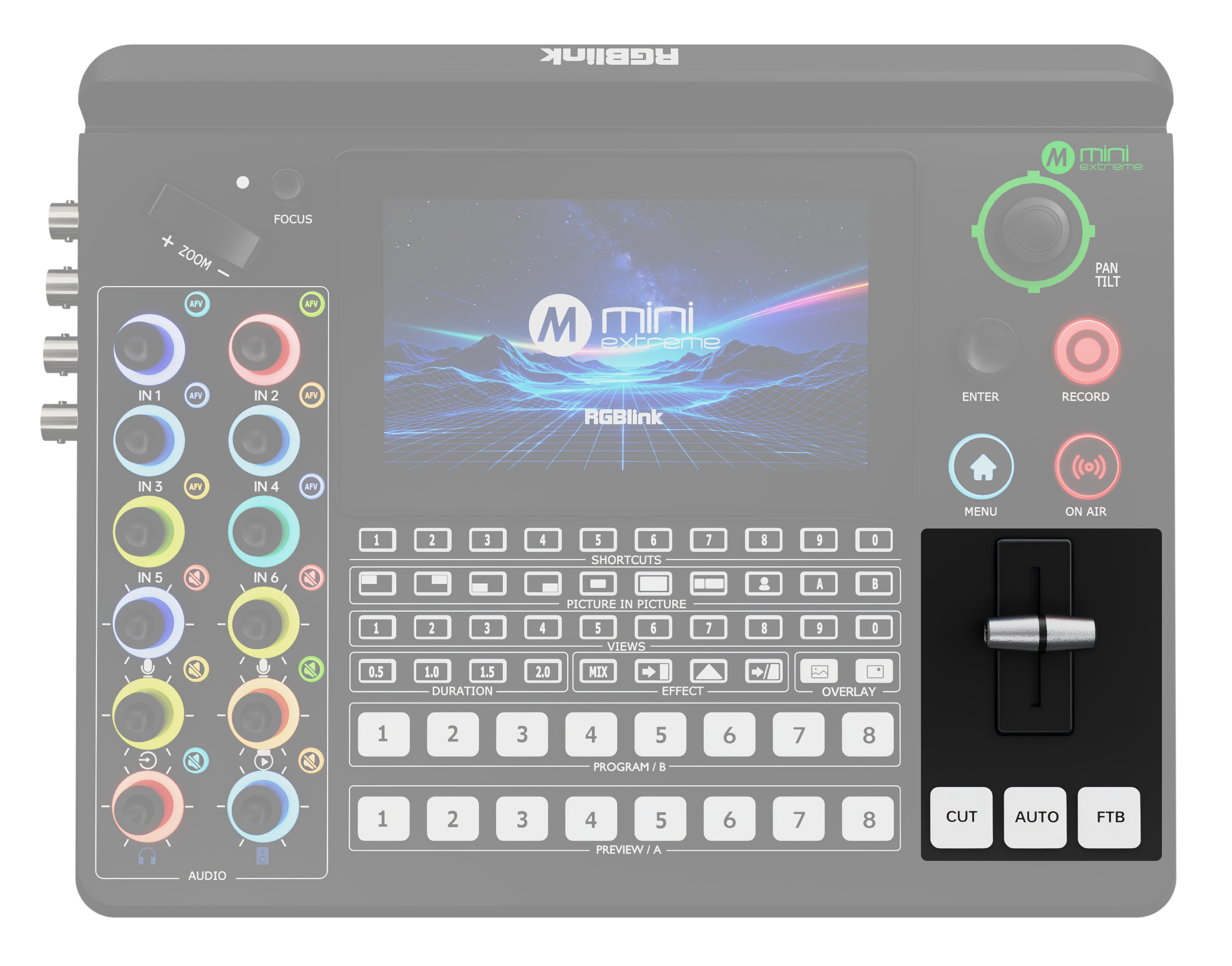
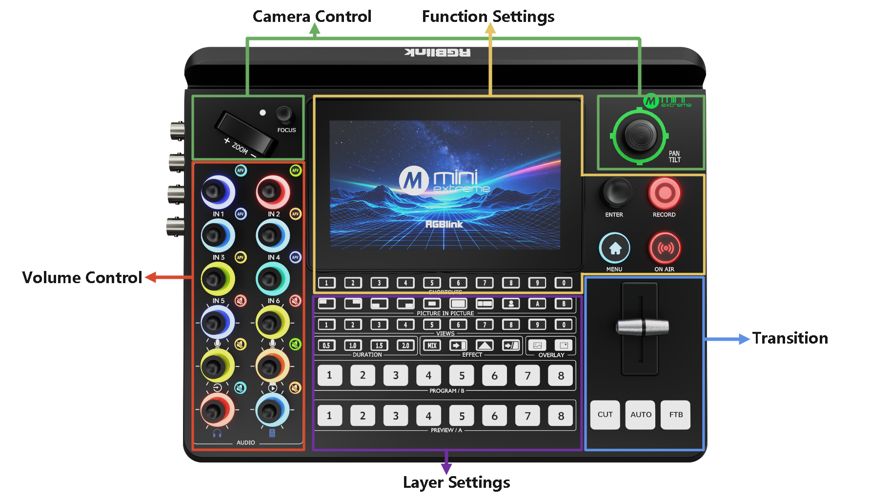
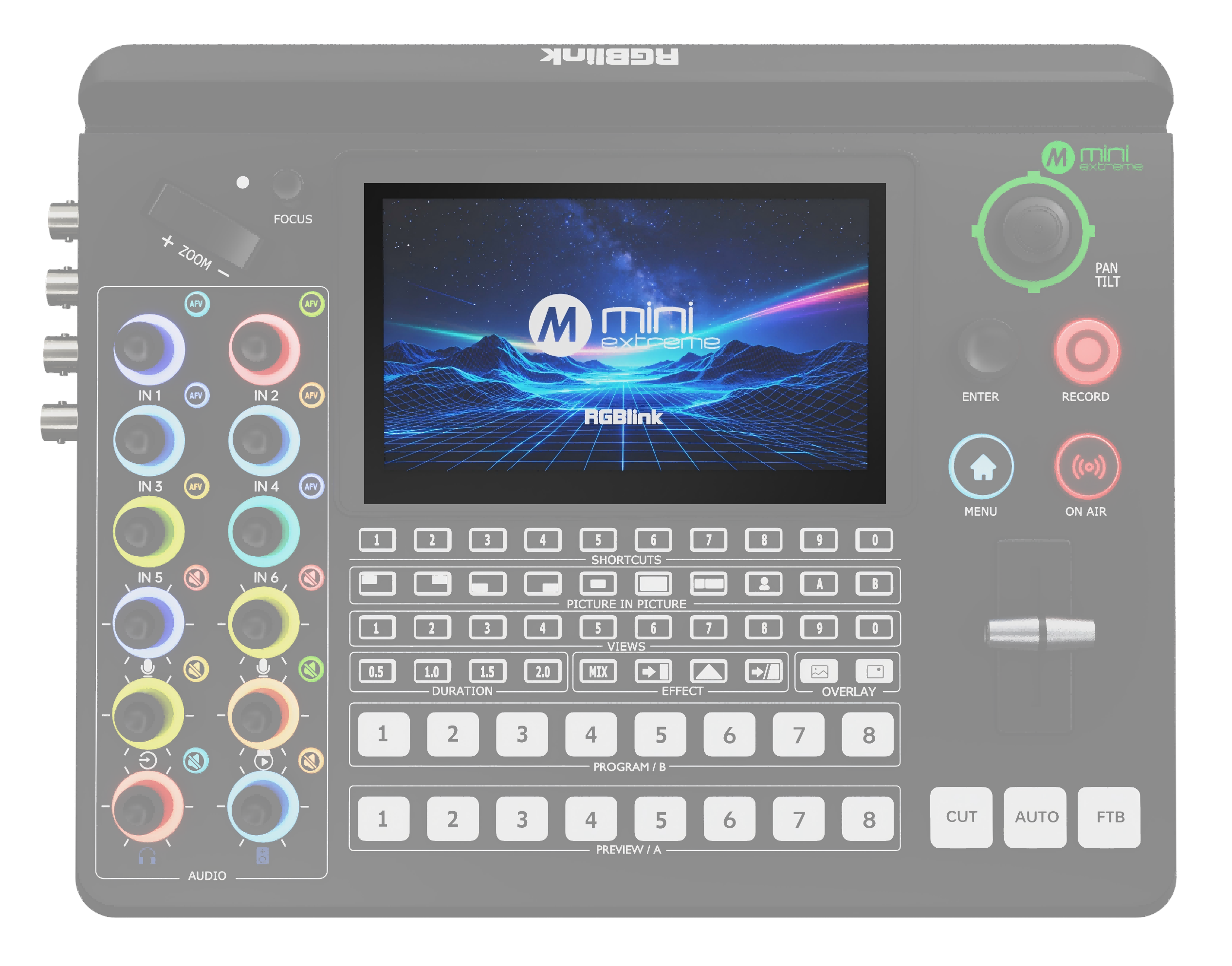
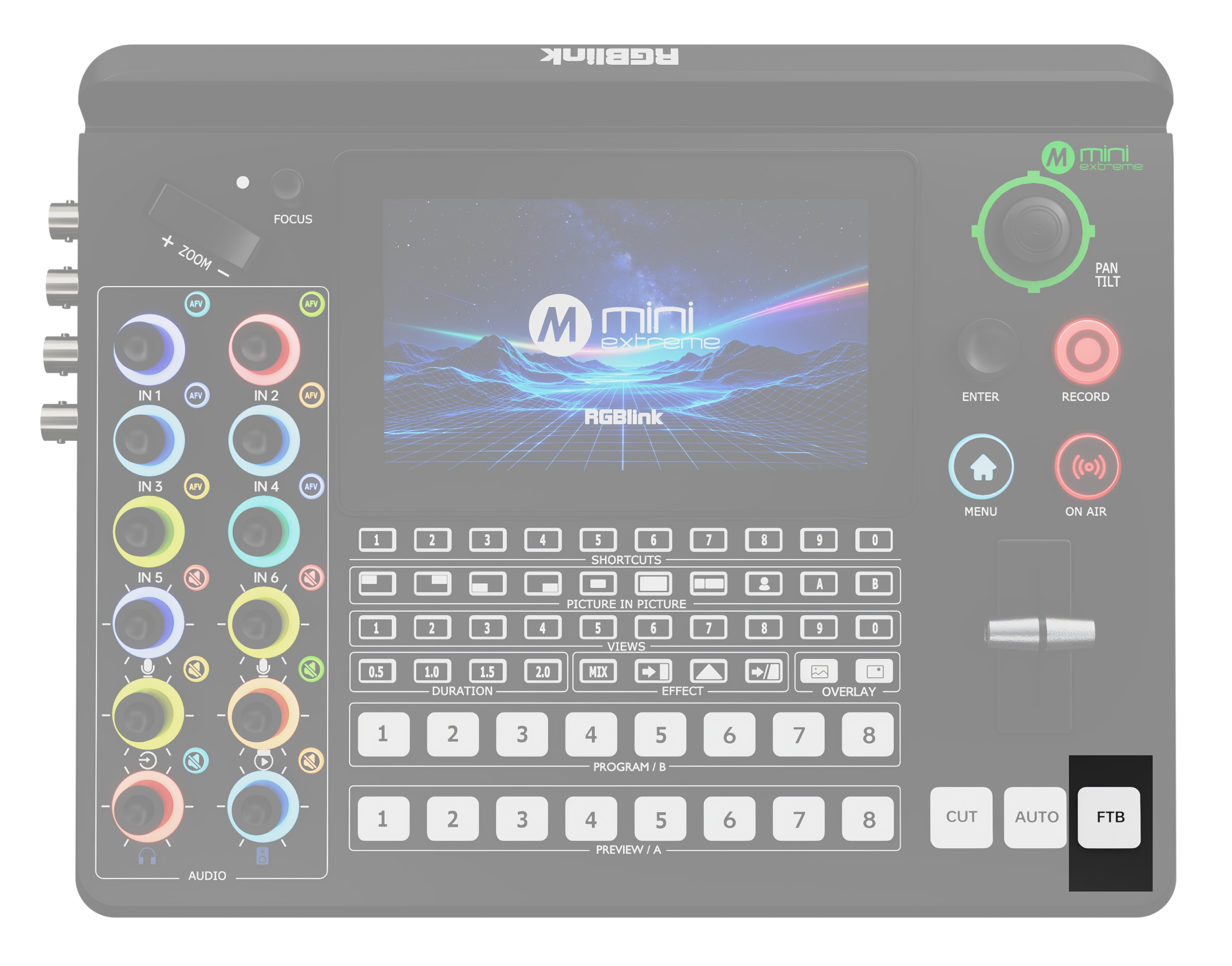
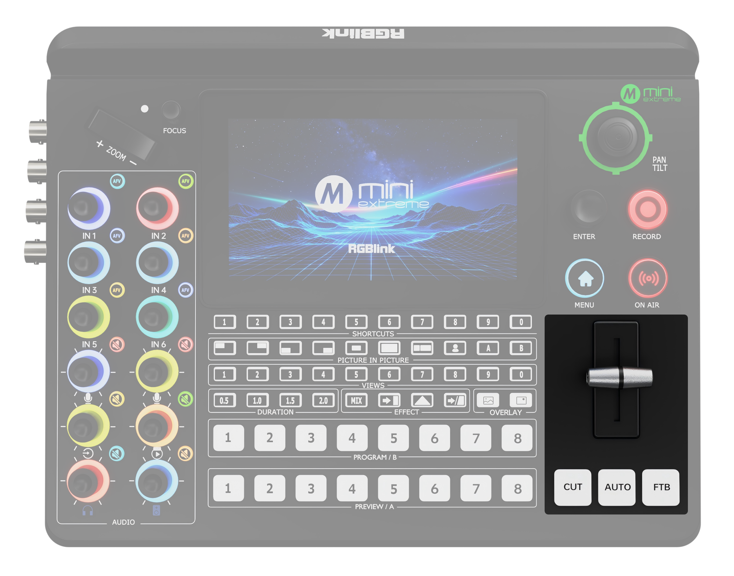
2.1.2Front Panel

AreaDescription
Function Settingsโ—‹ 5.5" HD Touch Screen โ—‹ SHORTCUTS Custom Function Button โ—‹ MENU/EXIT Button โ—‹ ENTER: Menu Browsing/Confirm Button โ—‹ RECORD Button โ—‹ ON AIR Button
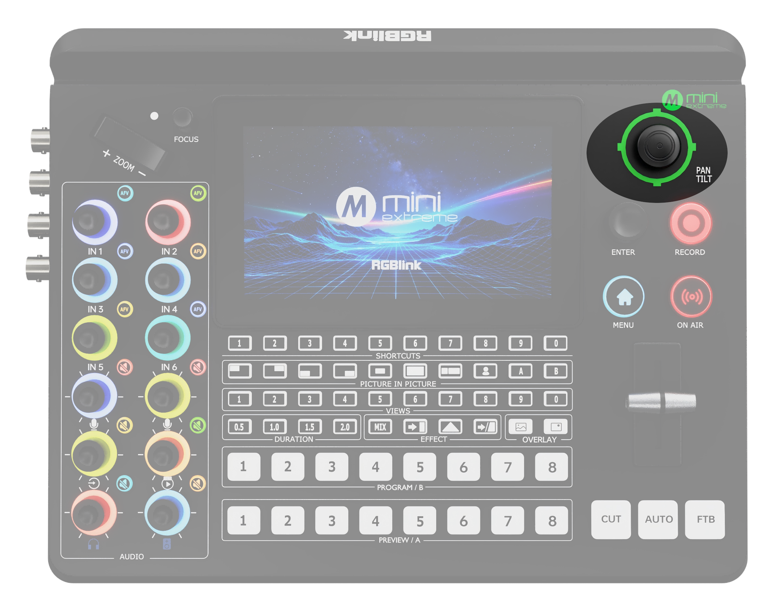
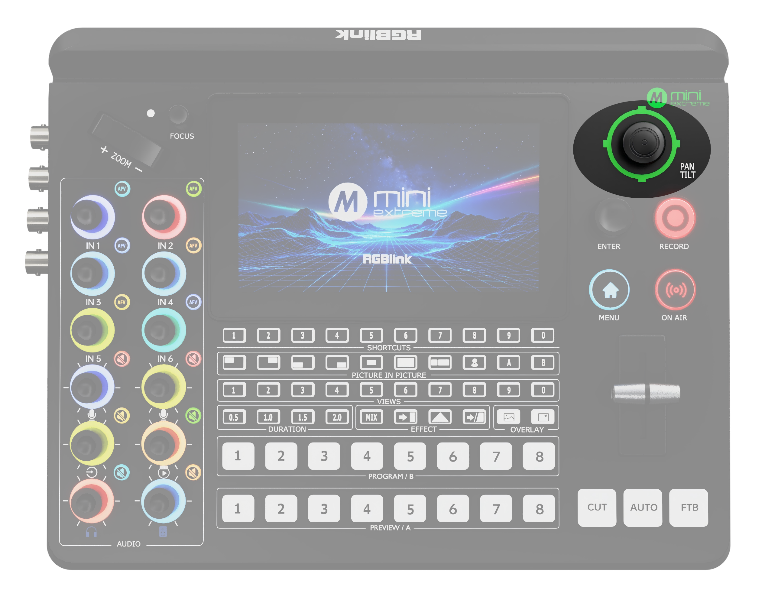
Camera Controlโ—‹ FOCUS knob with indicator โ—‹ ZOOM Toggle โ—‹ 5-Direction Joystick
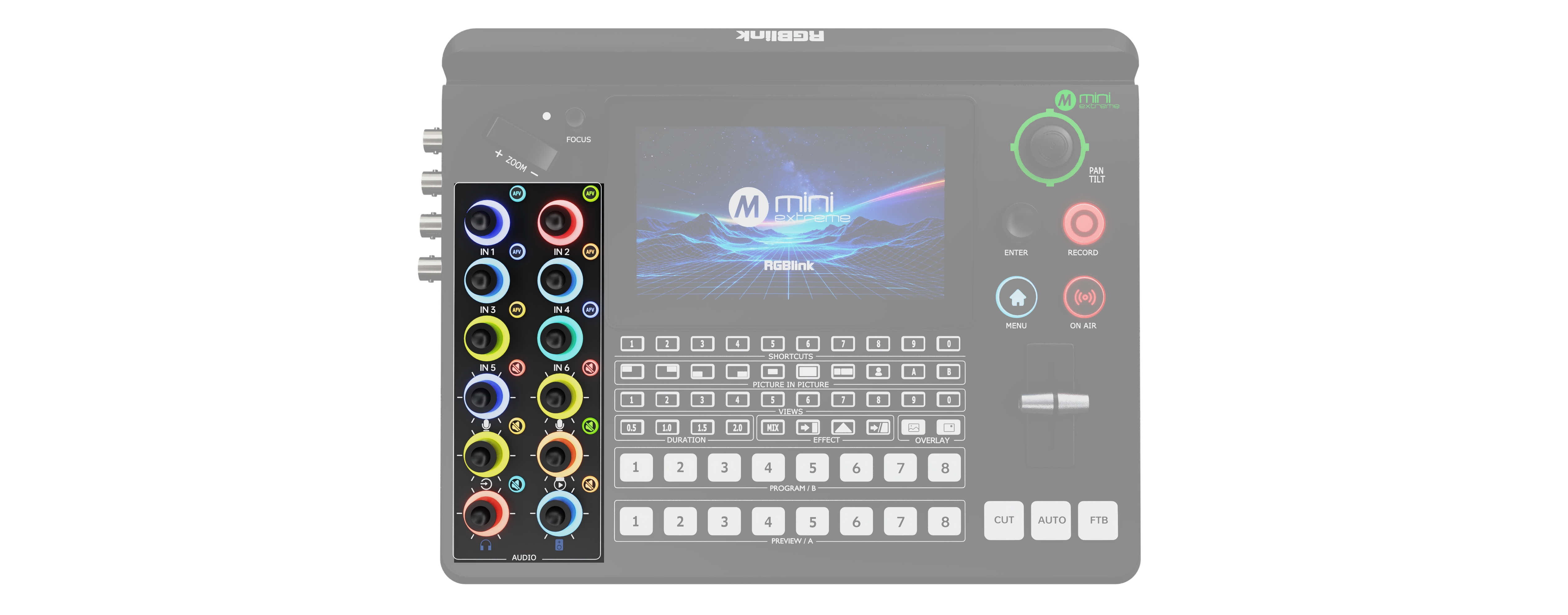
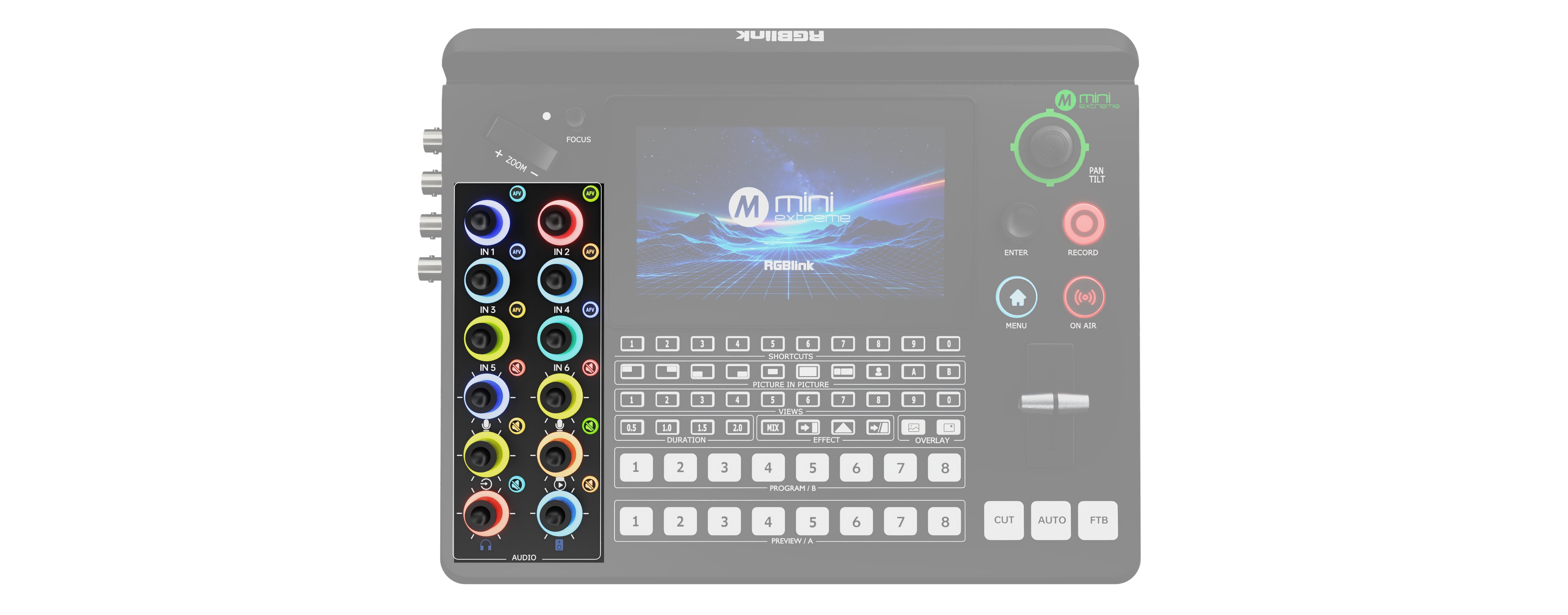
Volume Controlโ—‹ Volume Control Knob โ—‹ AFV (Audio Follow Video) Button โ—‹ Mute Button
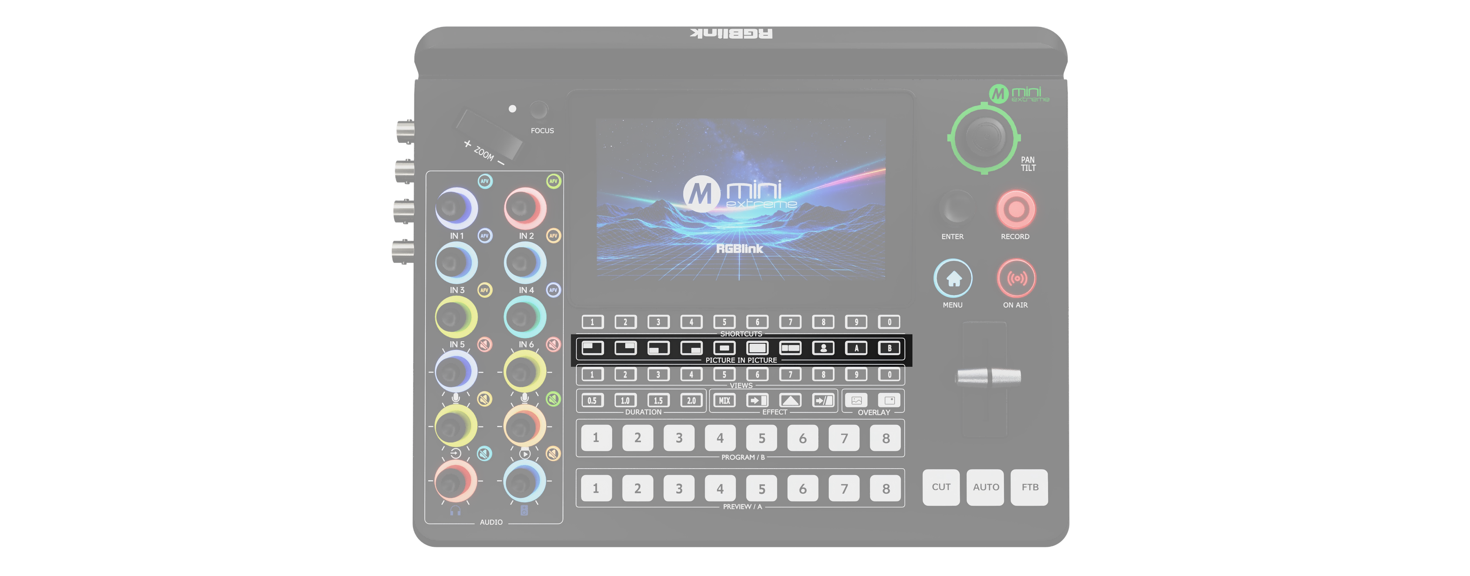
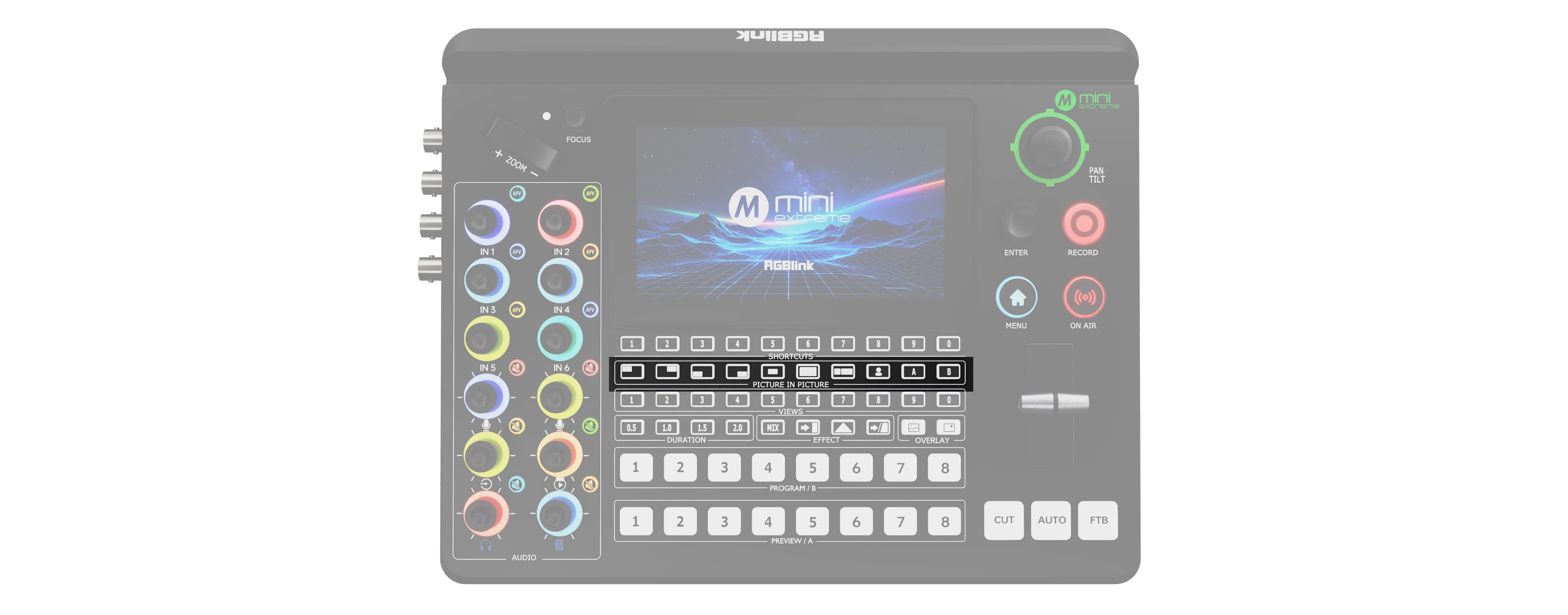
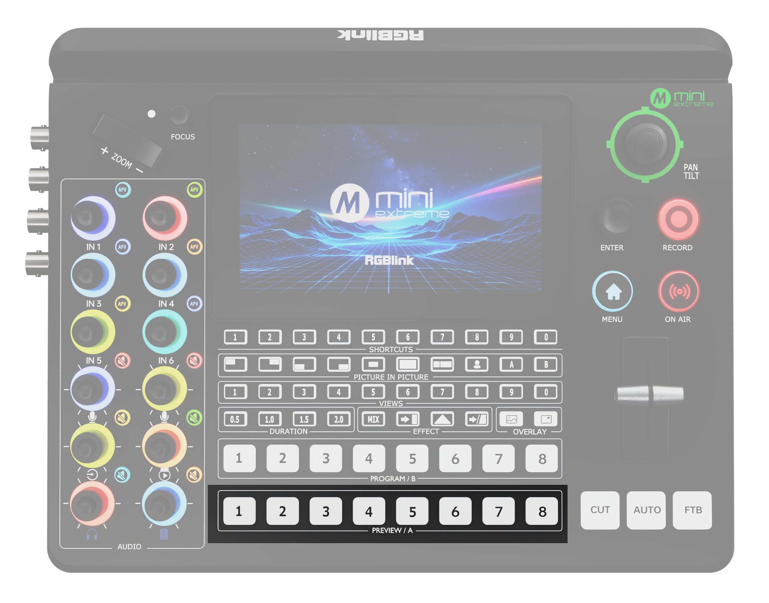
Layer Settingsโ—‹ PICTURE-IN-PICTURE layout selection buttons โ—‹ Chroma Key button โ—‹ A/B Layer selection buttons โ—‹ VIEWS scene recall button โ—‹ EFFECT transition effect selection button โ—‹ DURATION transition duration selection button โ—‹ OVERLAY selection button โ—‹ PROGRAM/B program output and multi-layer preset buttons โ—‹ PREVIEW/A preview output and multi-layer preset buttons
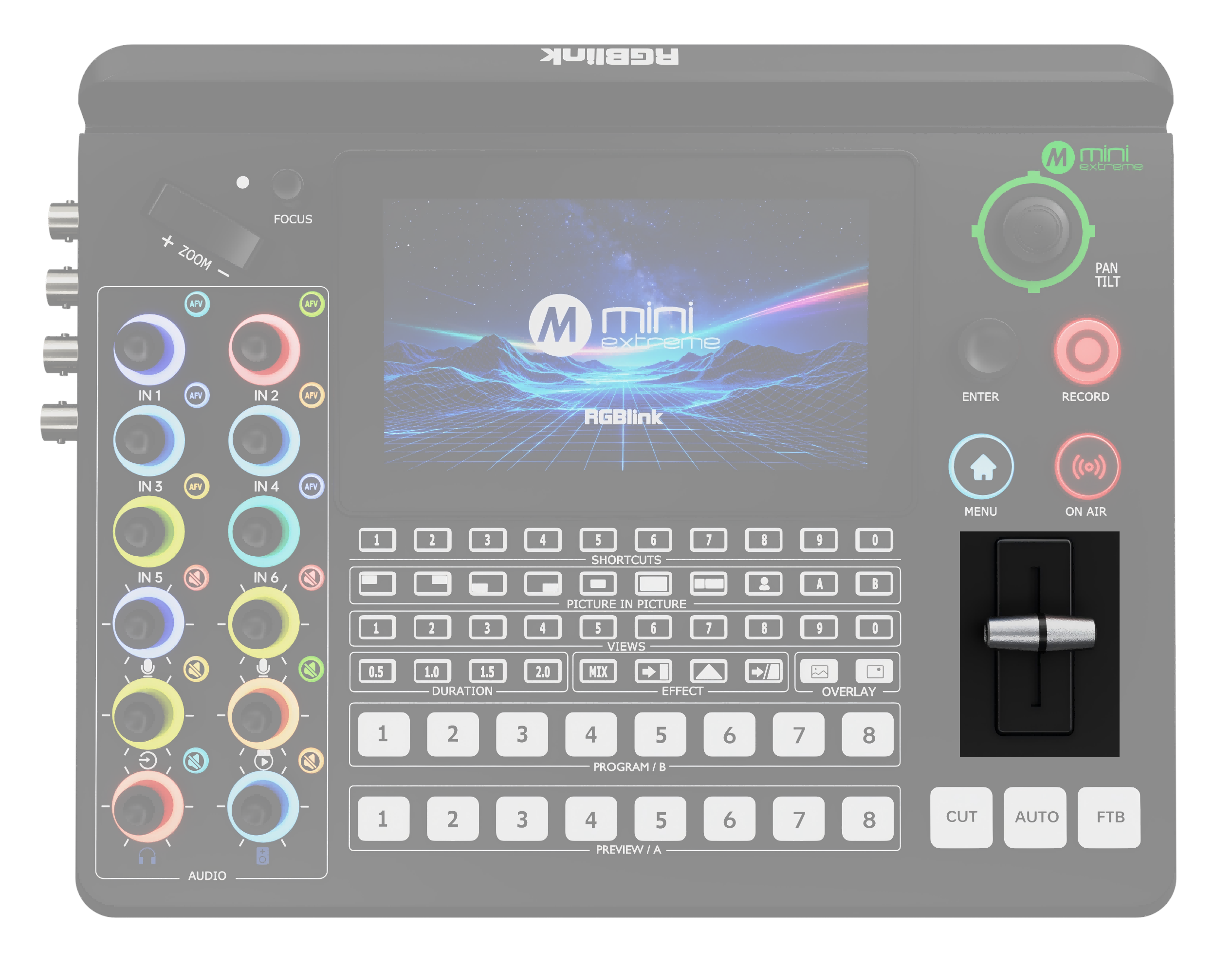
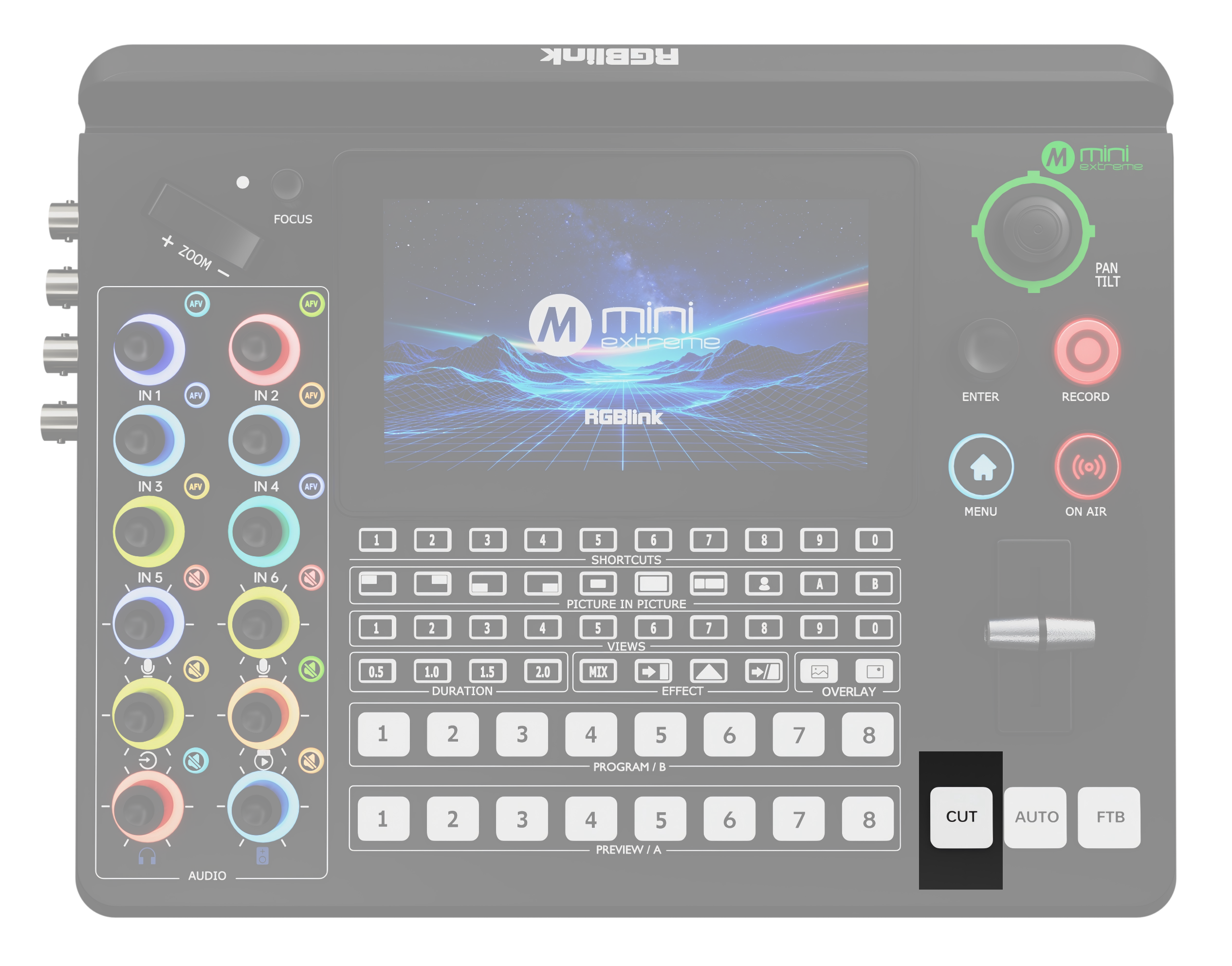
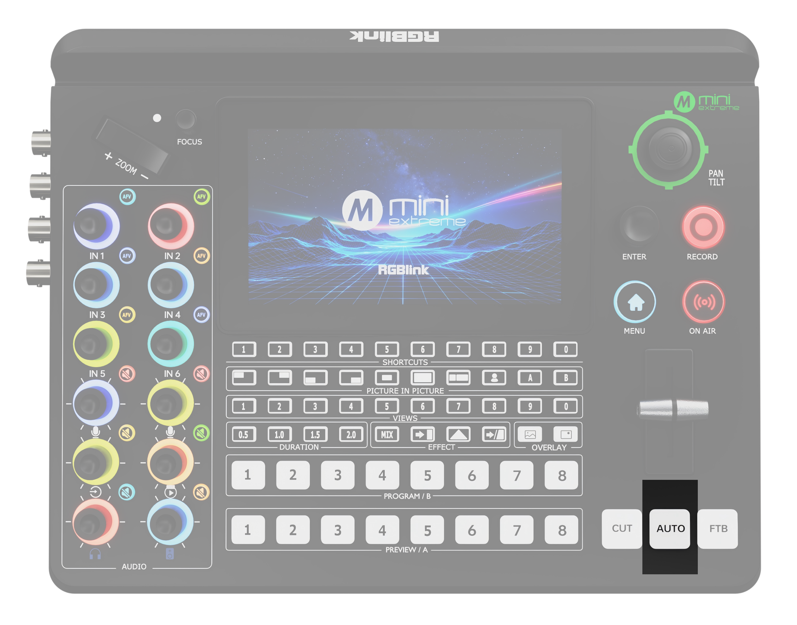
Transitionโ—‹ T-Bar โ—‹ CUT quick transition button โ—‹ AUTO automatic transition button **โ—‹ FTB **fade-to-black transition button

Function Settings

AreaDescription
5.5-inch Full-Color Display Monitors all audio/video inputs and outputs, recording and streaming status, and displays menus.
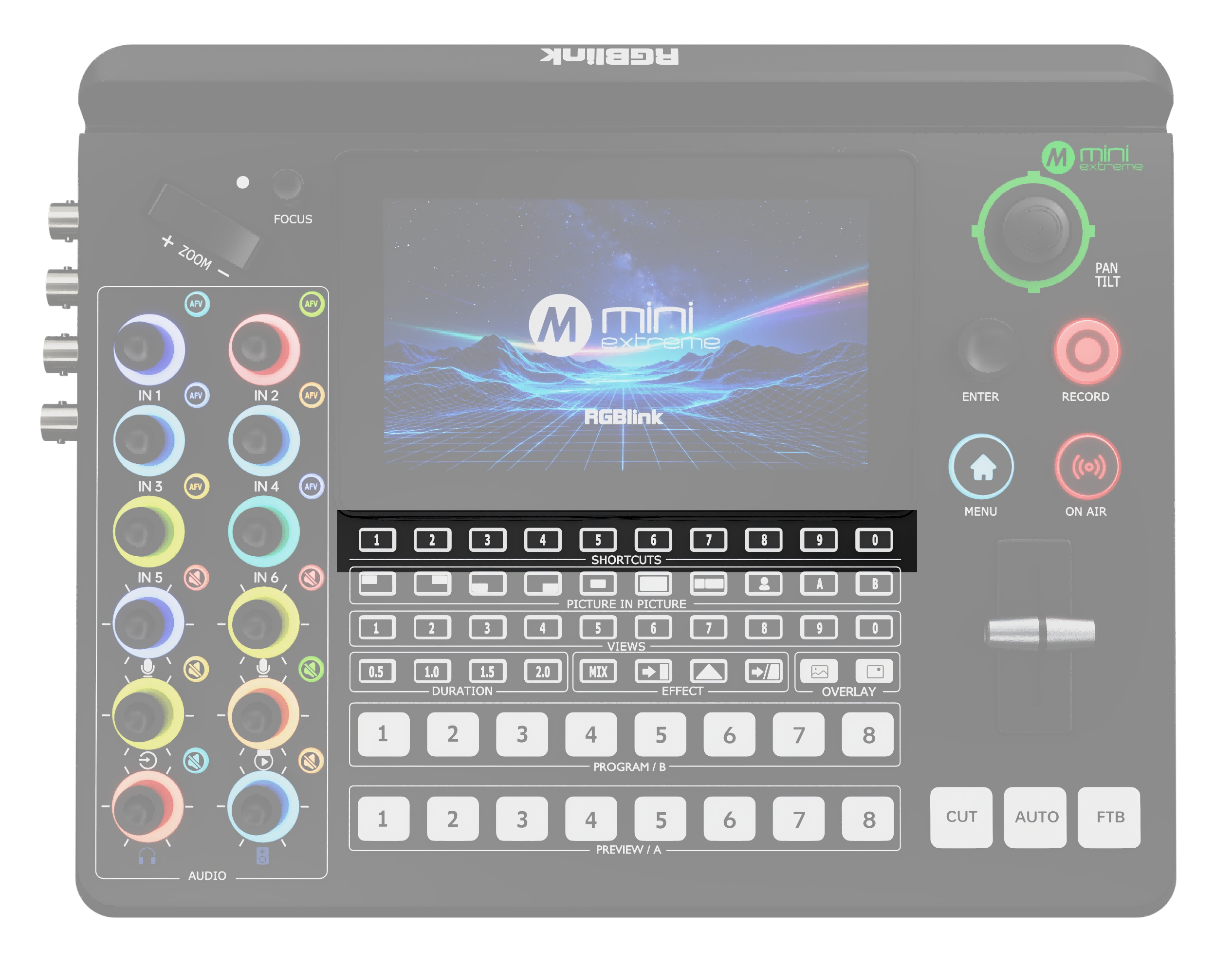
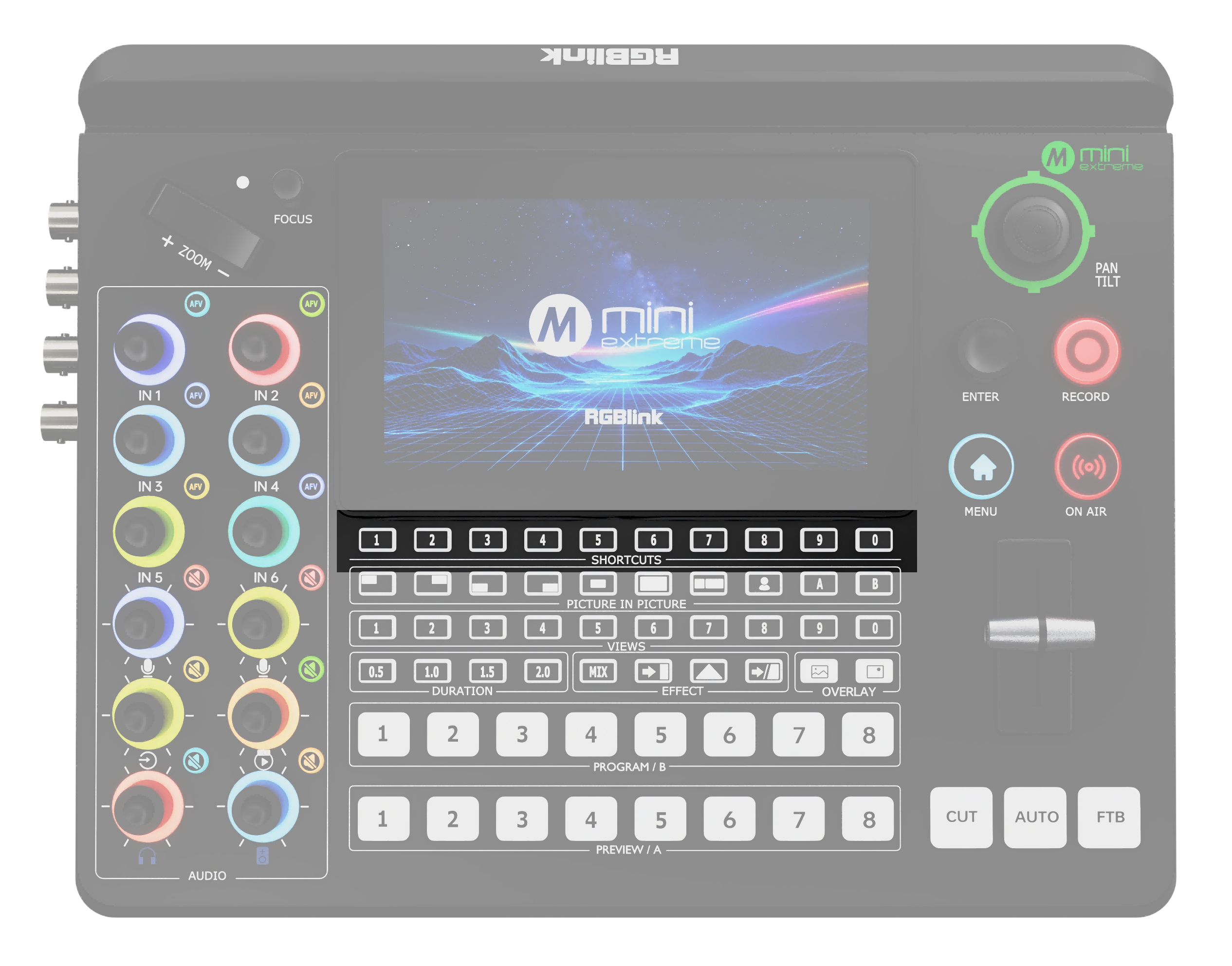
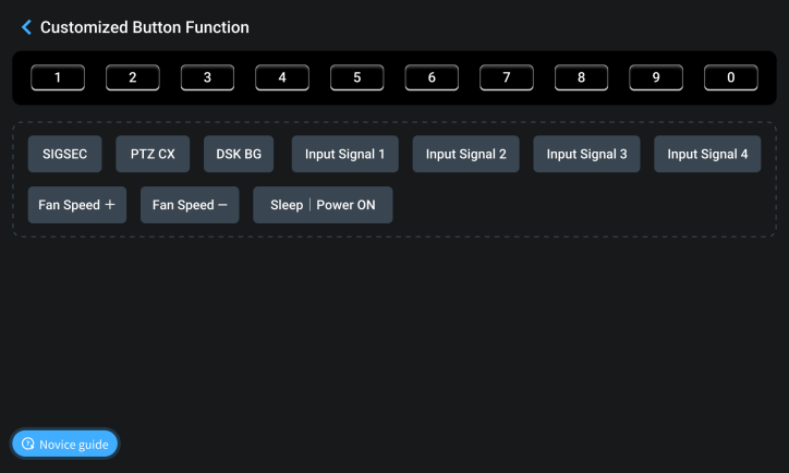
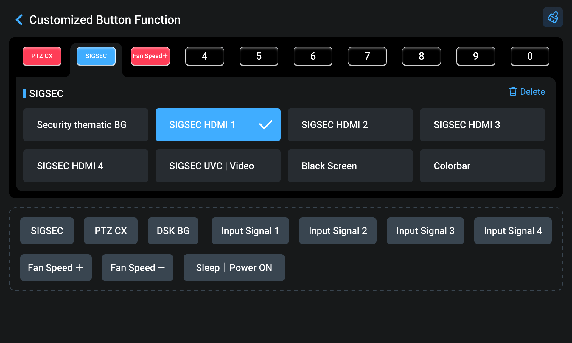
SHORTCUTS (Coming Soon) Button Functions โ—‹ Shortcut functions can be assigned through the Web App. Indicator Status โ—‹ Off: No shortcut function is assigned. โ—‹ Solid white: A shortcut function is assigned. Operation โ—‹ Press: Activates the assigned shortcut function.
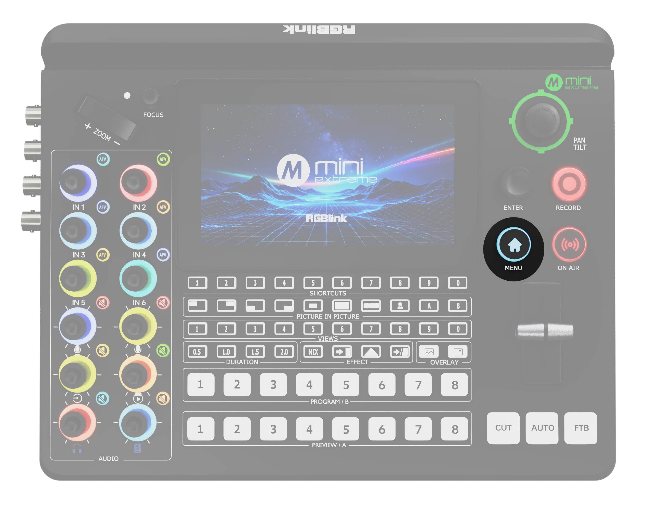
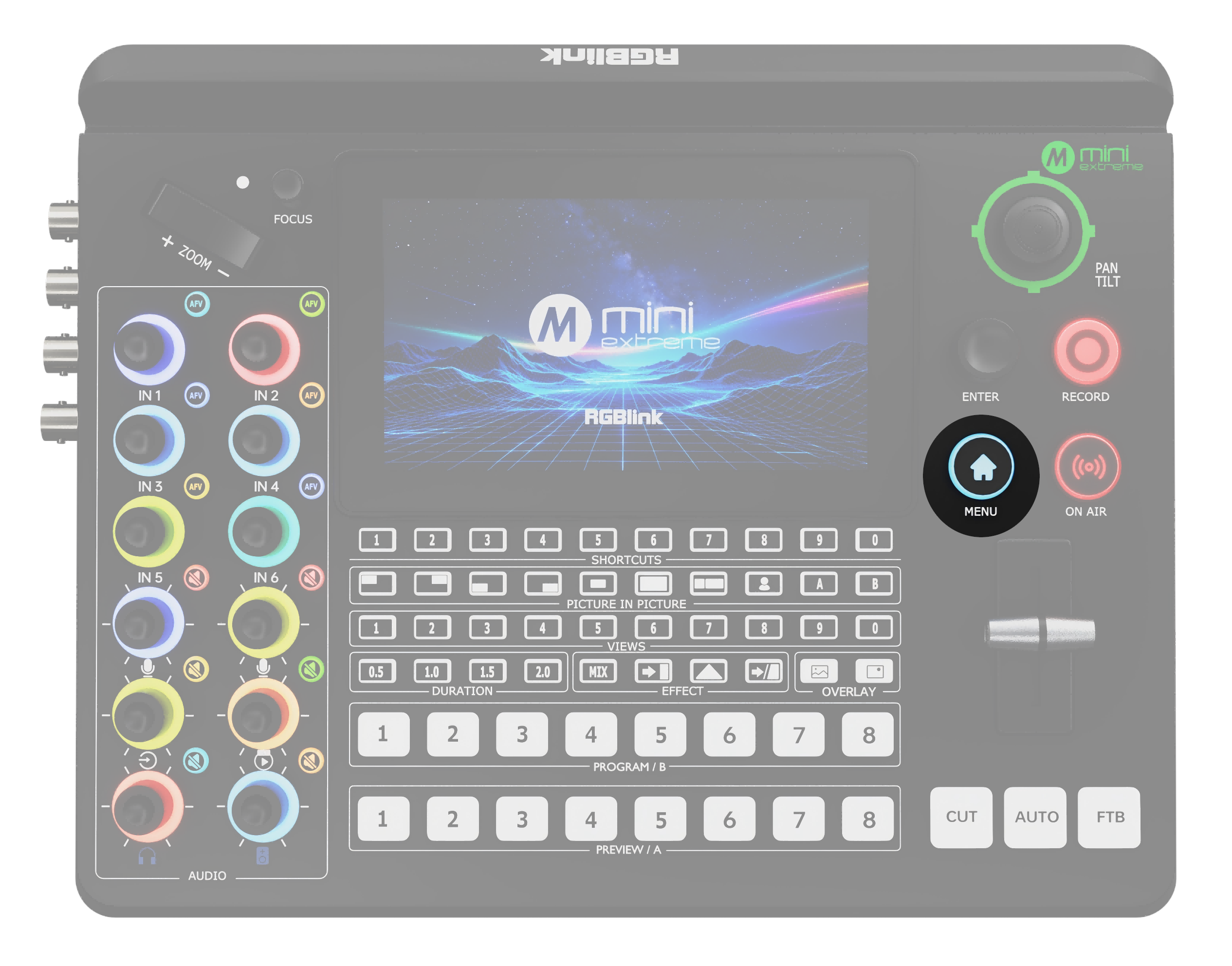
MENU Button Functions โ—‹ MENU: Opens the menu. โ—‹ Back: Returns to the previous screen. โ—‹ Screen Lock: Press and hold for 3 seconds to lock or unlock the screen.
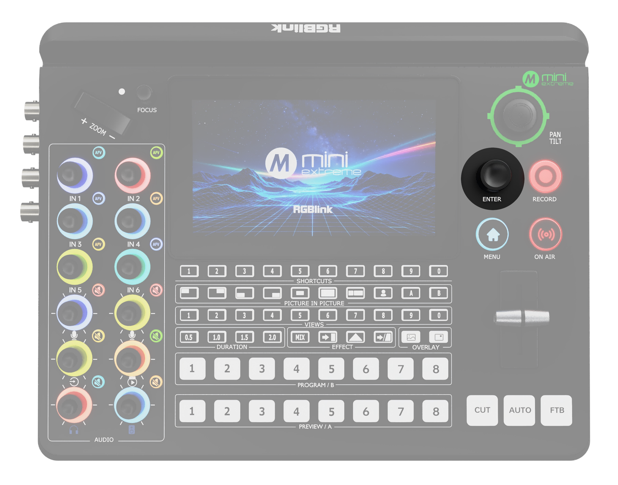
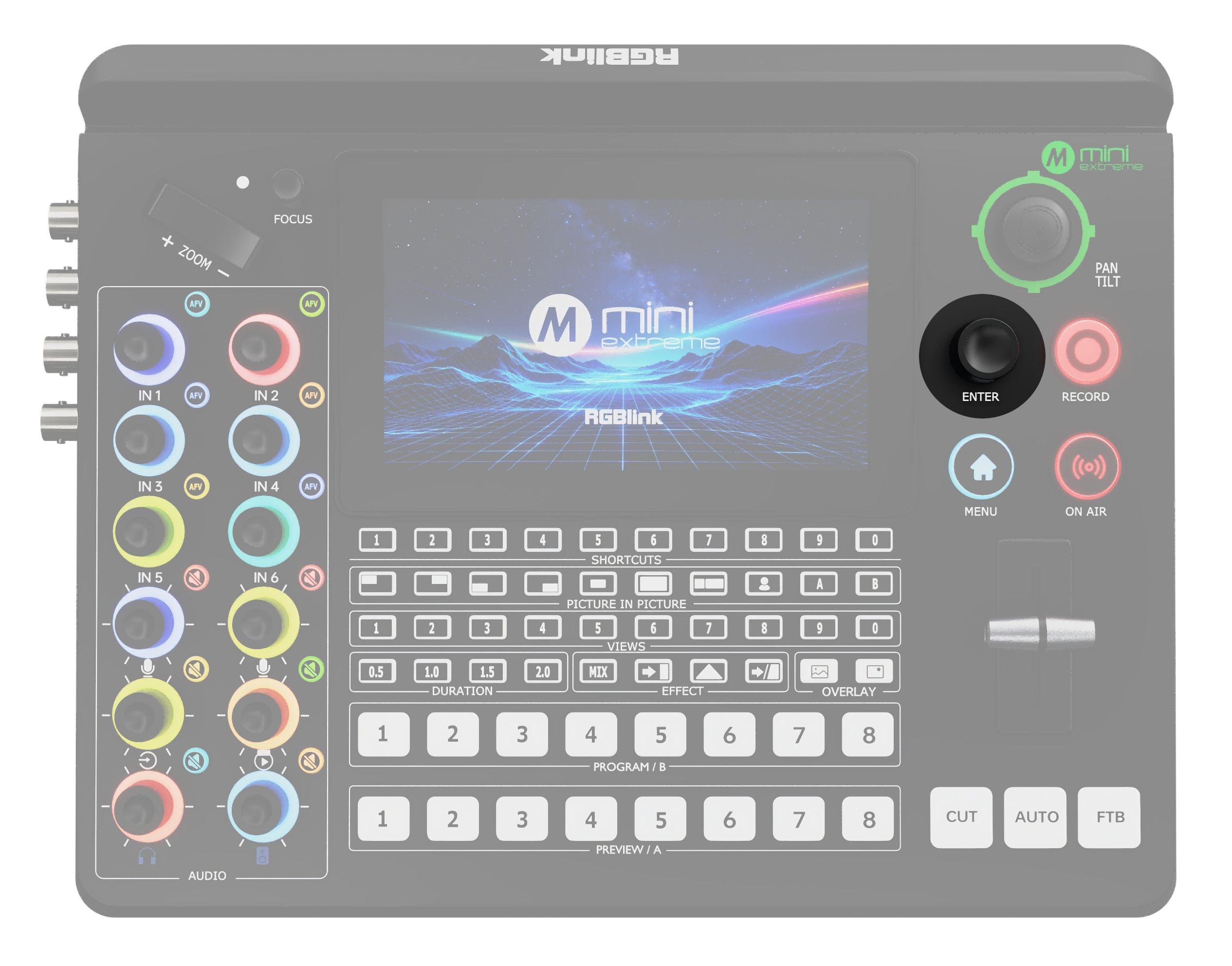
ENTER Button Functions โ—‹ Selects an option. โ—‹ Confirms a selection. โ—‹ In PTZ control mode, turn the knob to adjust the value.
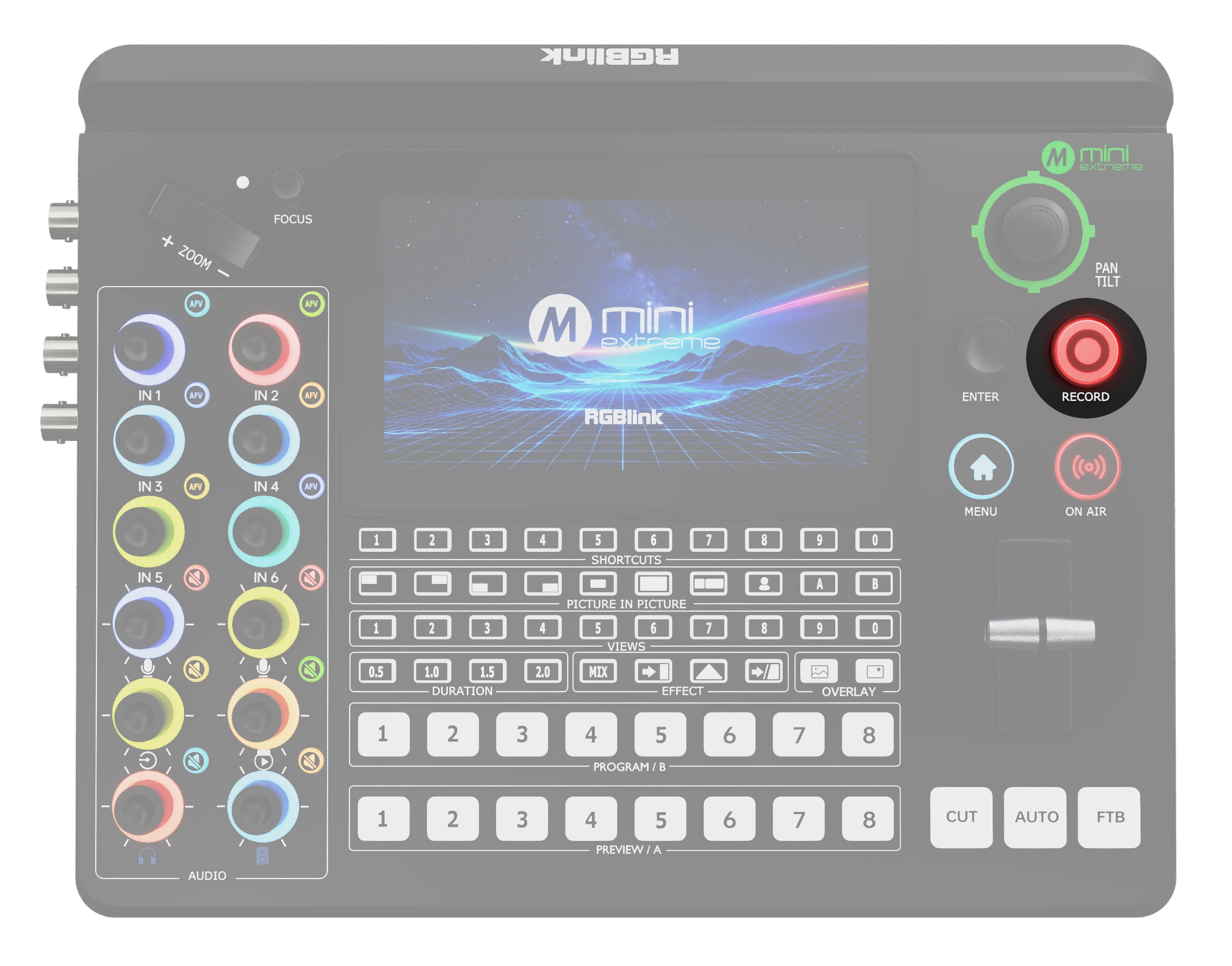
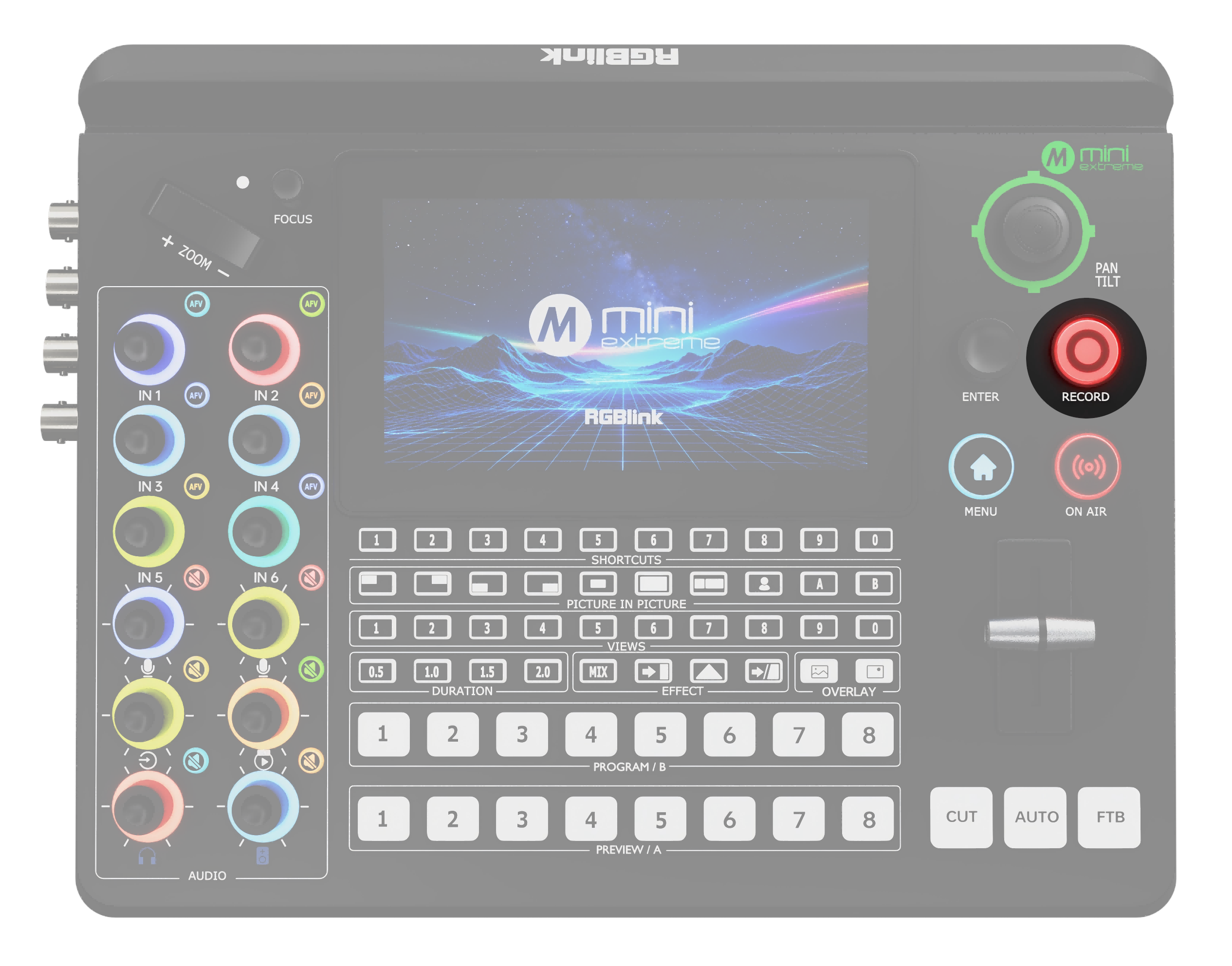
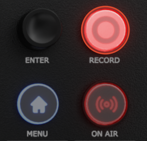
RECORD โ—‹ Connect a USB drive or hard drive to USB-C 1, then press RECORD to start recording. A solid red indicator indicates that recording is in progress. โ—‹ Recording cannot be started when less than 300 MB of storage space remains. โ—‹ During recording, press RECORD to select whether to stop recording. The indicator flashes red while the recording is being saved.
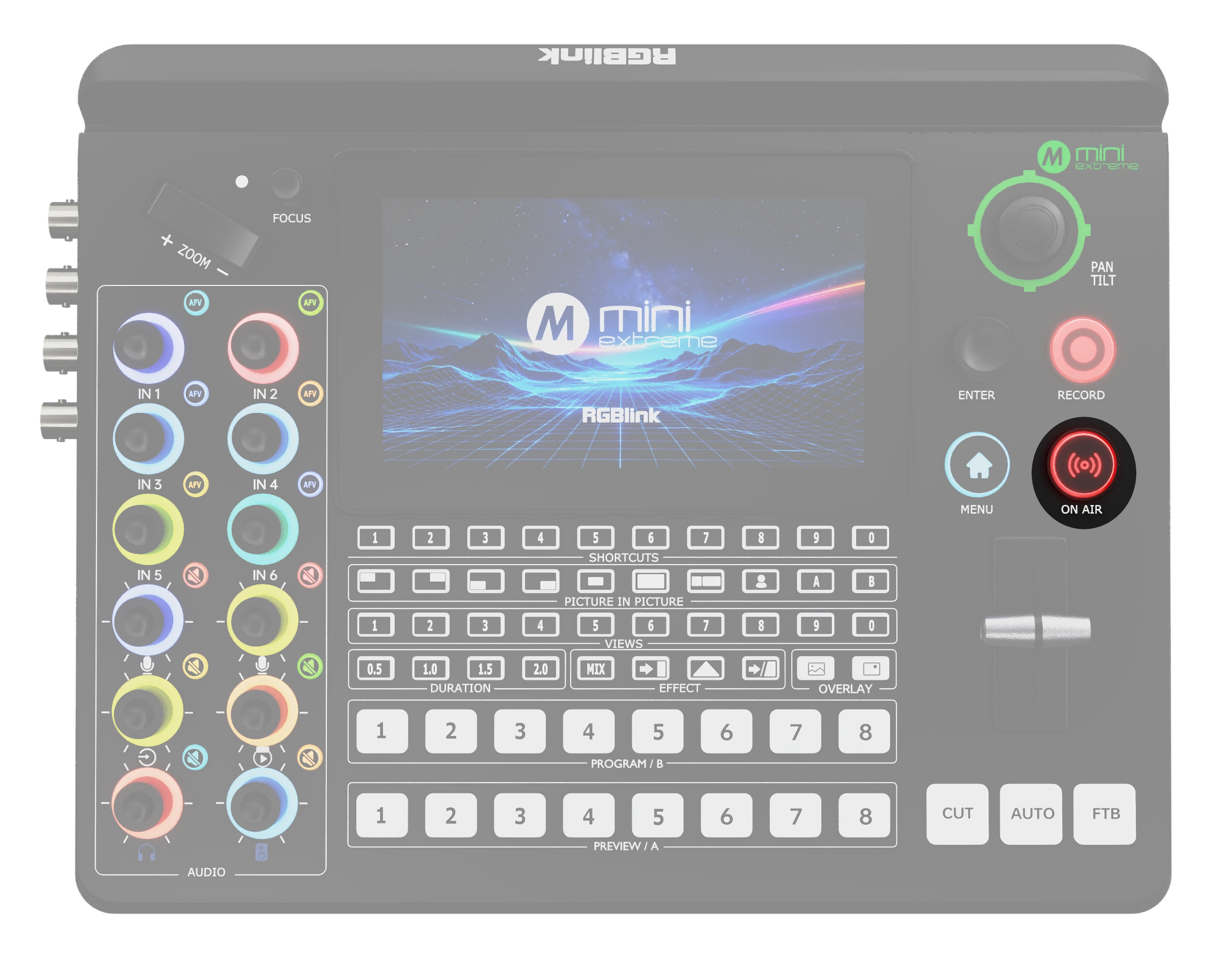
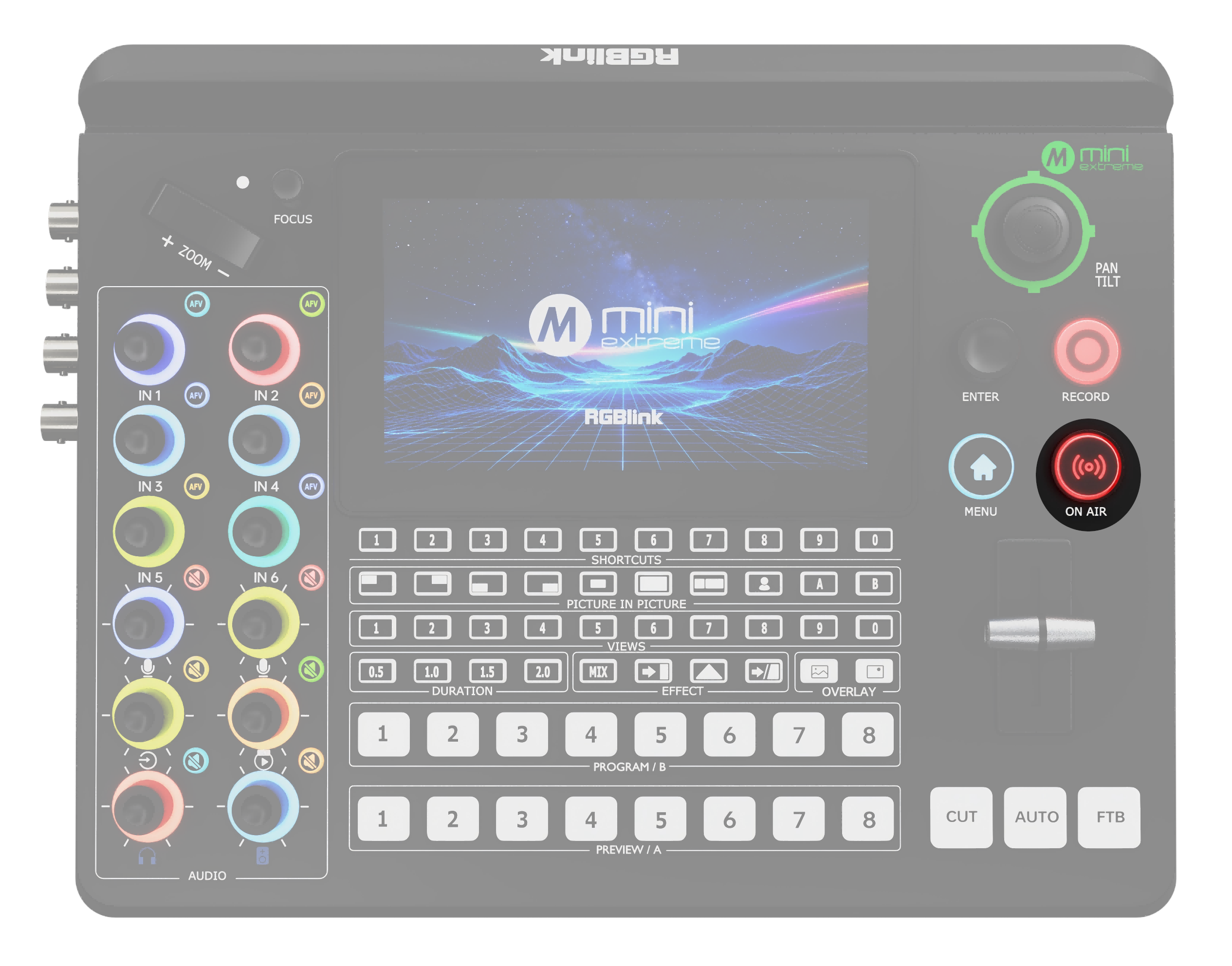
ON AIR โ—‹ When a streaming address is configured, press ON AIR to start streaming. A solid green indicator indicates that streaming is in progress. โ—‹ The indicator flashes red when no streaming address is configured or a configured streaming address fails. โ—‹ During streaming, press ON AIR to select whether to stop streaming. โ—‹ The indicator turns off when streaming ends.

Camera Control

AreaDescription
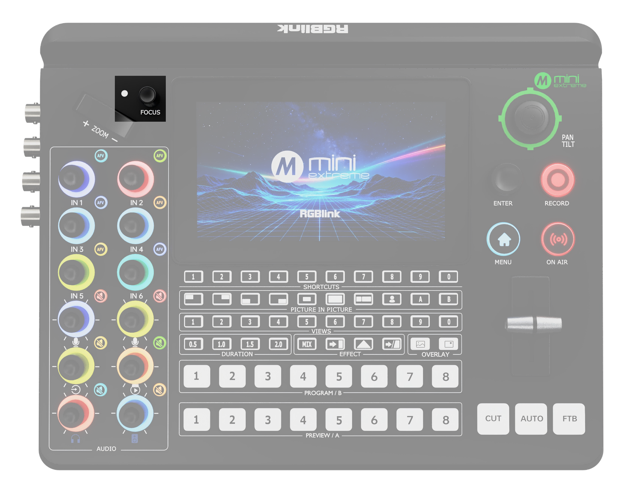
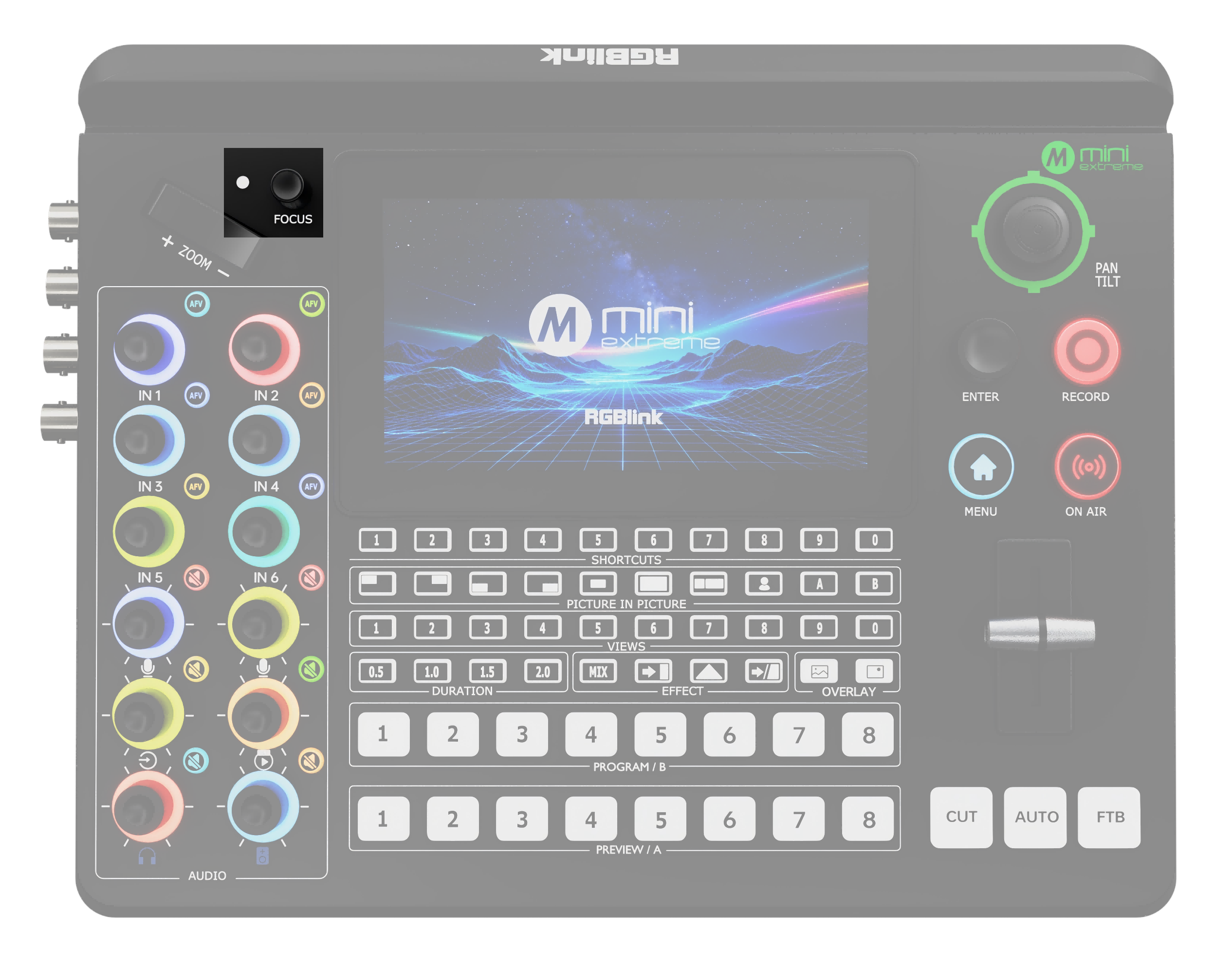
FOCUS Knob and Indicator Focus Status โ—‹ Manual focus: The indicator is off. โ—‹ Auto focus: The indicator lights blue. FOCUS Knob โ—‹ Turn: Manually adjusts focus. โ—‹ Press: Enables auto focus and opens the PTZ page.
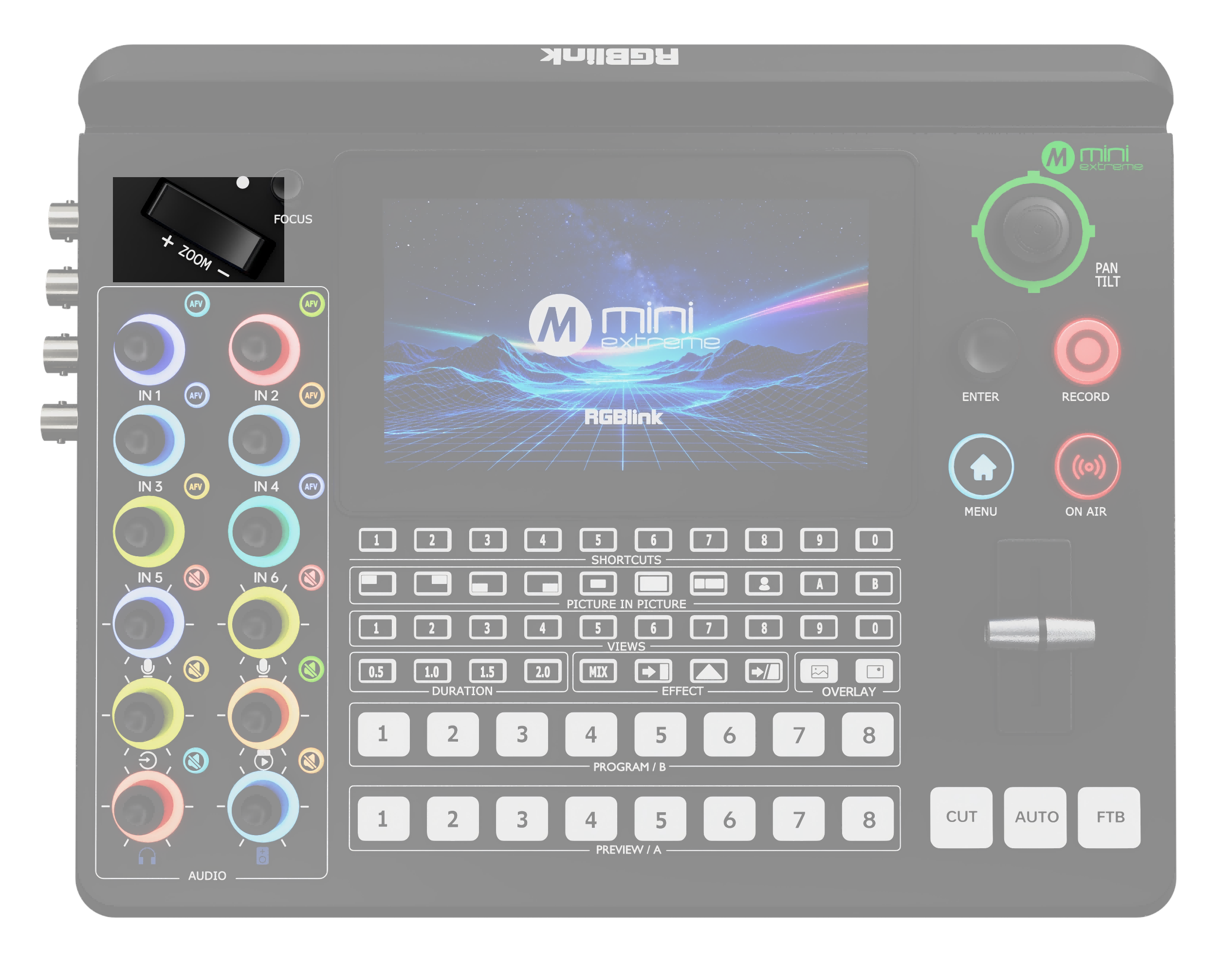
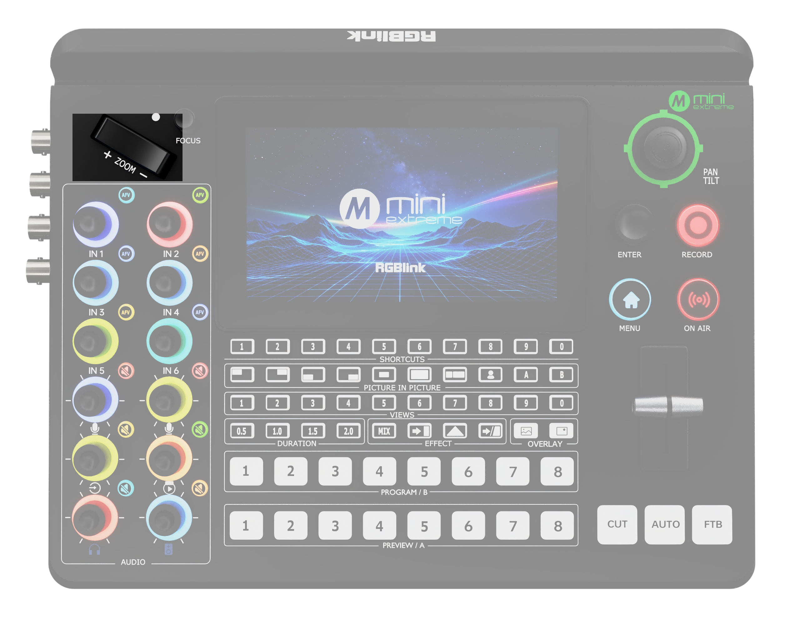
ZOOM Toggle โ—‹ In layer control mode: Adjusts the size of Layer A and Layer B. โ—‹ In camera control mode: Adjusts the camera zoom. Press + to zoom in and - to zoom out.
Five-Direction Joystick Move up, down, left, or right: โ—‹ In layer control mode: Adjusts the layer position. โ—‹ In camera control mode: Controls camera pan and tilt. Press: In camera control mode: Adjusts the pan/tilt speed.

Volume Control

AreaDescription
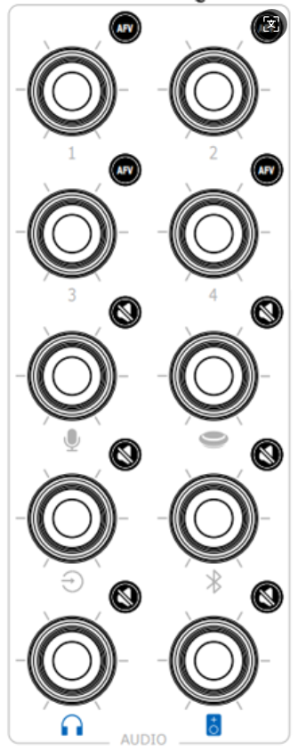
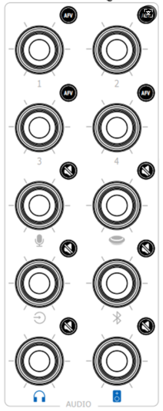
Audio Adjustment Knobs **โ—‹ **The numbered knobs adjust the volume of the embedded audio from HDMI 1โ€“4 and SDI 1โ€“4 inputs. **โ—‹ **The knobs labeled with audio icons adjust the volume of the microphone input, XLR input, monitor output, and program output.
AFV Button Indicator Status โ—‹ Off: AFV is disabled. โ—‹ Solid white: AFV is enabled. Operation โ—‹ Press: Enables or disables AFV.
Indicator Status โ—‹ Off: Mute is disabled. โ—‹ Solid red: Mute is enabled. Operation โ—‹ Press: Enables or disables mute.

Layer Settings

Picture in Picture
AreaDescription
PICTURE-IN-PICTURE Layout Selection Buttons **โ—‹ Press: **Selects the layout for the selected layer. The selected layout button lights solid green.
Chroma Key Button **โ—‹ Press: **Enables chroma keying. Layer B is enabled by default. The button lights solid green.
A/B Layer Selection Buttons โ—‹ Layer A: Main picture. โ—‹ Layer B: Secondary picture. โ—‹ Layers A and B can be combined for PIP. โ—‹ The indicator is off when the layer is disabled or not displayed in Preview. Press a Layer Button โ—‹ Off: Press to select the layer. The indicator lights solid blue. Use ZOOM and the joystick to adjust its size and position. โ—‹ Solid blue: Press another layer button to switch the selected layer. The current layer changes to solid green. โ—‹ Solid blue: Press again to disable the layer. The indicator turns off.

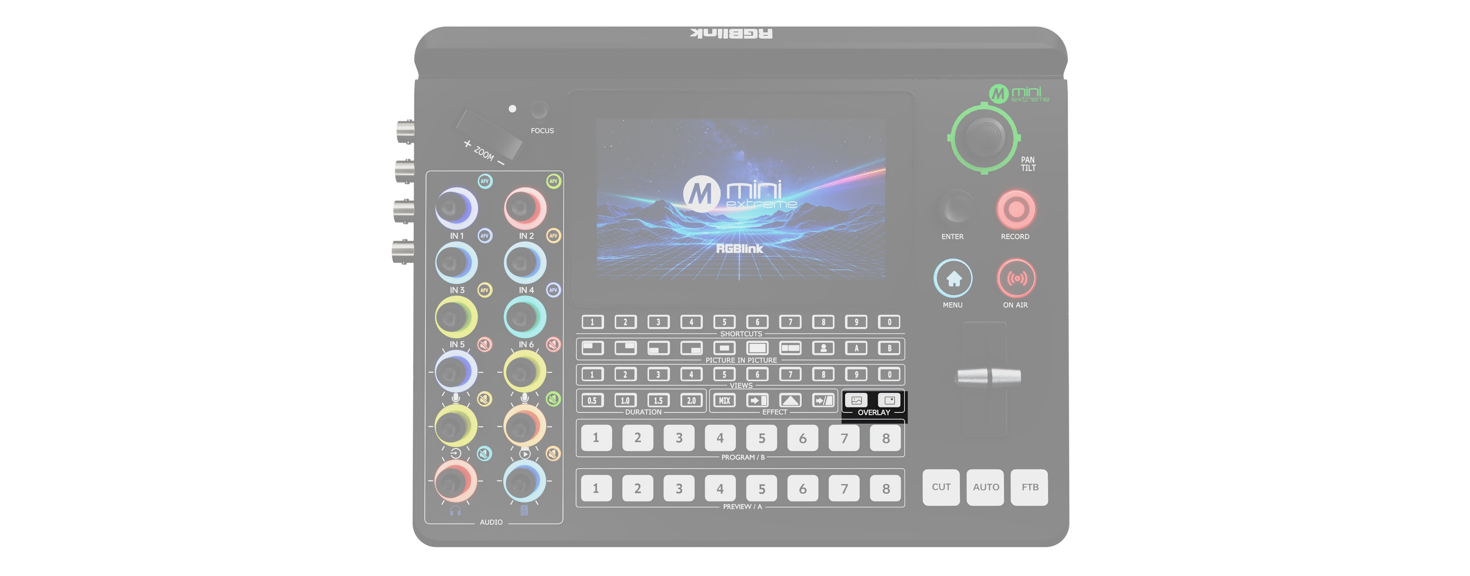
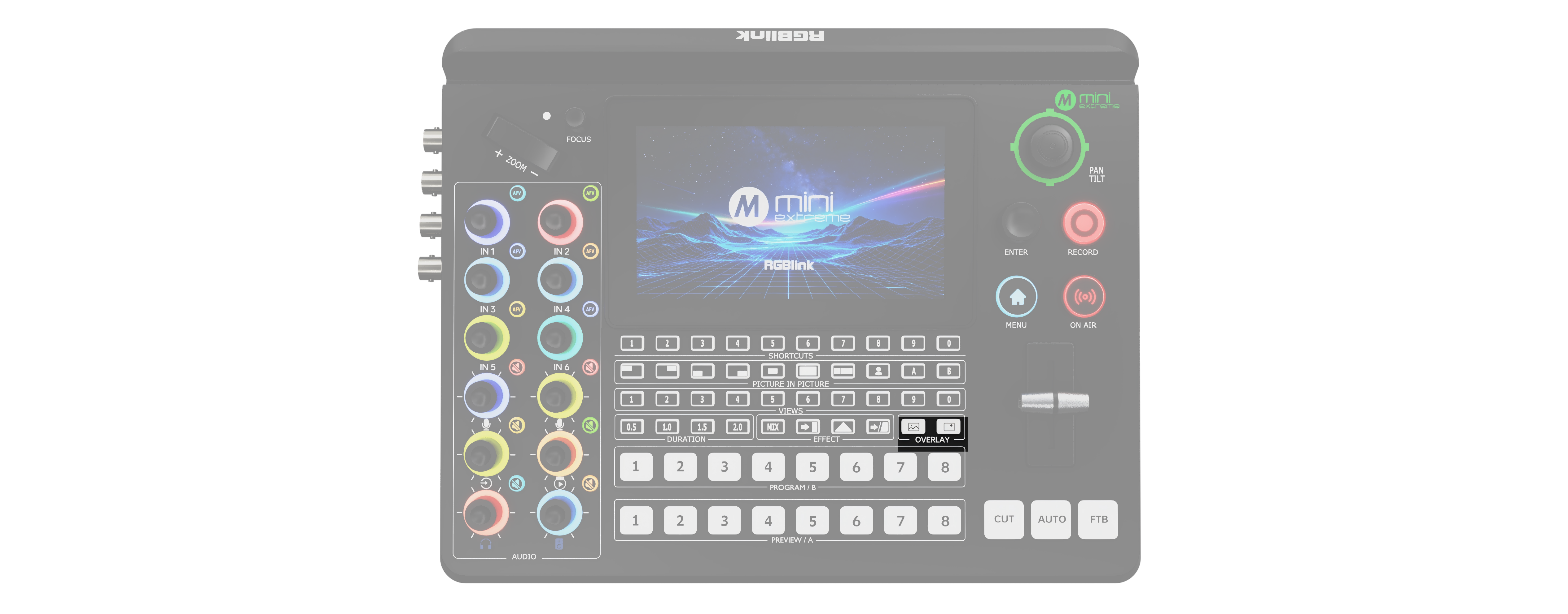
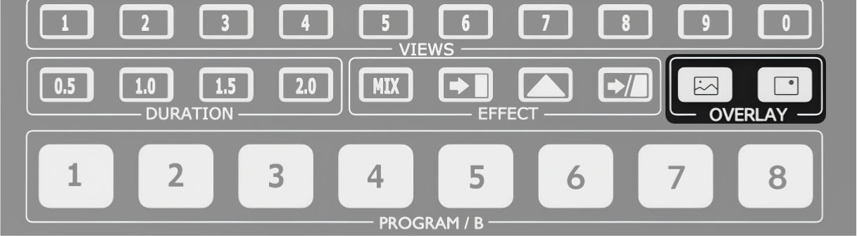
OVERLAY Layer Selection Buttons
AreaDescription
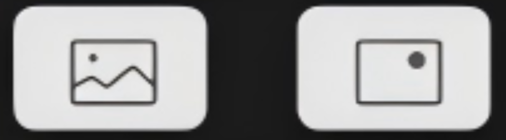
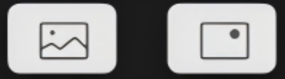
Background Foreground Includes the Background and Foreground buttons. Indicator Status โ—‹ Off: No layer asset is loaded. โ—‹ Solid white: A layer asset is loaded. โ—‹ Solid red: The layer is displayed on the program output. Operation โ—‹ Solid white: Press to add the layer to the program output. The indicator changes to solid red. โ—‹ Solid red: Press to remove the layer from the program output. The indicator changes to solid white.
AreaDescription
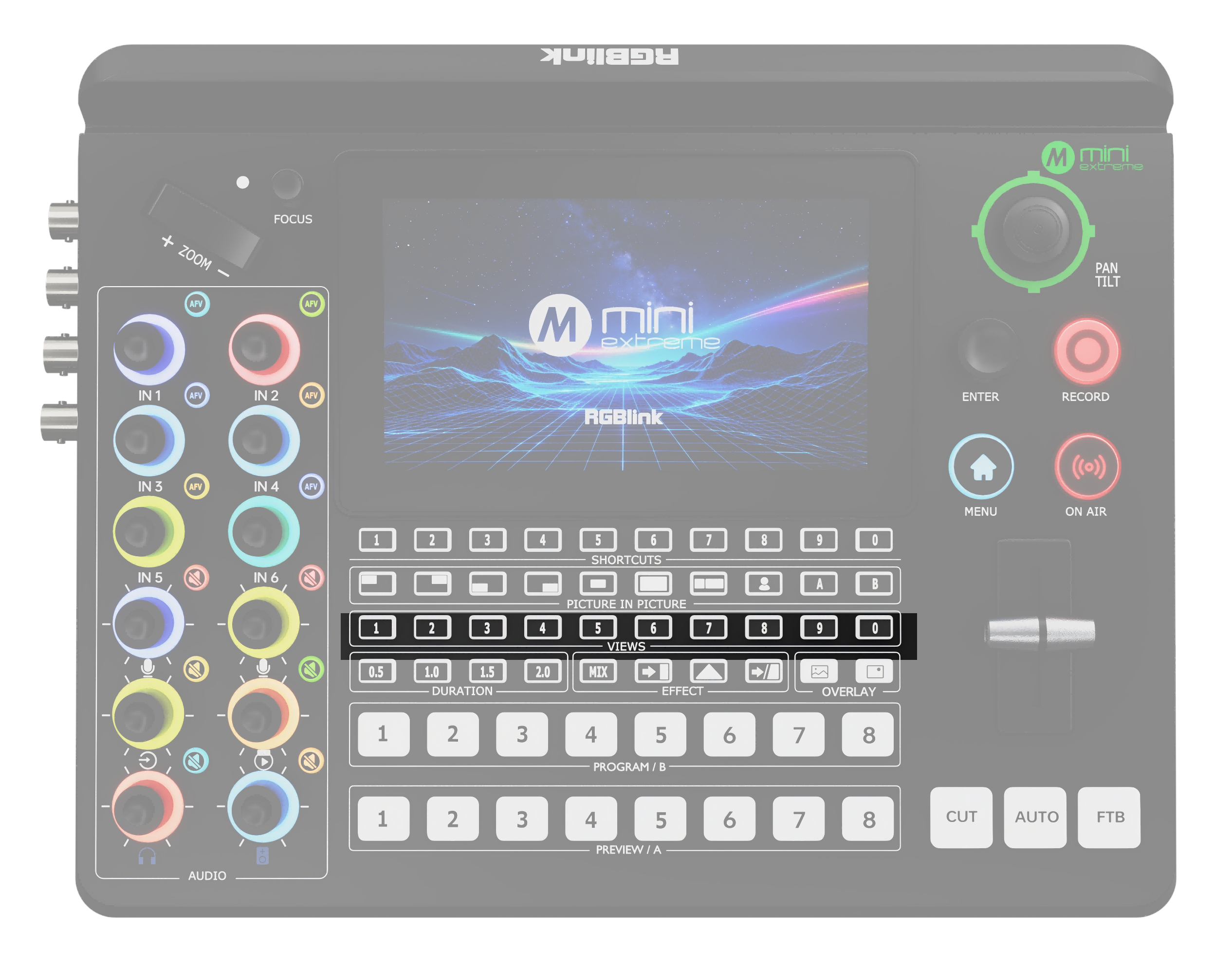
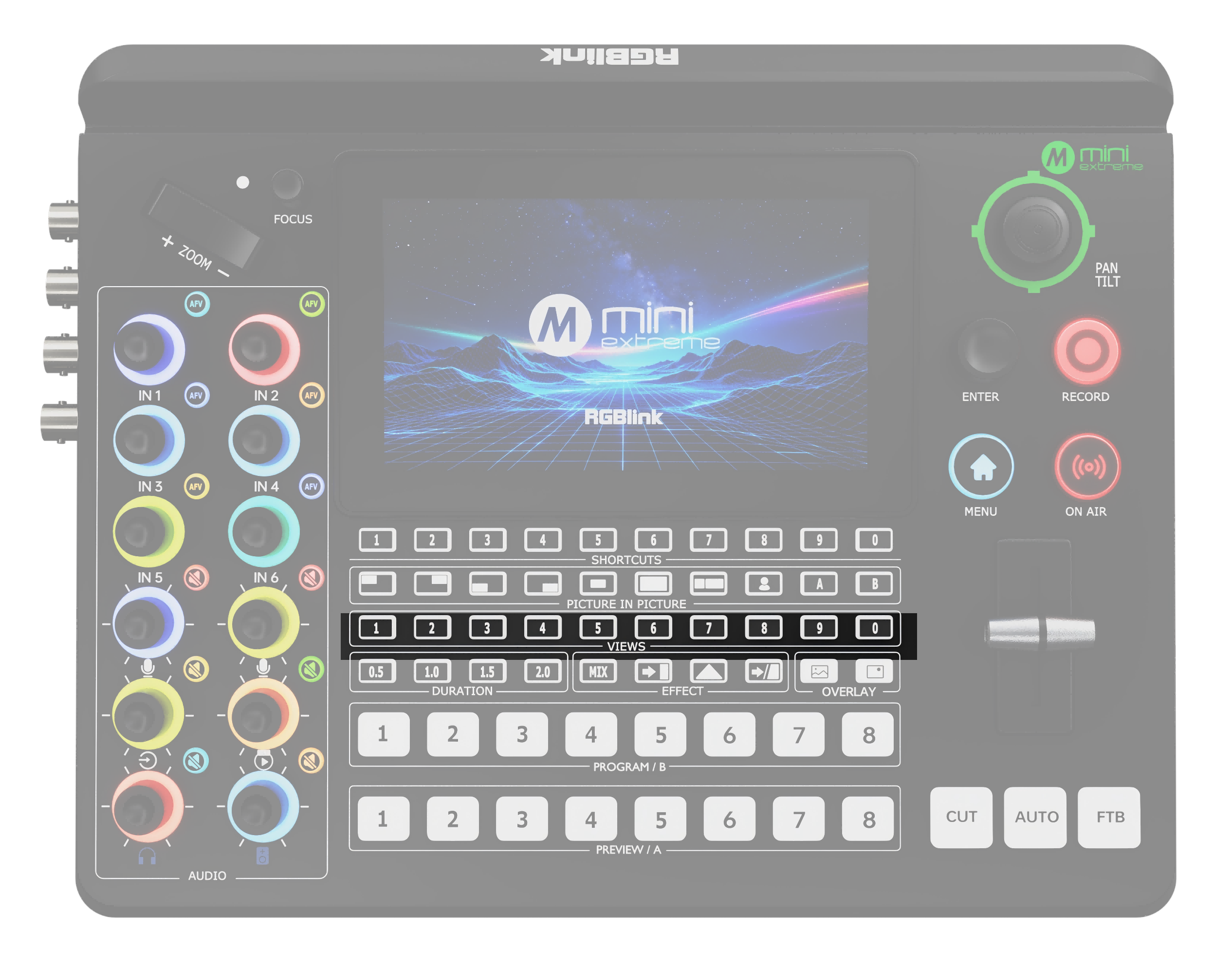
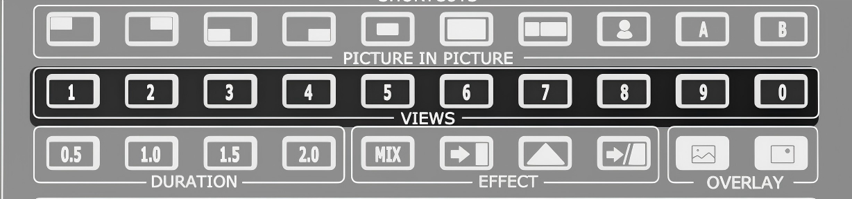
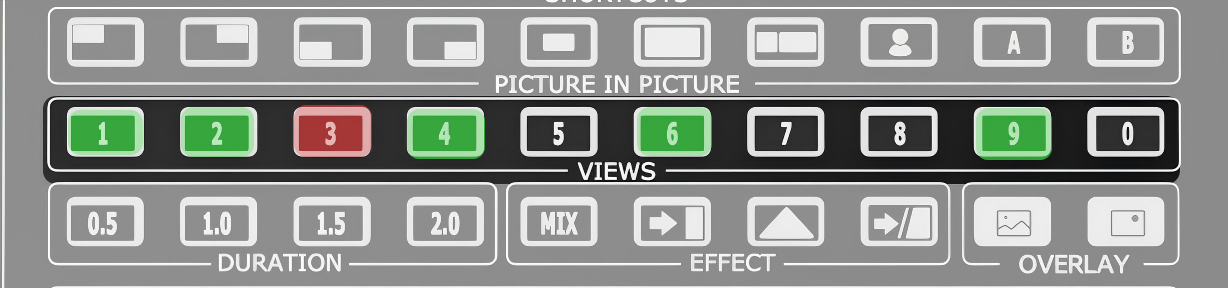
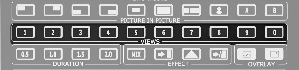
VIEWS Recall Buttons Indicator Status โ—‹ Solid green: view saved. โ—‹ Solid red: view recalling. โ—‹ Off: No view is saved. Operation โ—‹ Indicator off: Press and hold to add a view. The indicator lights solid green when the view is saved. โ—‹ Solid green: Press to recall the view to Preview. The indicator changes to solid red. โ—‹ Recall another view: The button for the view being recalled changes to solid green, while the button for the current scene changes to solid red.
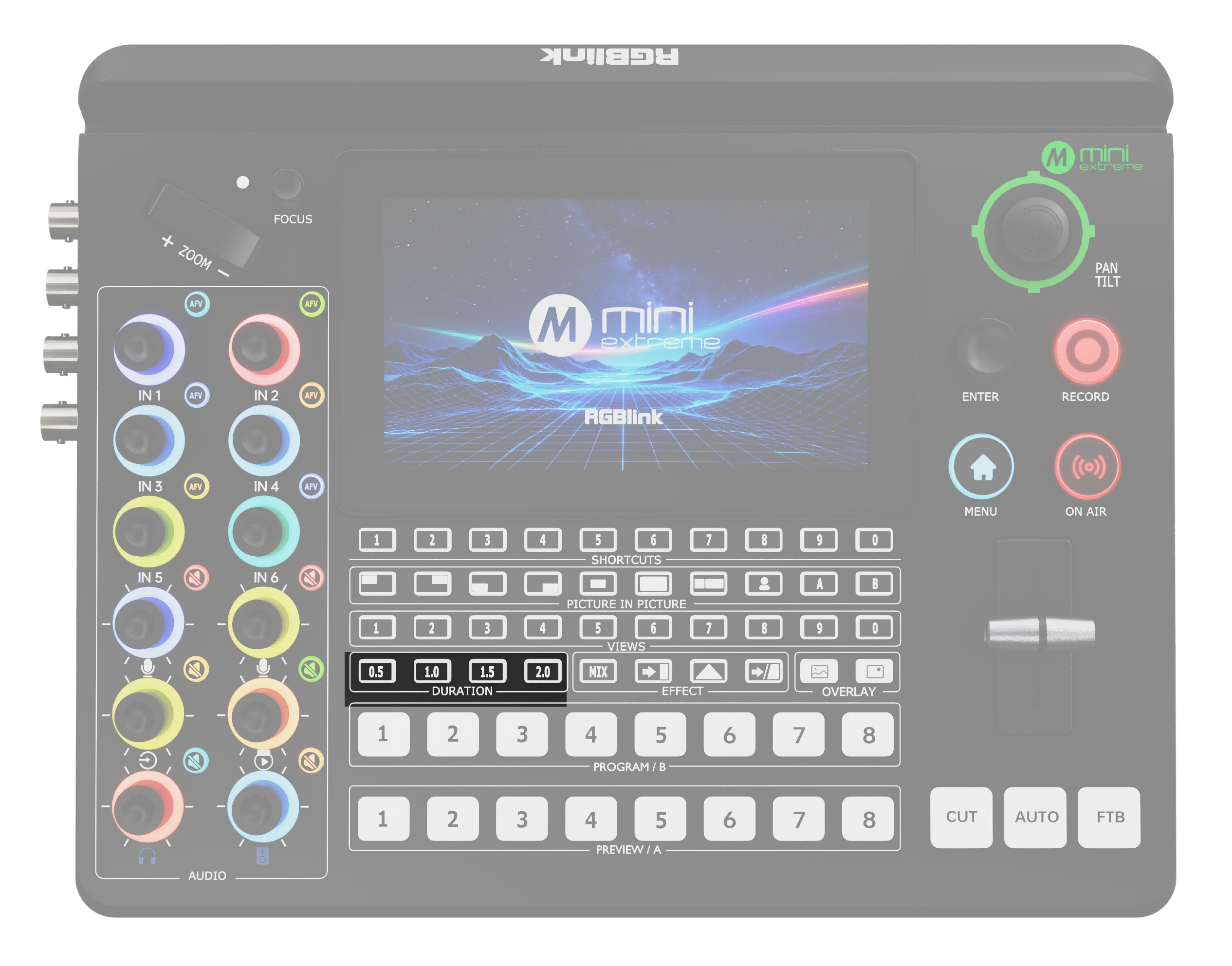
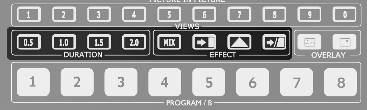
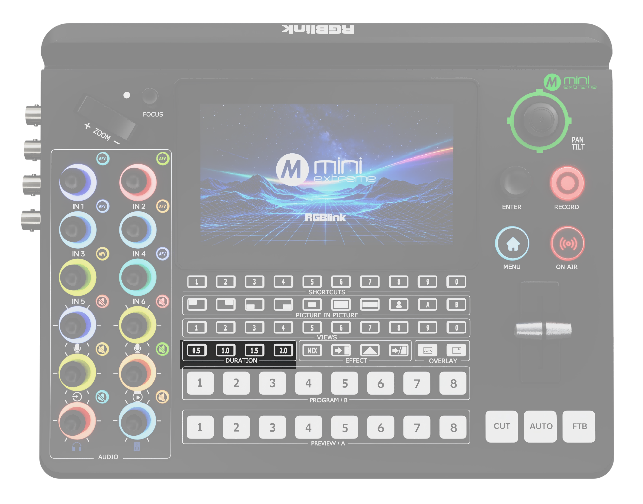
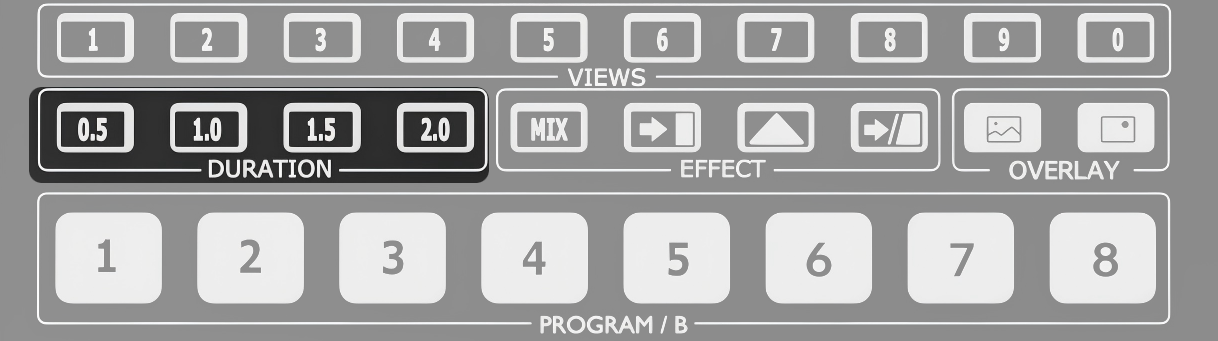
DURATION Transition Duration Buttons โ—‹ Default: 1.0 s โ—‹ Options: 0.5 / 1.0 / 1.5 / 2.0 s โ—‹ Selected: Solid white
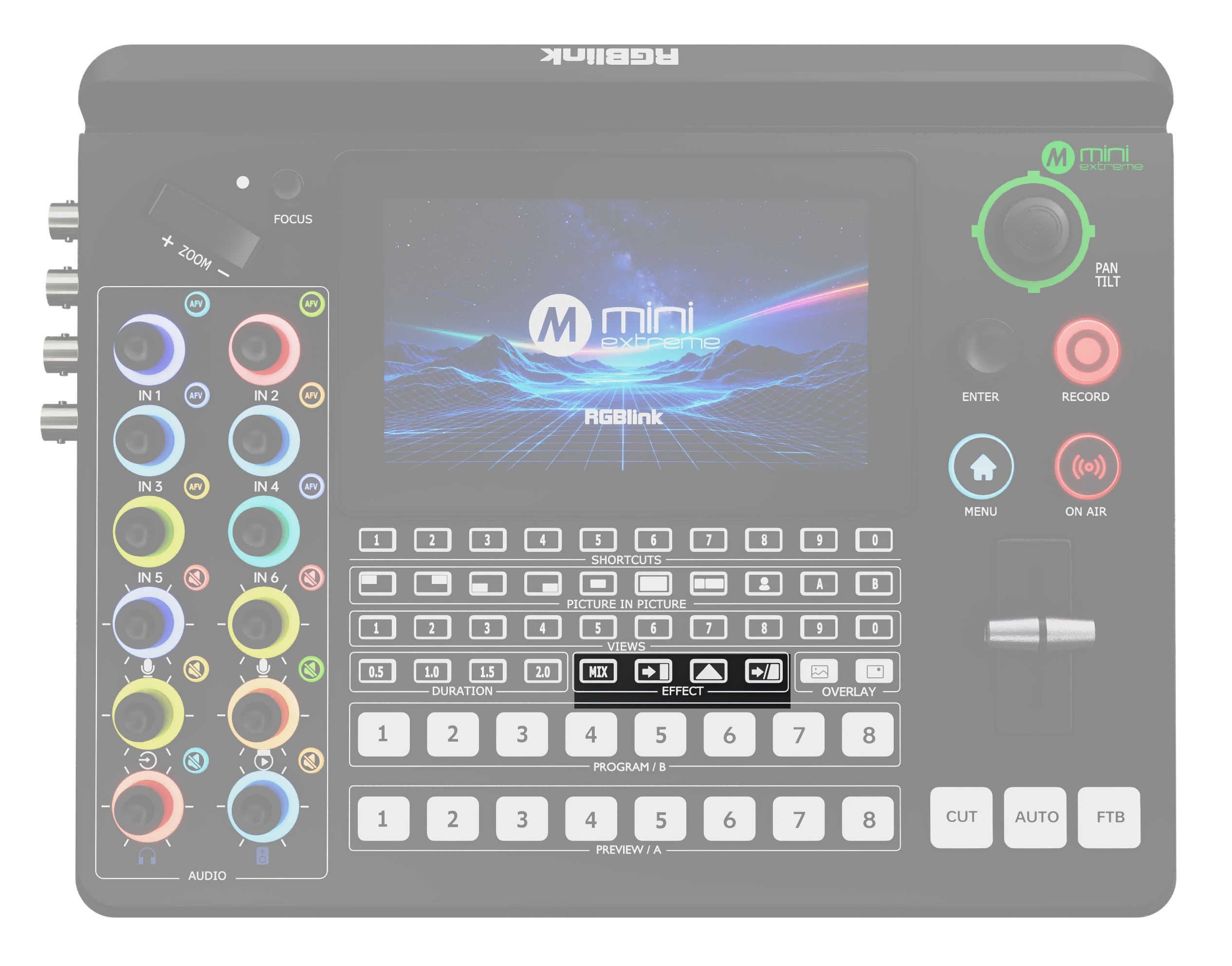
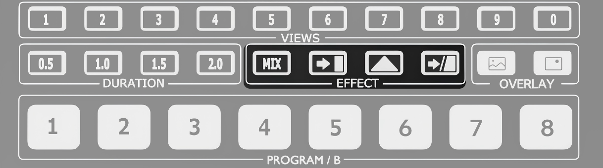
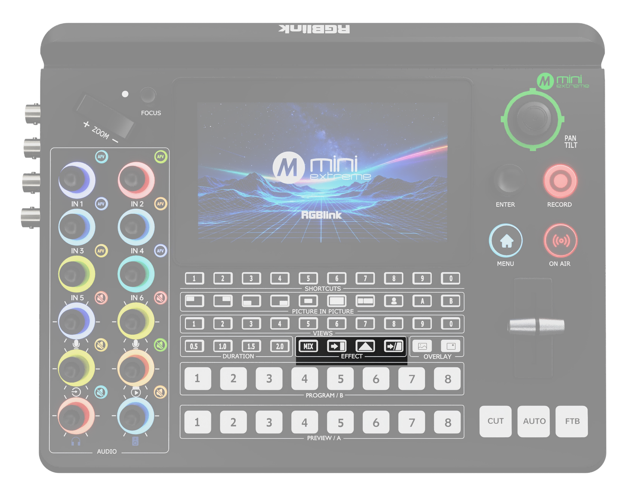
EFFECT Transition Effect Buttons โ—‹ Default: MIX (fade) โ—‹ For more effects, go to MENU > EFFECT. โ—‹ Selected: Solid white
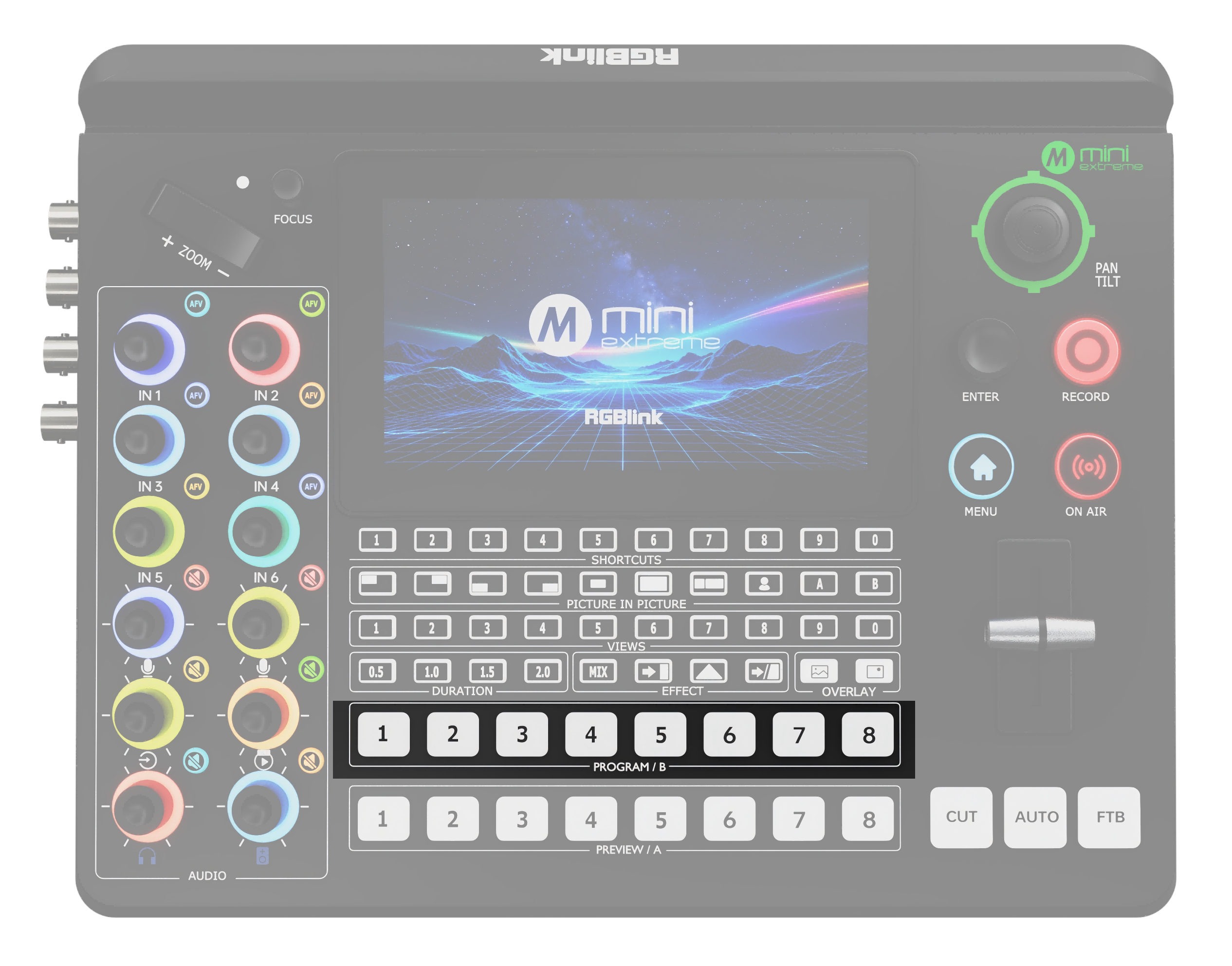
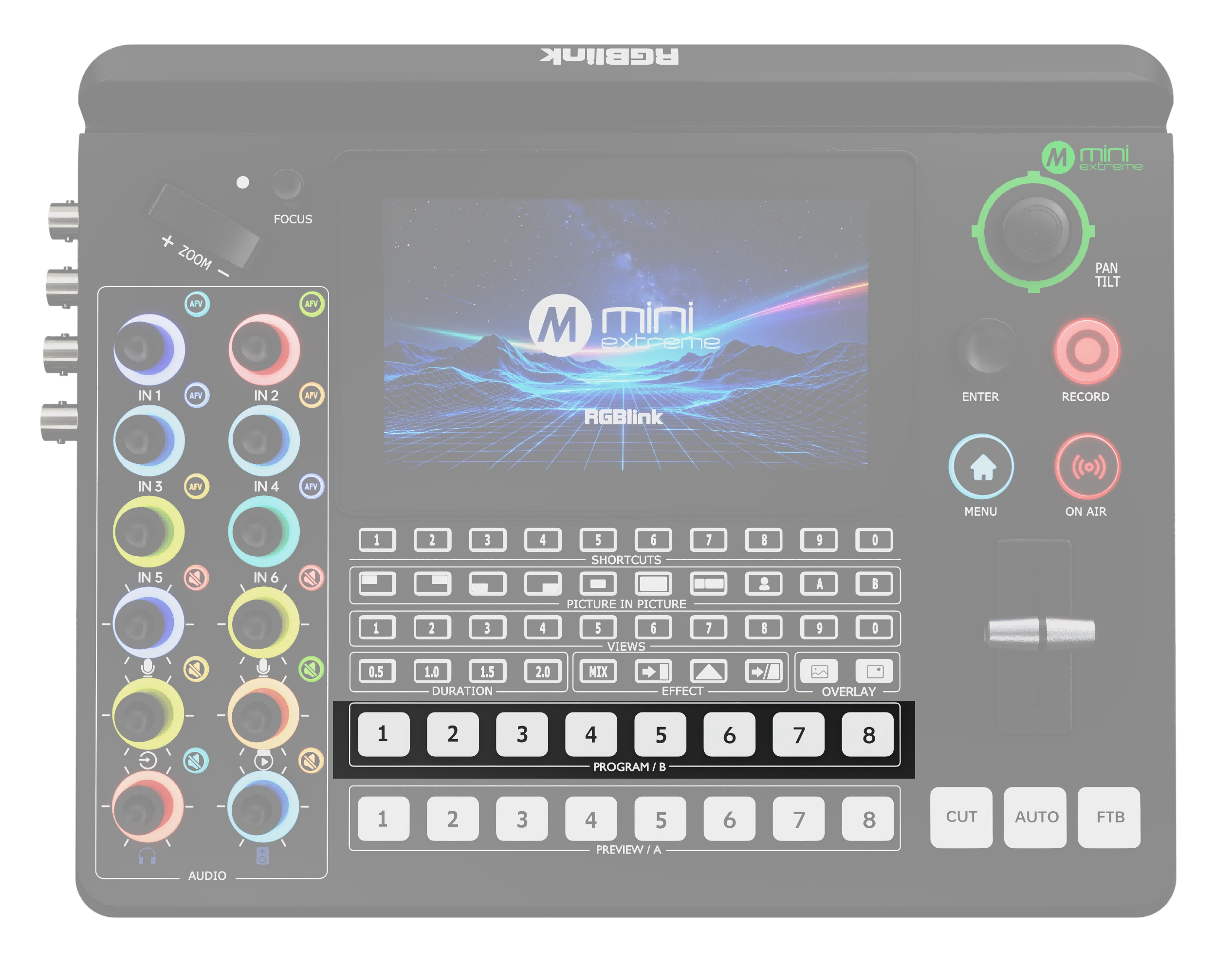
PROGRAM Program Output Selection Buttons Button Assignment โ—‹ 1โ€“4: HDMI 1โ€“4 โ—‹ 5: SDI 1 / SDI 2 โ—‹ 6: SDI 3 / SDI 4 โ—‹ 7โ€“8: UVC / NDI Operation โ—‹ Press to switch the PROGRAM output to the selected input.
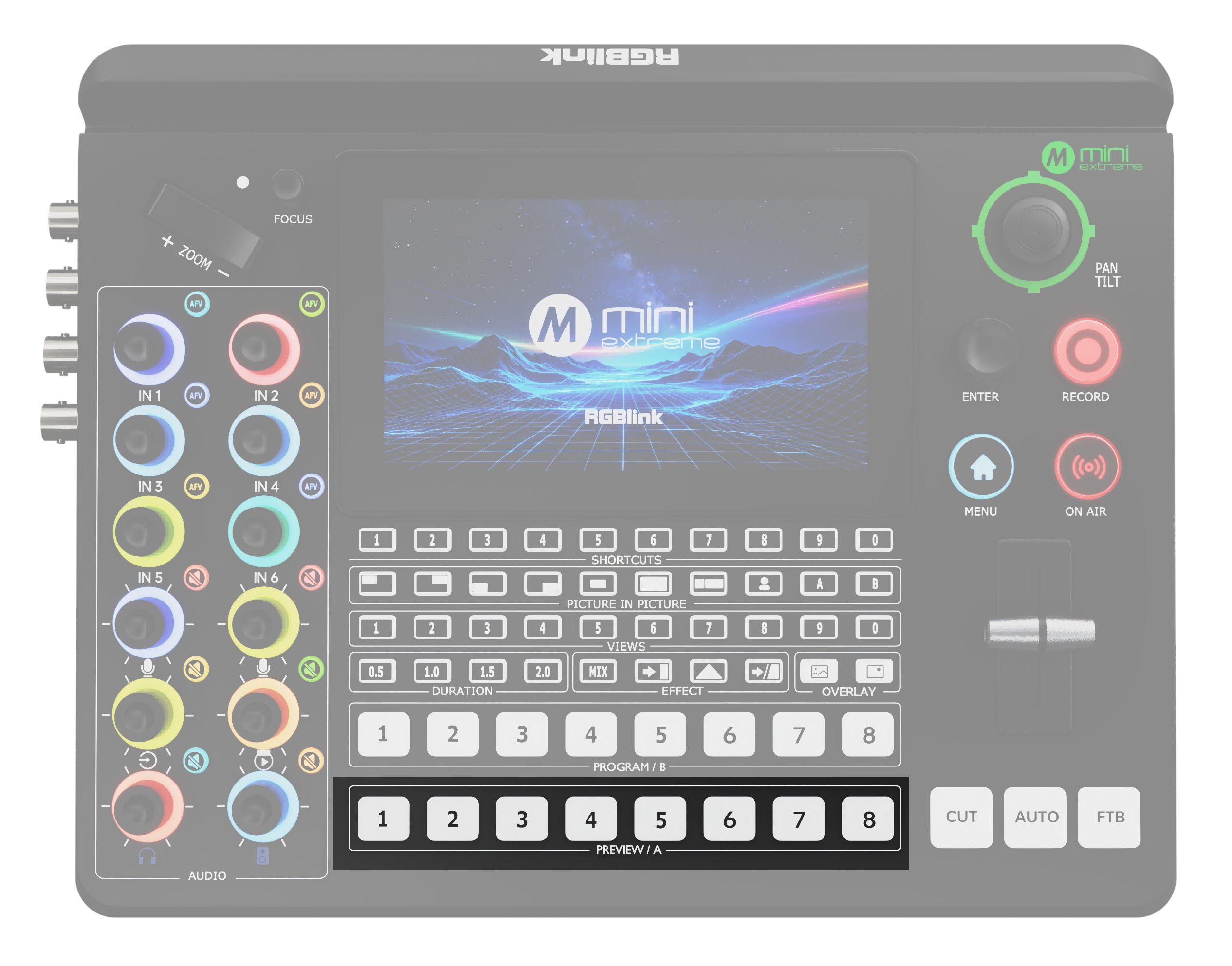
PREVIEW Preview Output Selection Buttons Button Assignment โ—‹ Assign signals via MENU > Input. โ—‹ 1โ€“6: HDMI 1โ€“4 / SDI 1โ€“4 (IN1โ€“IN6) โ—‹ 7โ€“8: IN7โ€“IN8 Operation โ—‹ Press to switch the PREVIEW output to the selected input.

Transition

AreaDescription
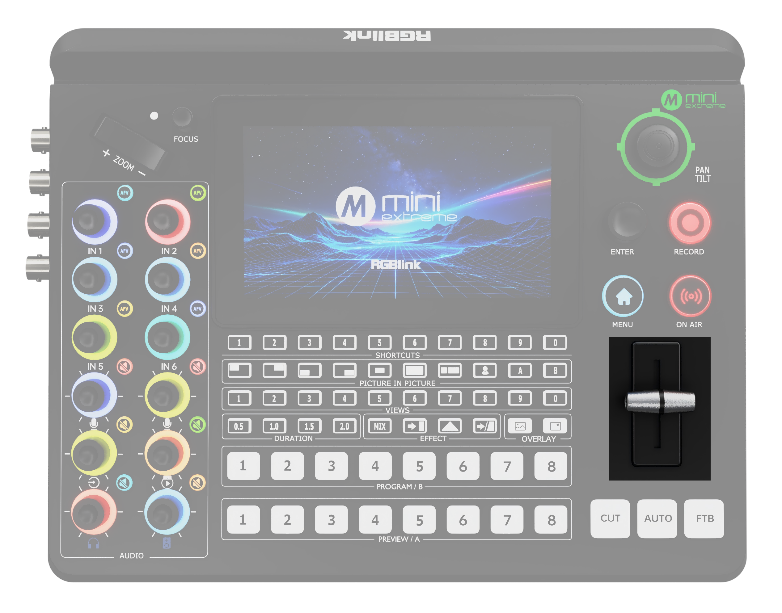
T-Bar Manually transitions from Preview to Program using the selected transition effect.
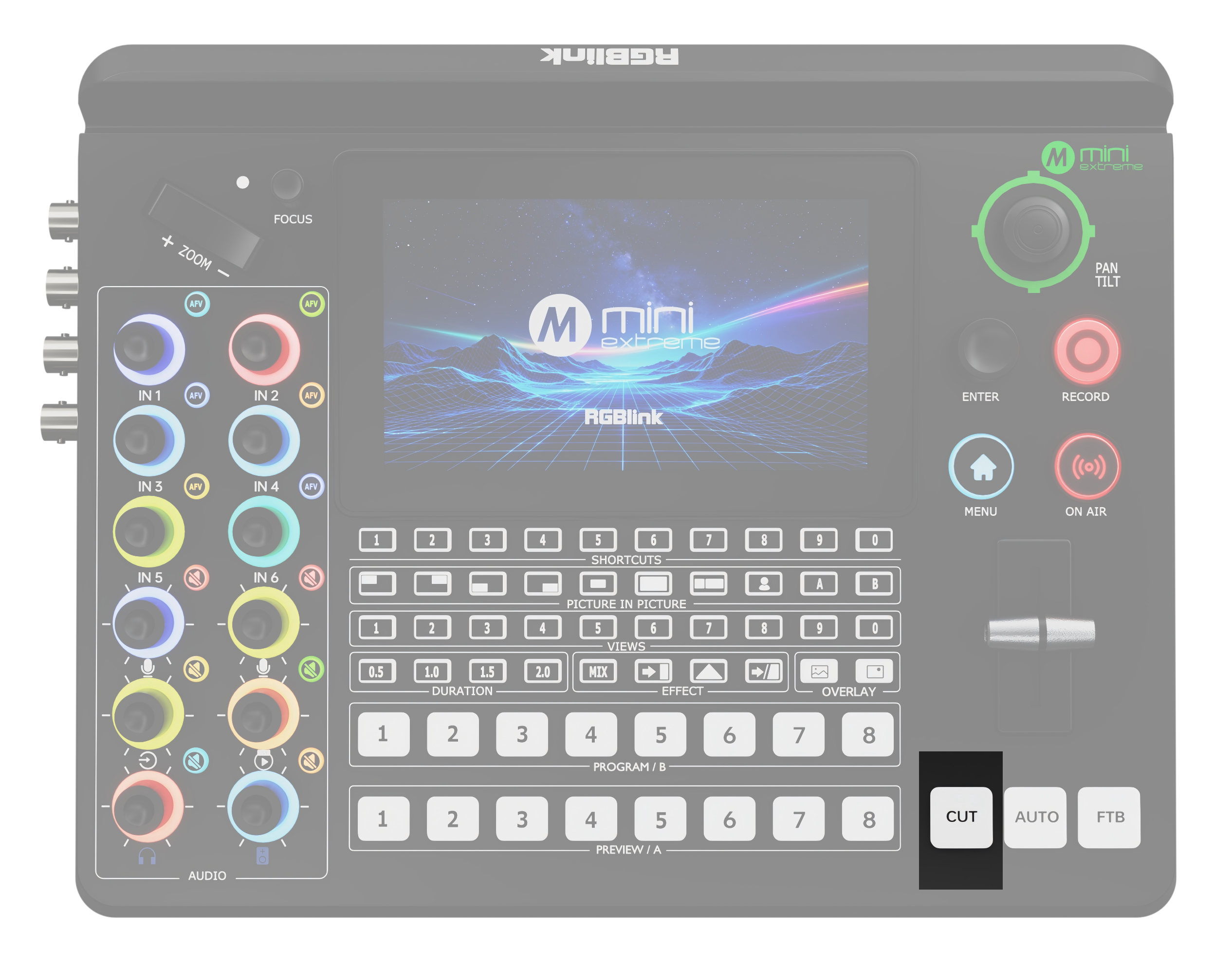
CUT Press to switch between Preview and Program without a transition effect.
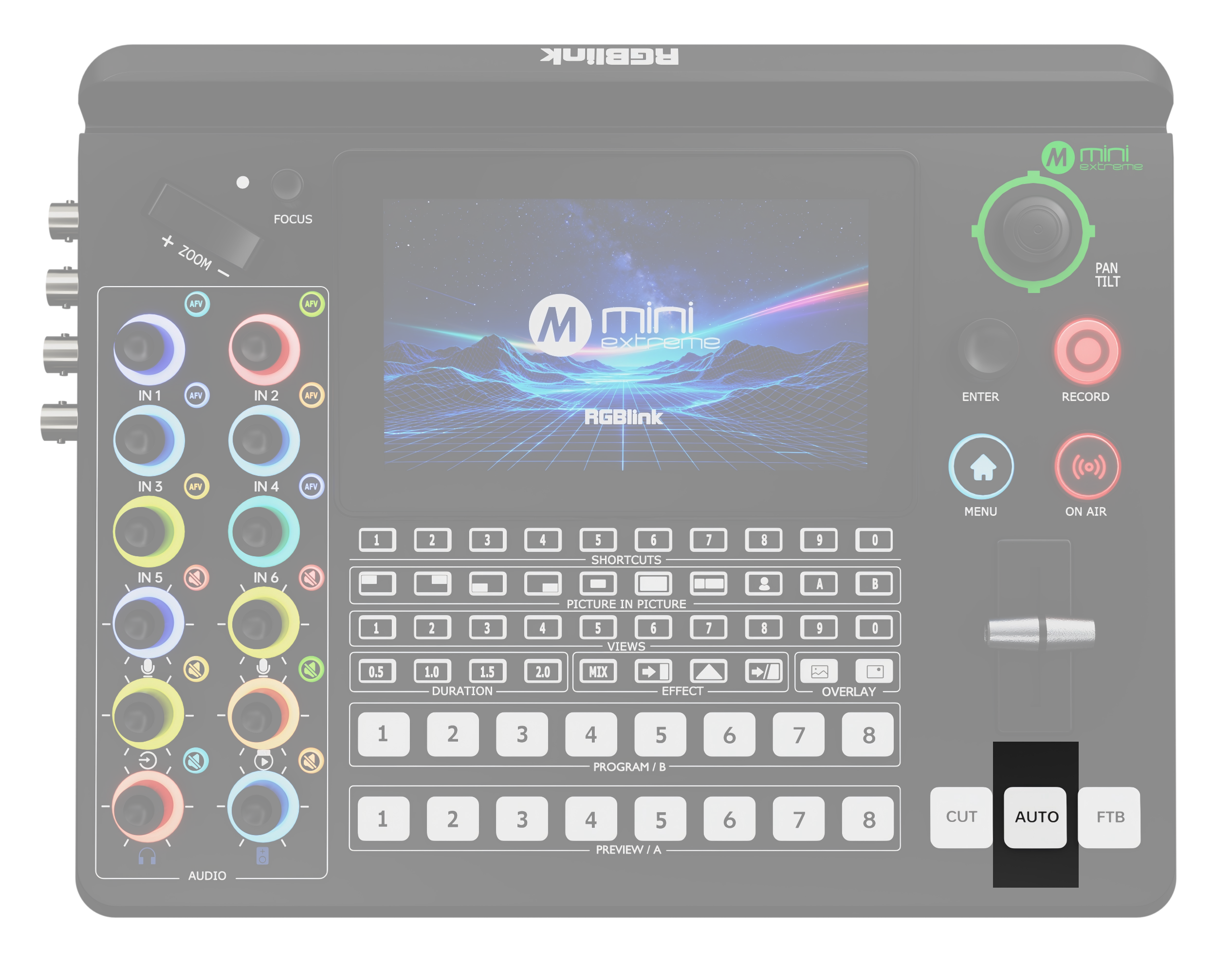
AUTO โ—‹ Press to execute the selected transition effect at the selected duration. โ—‹ Flashing red: Transition in progress. โ—‹ Off: Transition complete.
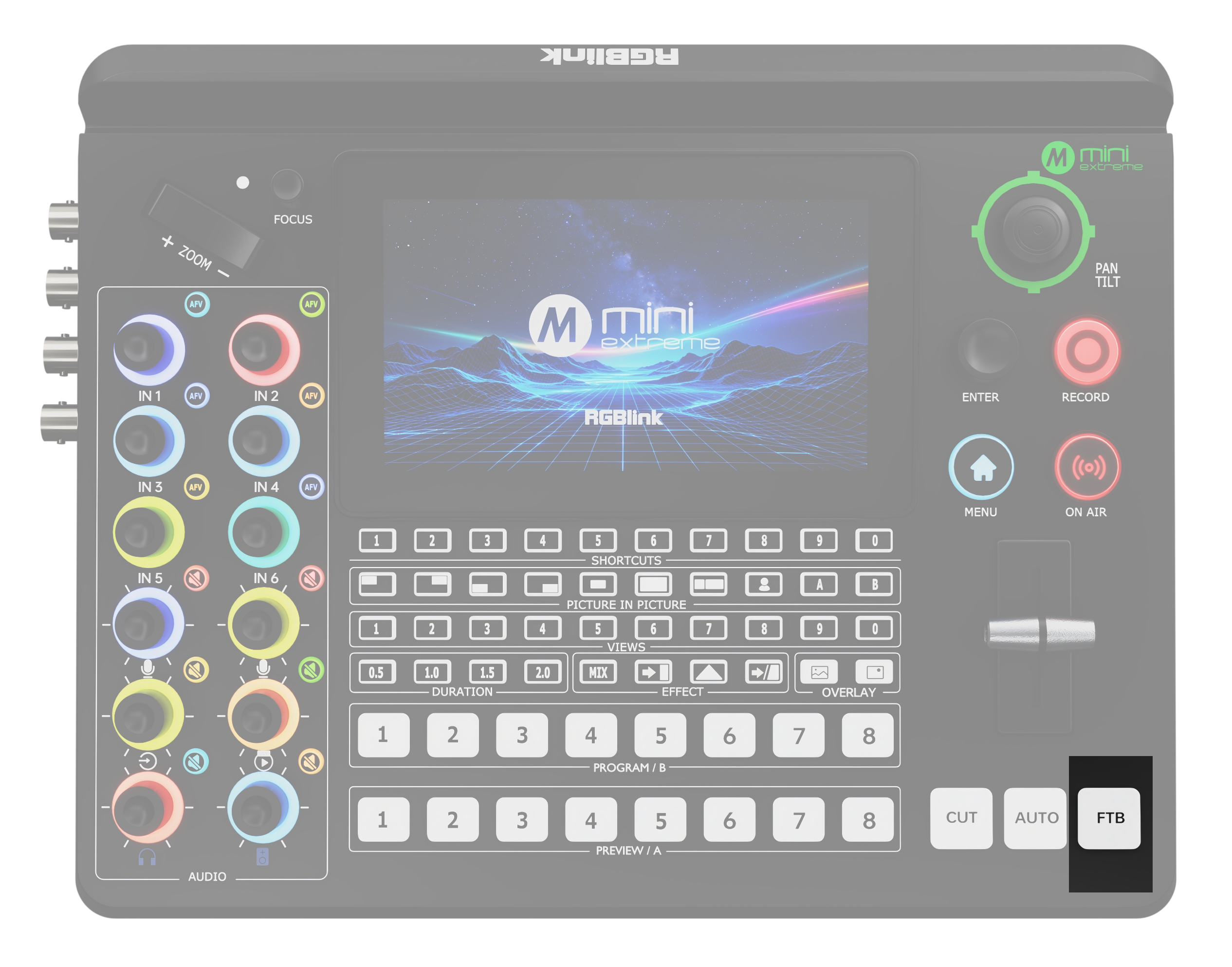
FTB (Fade to Black) Press to toggle the Program output: โ—‹ Off: Displays the actual Program output. โ—‹ Solid red: Fades the Program output to black.

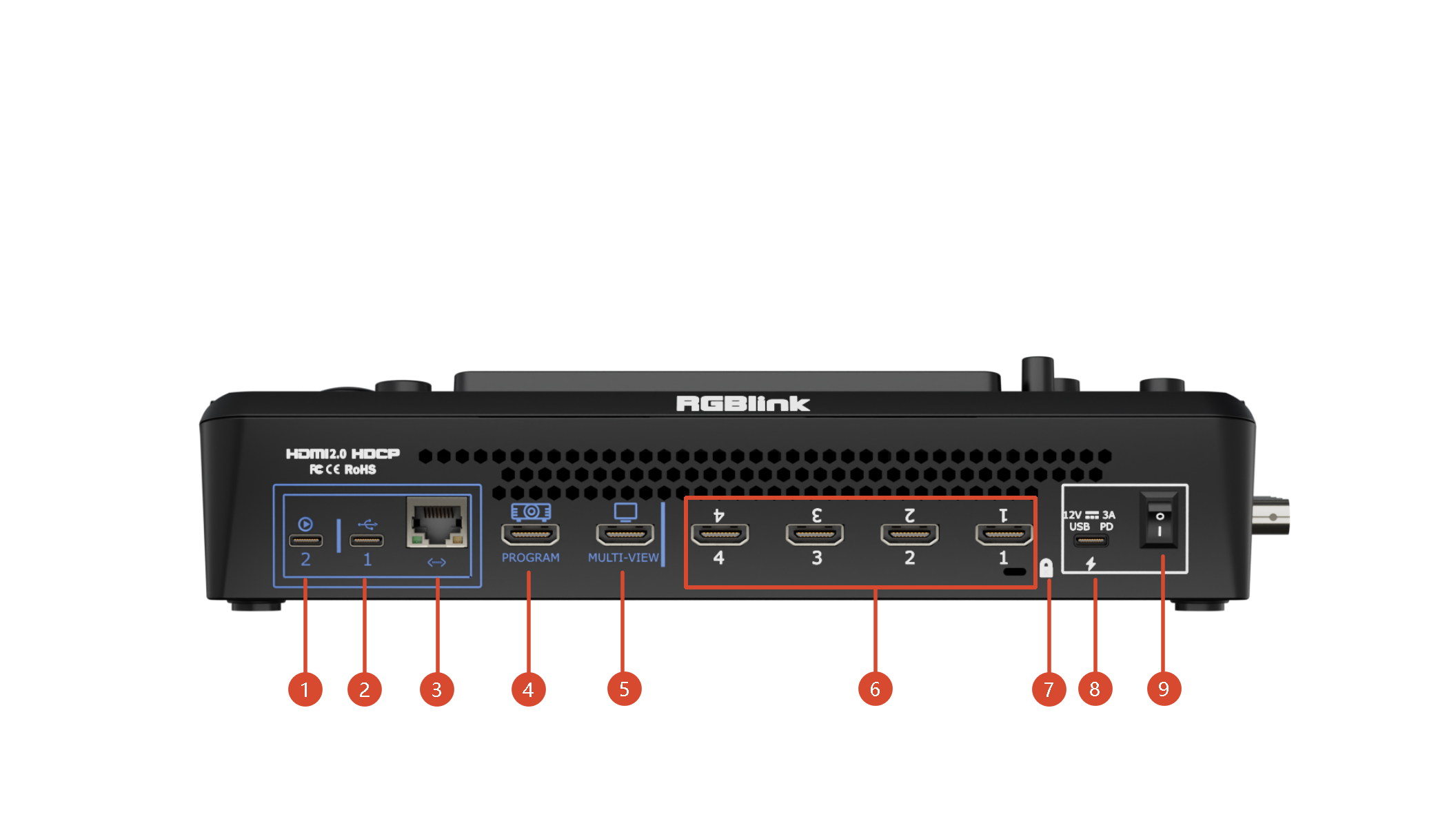
2.1.3Ports Info

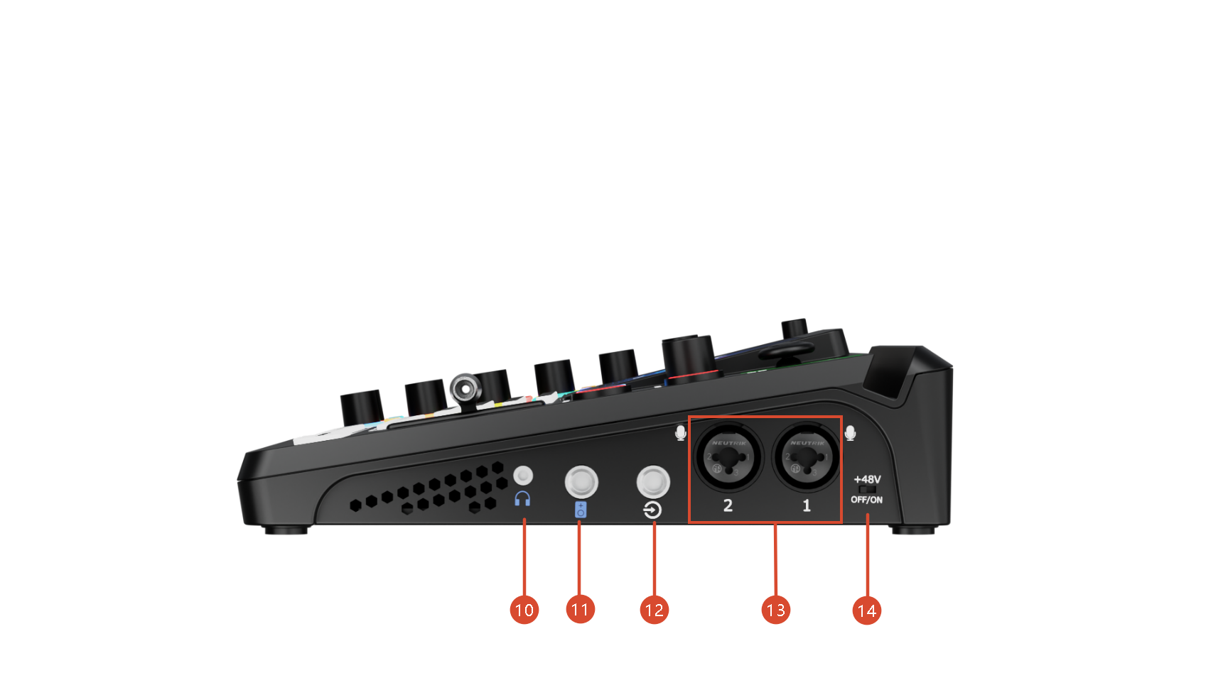
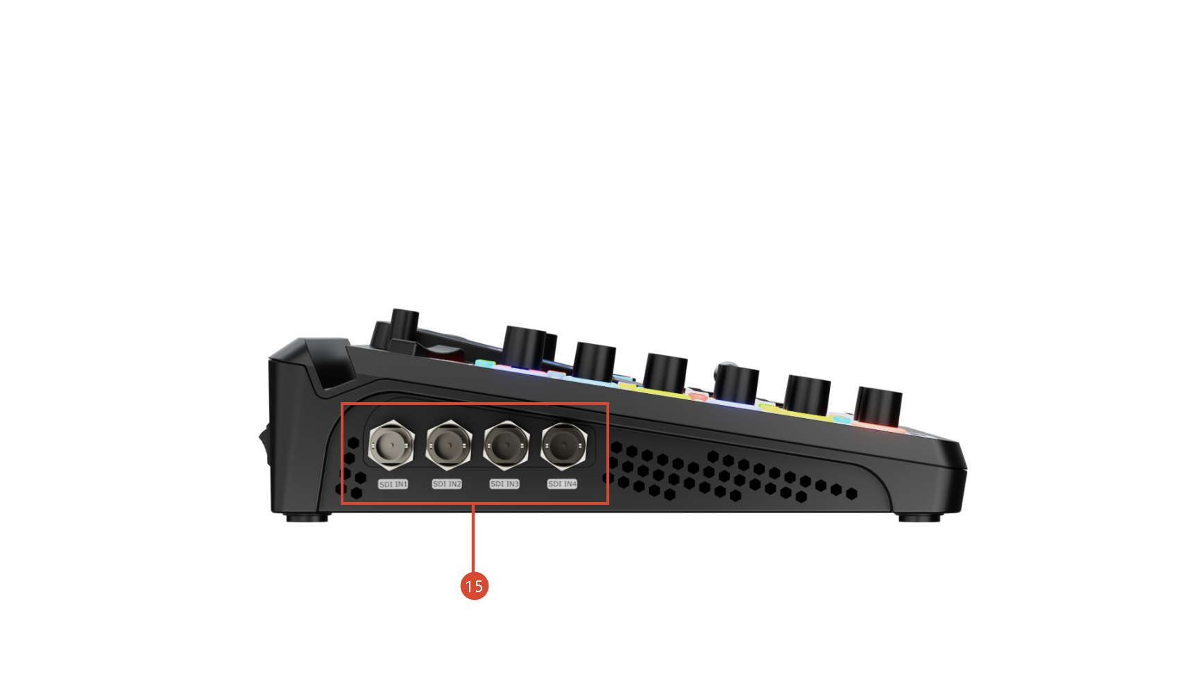
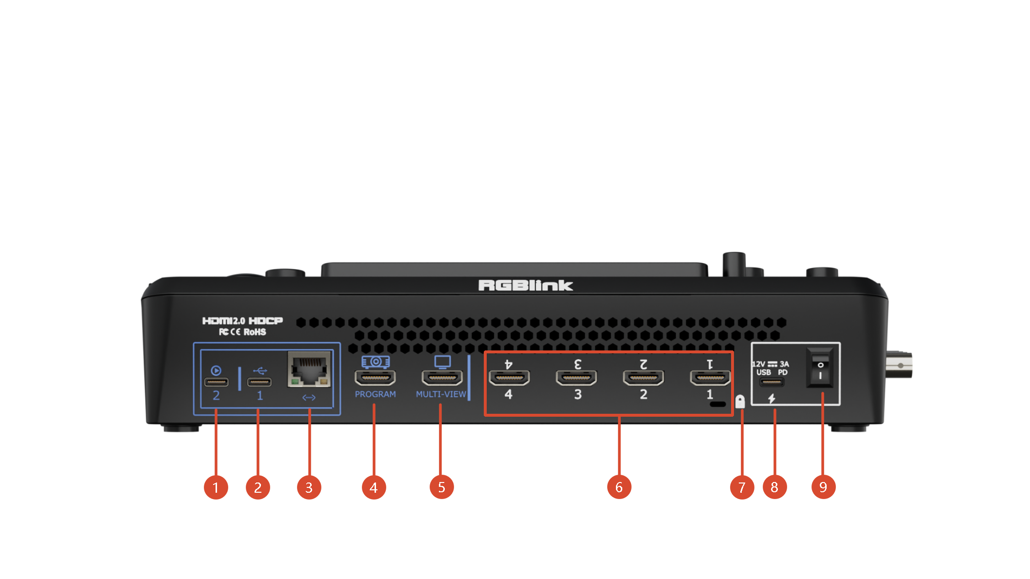
No.PortDescription
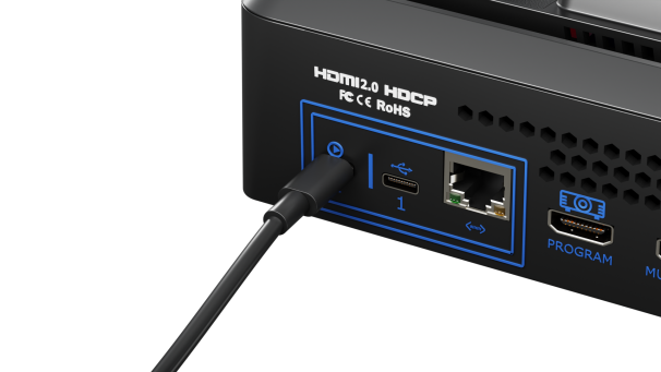
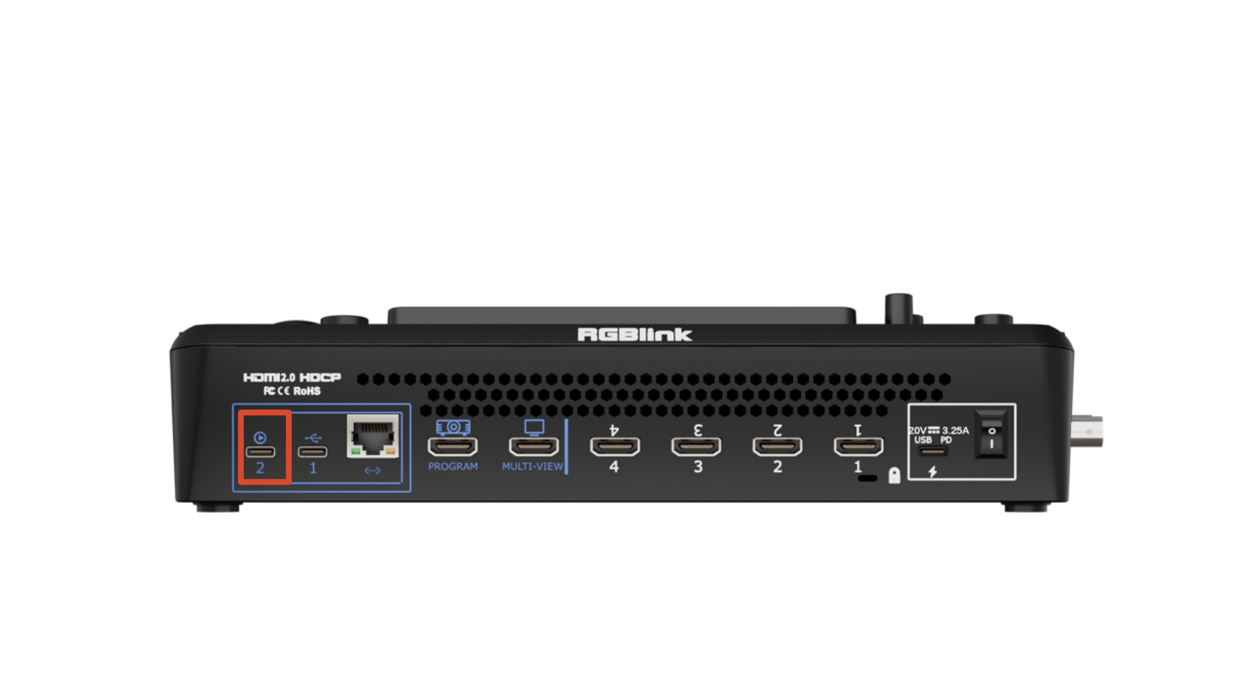
โถUSB-C 2Connected to a computer (via USB-C cable) or an Android device (via OTG cable). Recognized as a webcam by a third party software like OBS or zoom to capture and output the program view on air in applications like remote video conference.
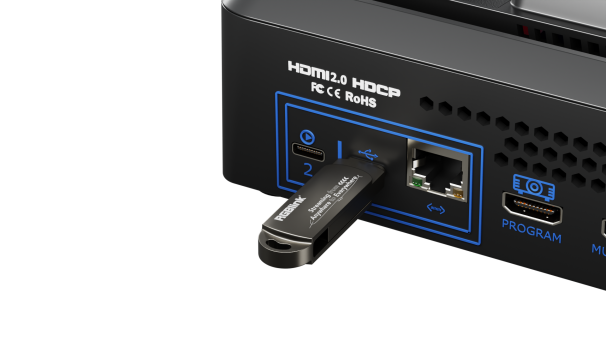
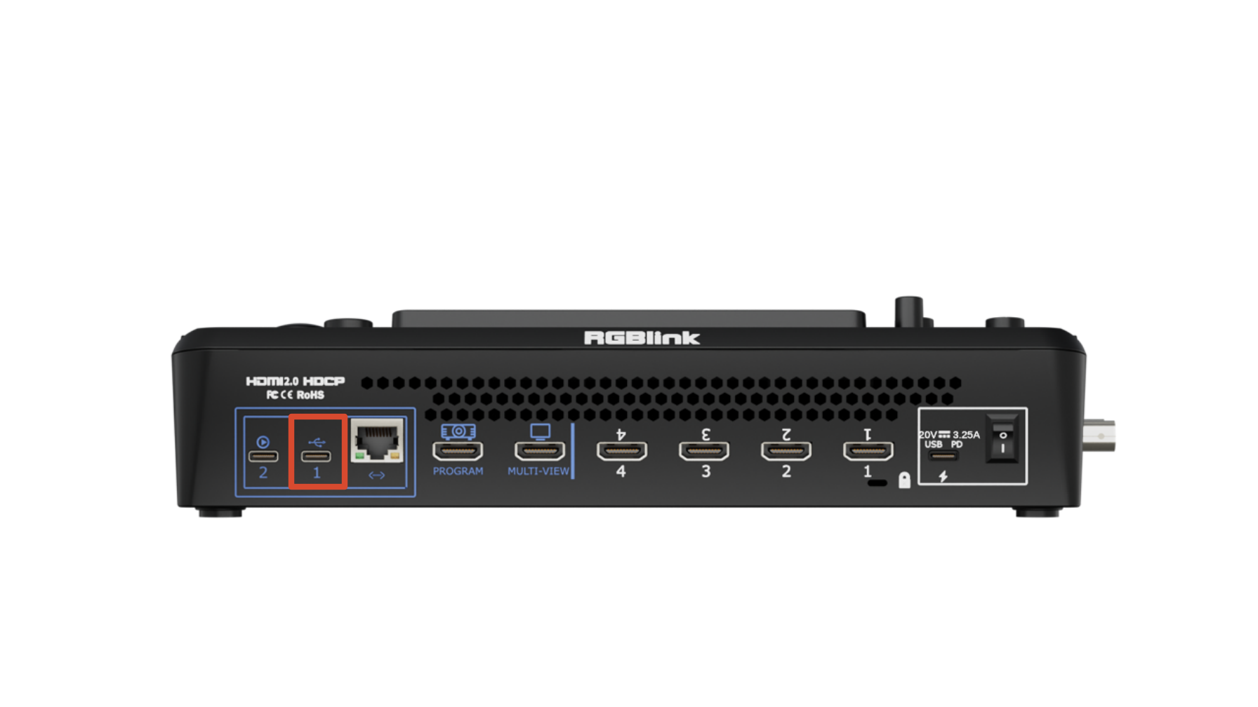
โทUSB-C 1[1]โ—‹ Connect to a USB camera as the fifth input signal (default function). โ—‹ Record the Program output view to a USB drive or SSD. โ—‹ Import audio, video, and image files from a USB drive.
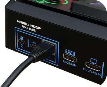
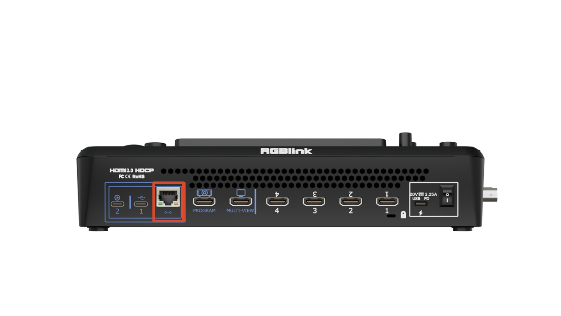
โธEthernet Portโ—‹ Streaming: Go live over the internet without a computer. โ—‹ Remote PTZ control via IP VISCA for IP workflow.
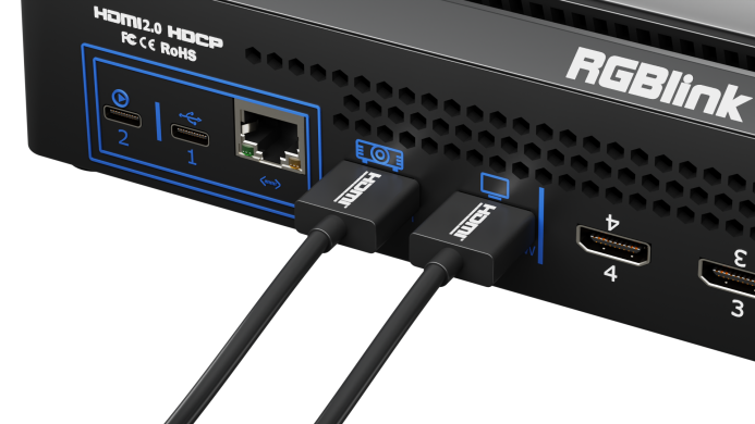
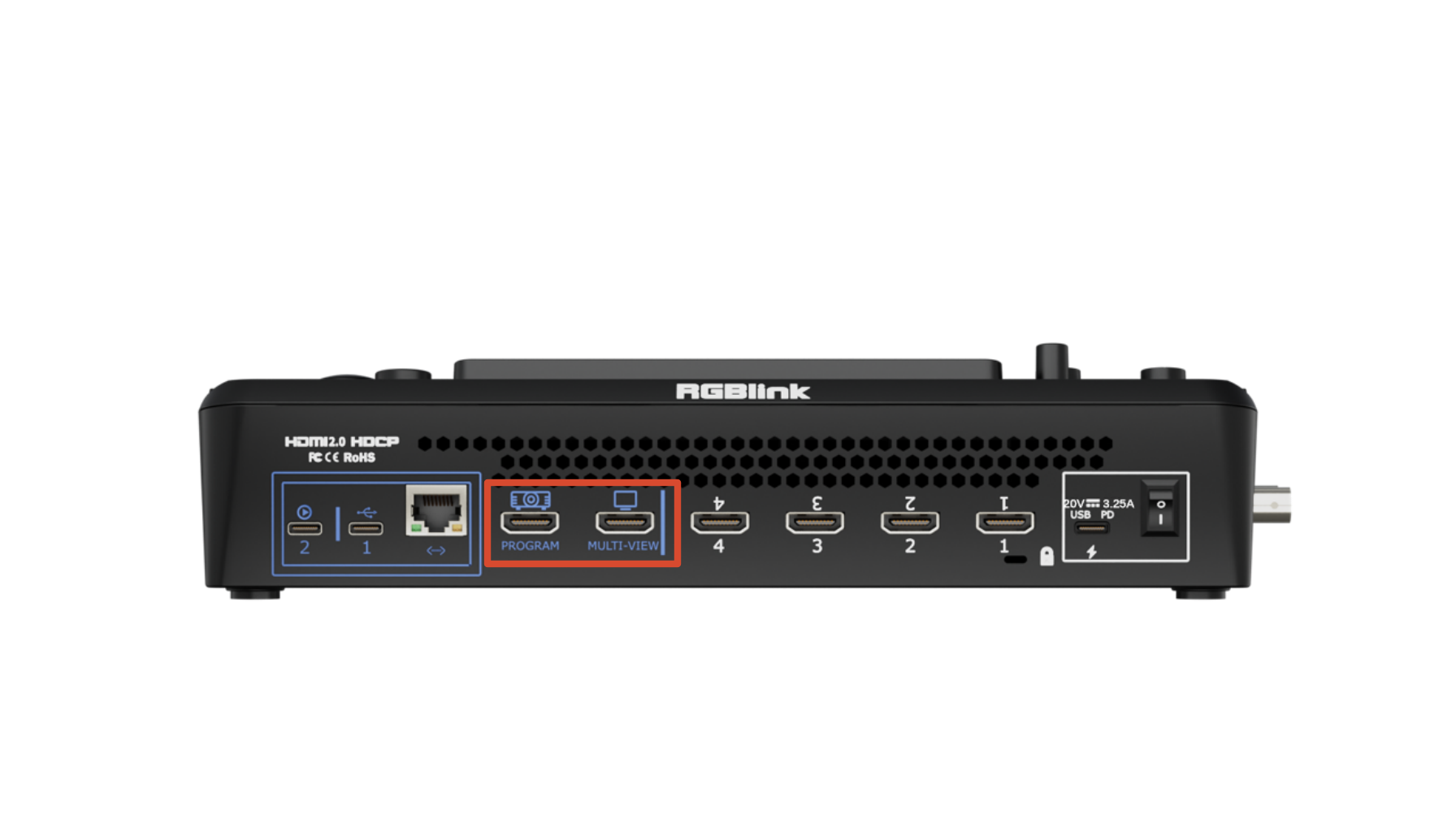
โนPROGRAM OutputBy default, it outputs the program feed but can be switched to output test color bars.
โบMULTI-VIEW OutputWhen connected to a display, it monitors all input and output signals simultaneously in a multi-view layout.
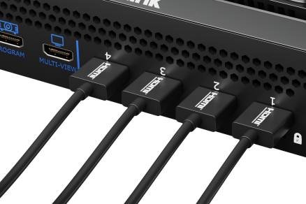
โปHDMI 1-4 INโ—‹ Four HDMI input channels for connecting HDMI sources. โ—‹ 4K60 resolution and downward compatible with all resolutions.
โผLocking HoleUse the T-lock to fix the device.
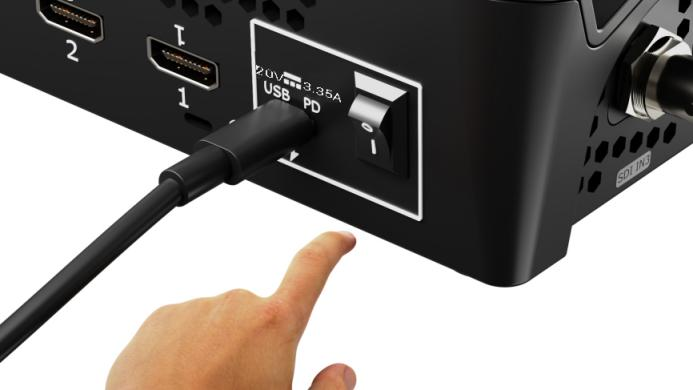
โฝUSB-C Power SocketPD protocol support, 20V 3A.
โพPower SwitchBoat-shaped switch. Press downward to turn on the switch.
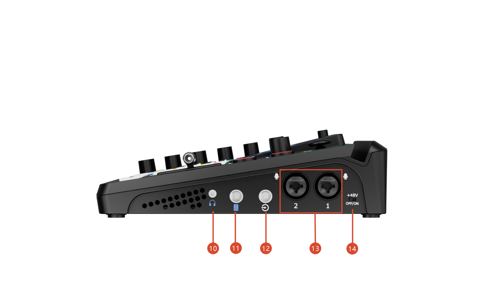
โฟHeadphone Output3.5mm mini-jack for audio monitoring.
โ“ซ6.35mm TRS JackBalanced TRS audio output.
โ“ฌLine-inBalanced 6.35mm TRS jack to connect to PC, mobile phone, or audio console.
โ“ญMIC inโ—‹ XLR+TS input port to connect to microphone. โ—‹ 48V Phantom Power supported.
โ“ฎ+48VPhantom Power Switch [2]โ—‹ Default to OFF for safety. โ—‹ Manually enable it when connecting a condenser microphone that requires 48V phantom power.
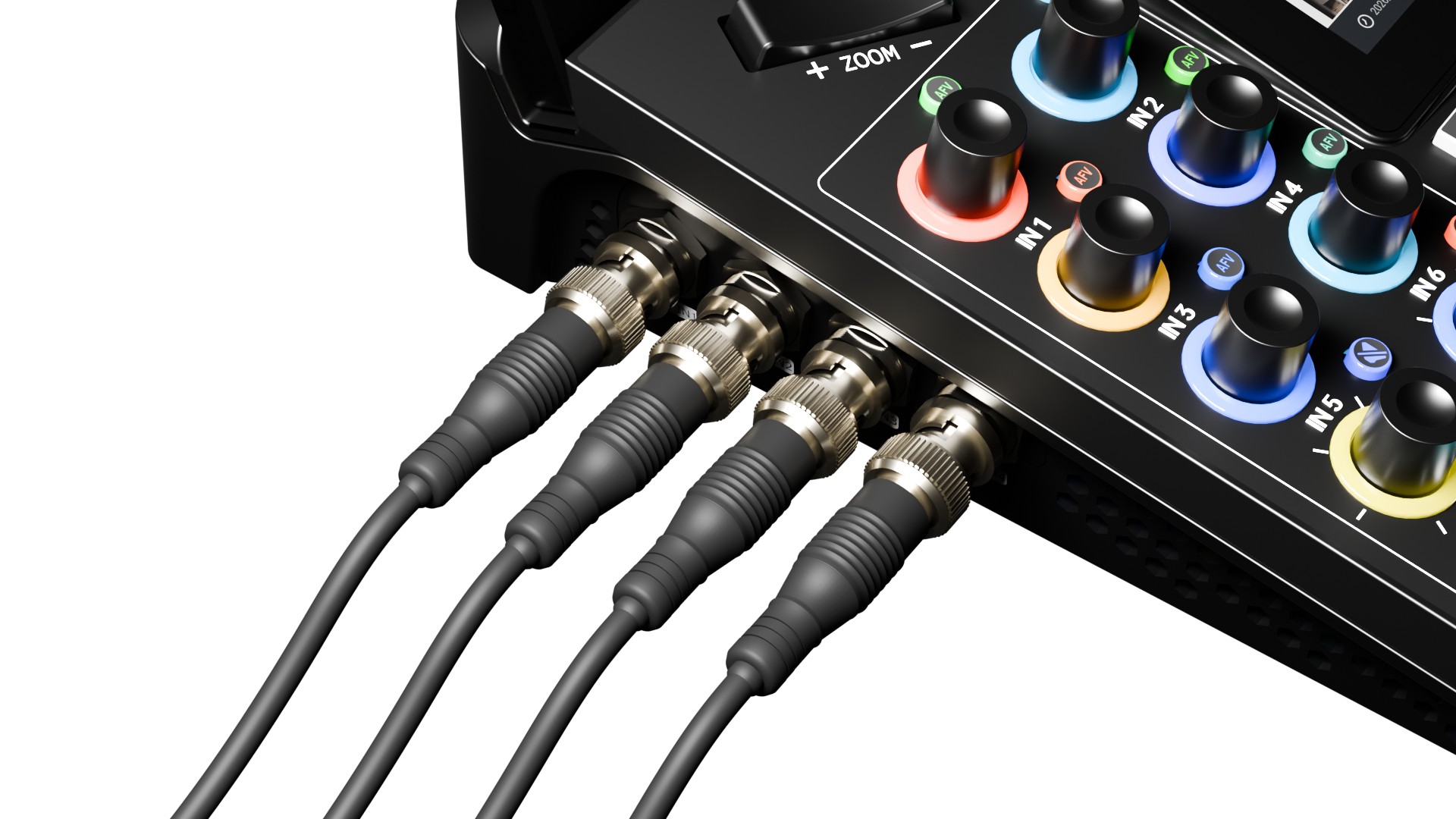
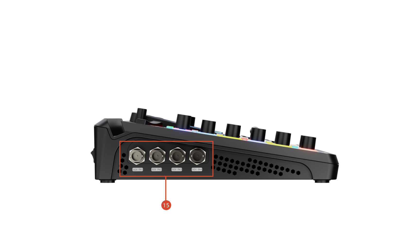
โ“ฏSDI 1-4 Inputsโ—‹ Four 12G-SDI input ports can be connected to UHD cameras and other input sources. โ—‹ 12G SDI compatible with 6G/3G/HD/SD-SDI.
๐Ÿšจ  Hot-Plugging Warning

48V phantom power supplies operating voltage to condenser microphones through the XLR input.

Do not connect or disconnect microphones or XLR cables while 48V phantom power is enabled.

When phantom power is turned on, voltage is present on the XLR connector. Connecting or disconnecting cables under power may generate current surges that can result inloud pops or unwanted noise,microphone malfunctionordamage to the audio circuitry of the device or connected equipment.


๐Ÿ“ข  Notes

[1] The two USB-C ports are functionally independent. The functions available on one USB-C port cannot be accessed through the other port via a USB hub, docking station, or adapter.  

[2] Phantom power should be enabled only when using a condenser microphone that requires external power. Disable phantom power before connecting other audio devices.


๐Ÿ“ข  Compatibility Notice

Only H.264-encoded UVC cameras are supported for โท UVC input.

Compatibility may vary between UVC camera models and manufacturers. If a connected camera cannot be detected or does not function properly, please contact RGBlink Technical Support.

2.2Use Your Product

Get started with the key steps for using your product.

2.2.1Version Check & Update

Connect the device to the network before use to ensure access to the latest system updates.

Network Connection

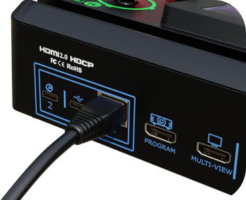
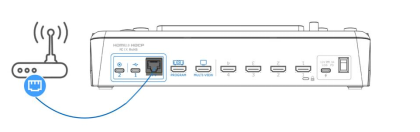
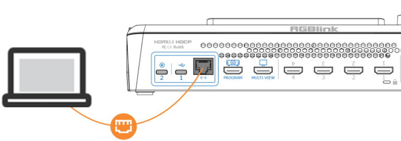
Connect the mini-extreme ISO Ethernet port to a router using a CAT6 Ethernet cable.

๐Ÿ‘‰

If DHCP is enabled on the router:

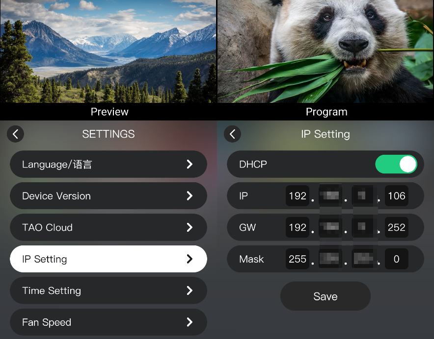
  1. Press MENU.
  2. Go to SETTINGS > IP Setting.
  3. Enable DHCP. The device automatically obtains an IP address.

System Update

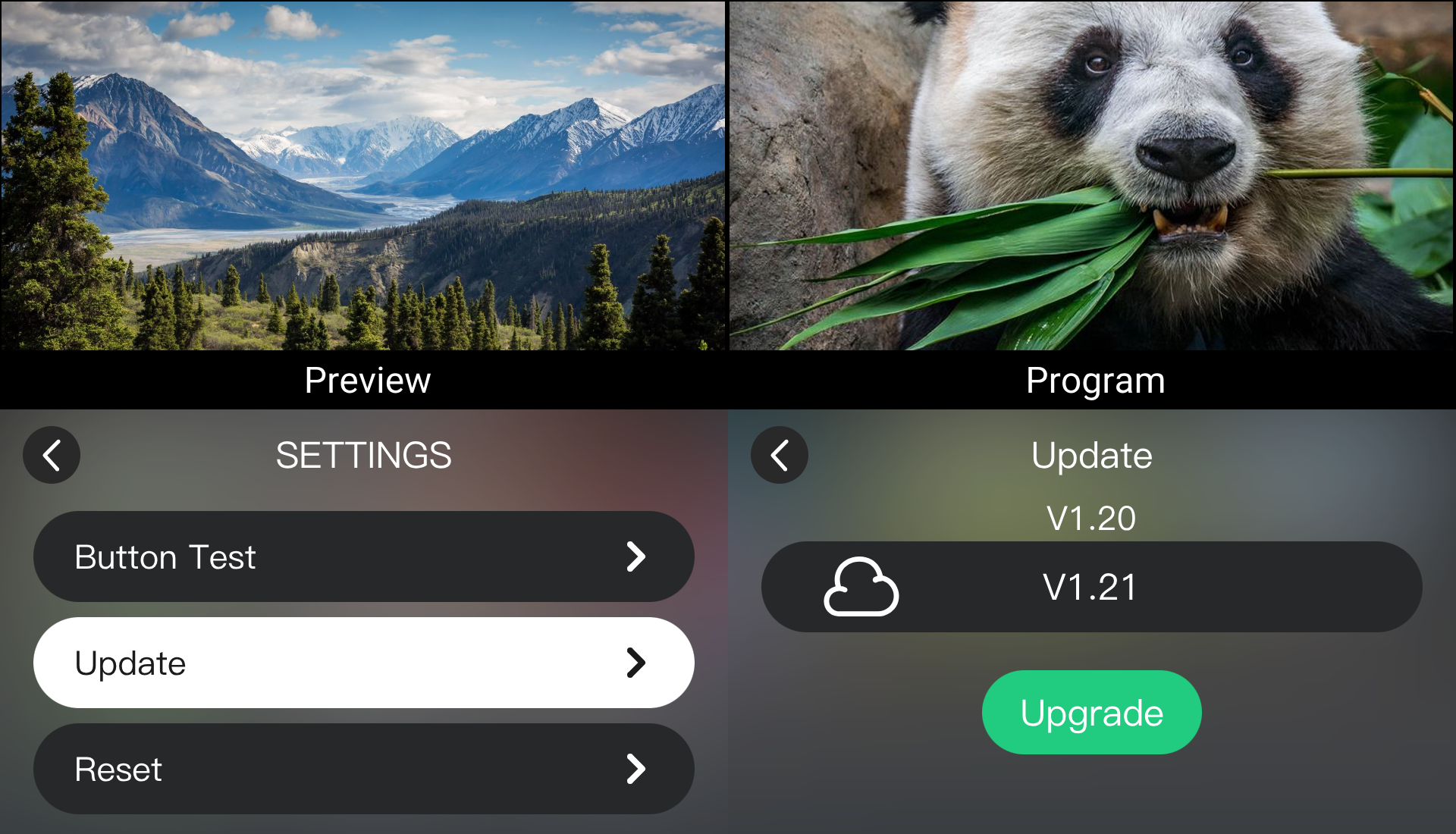
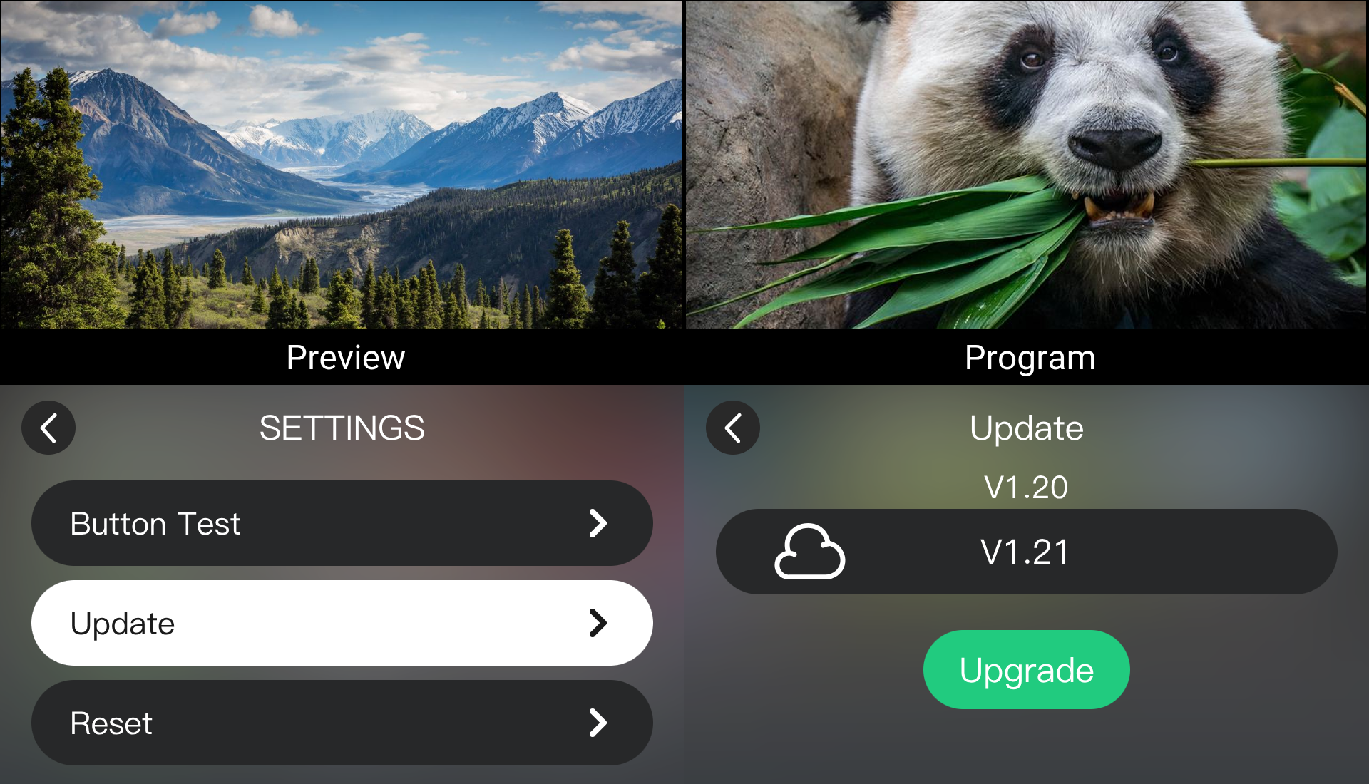
  1. Press MENU.
  2. Go to SETTINGS > Update.
  3. Check the firmware version.
  4. If an update is available, follow the on-screen instructions to update the device.

2.2.2Operation

Buttons and Touchscreen

mini-extreme ISO combines physical buttons with a touchscreen. See chapter Front Panel for details.

Remote Operation

mini-extreme ISO supports remote control via the Web App and TAO Cloud.

See chapter Version Check & Update and complete the network connection and update steps first.

Web App

On mini-extreme ISO:

  1. Press MENU.
  2. Go to SETTINGS > IP Setting.
  3. Enable DHCP to obtain an IP address.

On a computer on the same LAN:

  1. Open a browser and enter the device IP address.
  2. Press Enter.
  3. The Web App opens. Use it to switch signals, configure the device, and perform other remote operations.

TAO Cloud

  1. Press MENU.
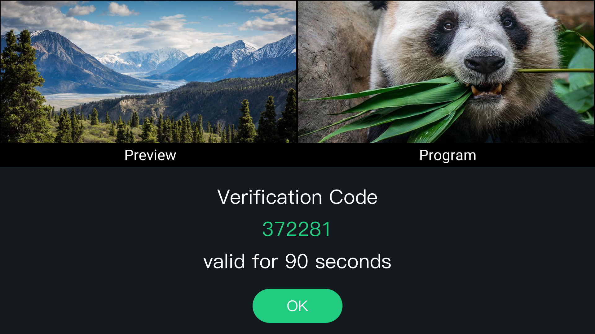
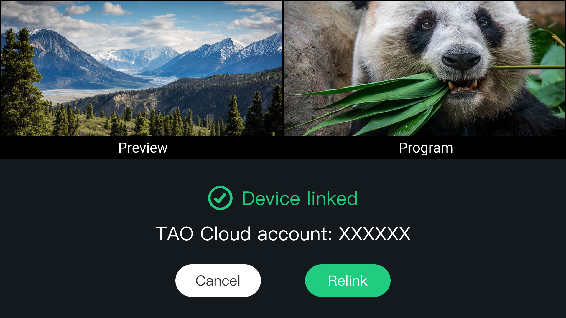
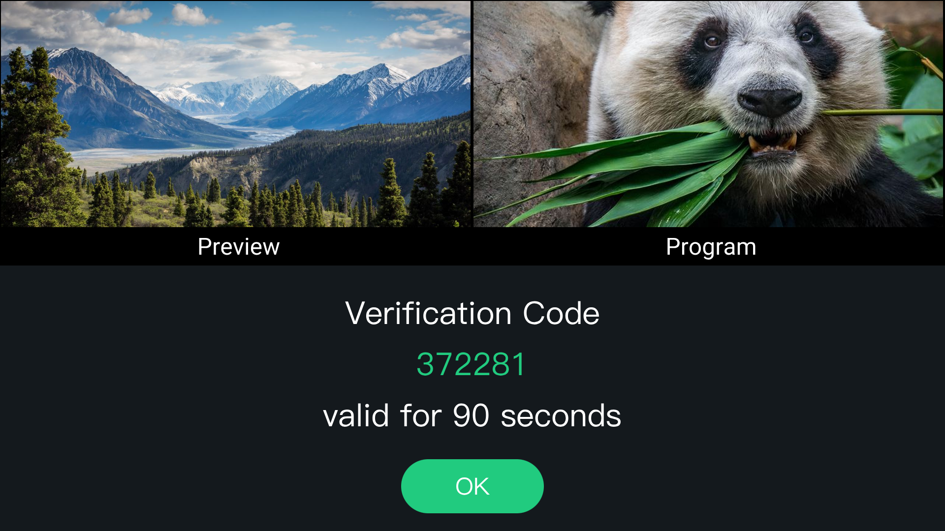
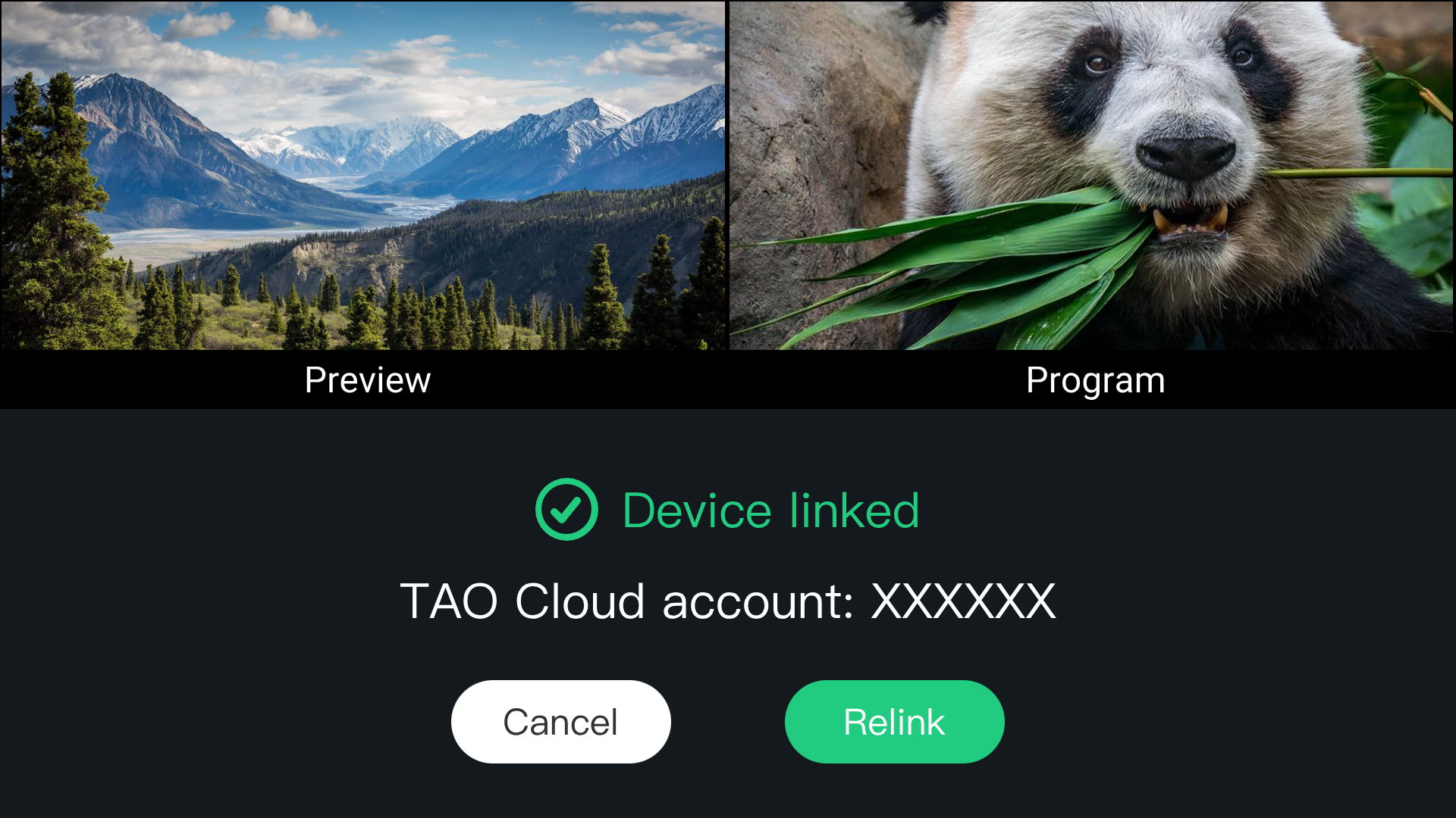
  2. Go to SETTINGS > TAO Cloud to get the binding code.
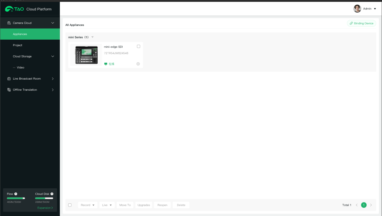
  3. Visit TAO and sign in. Bind mini-extreme ISO to manage it through TAO Cloud.

See chapter TAO Cloud for details.

2.2.3TAO Cloud

Get the Binding Code

See chapter Version Check & Update and complete the network connection first.

Press MENU and go to SETTINGS > TAO Cloud.

If mini-extreme ISO is not bound to TAO Cloud, use the displayed code to bind the device.

Sign In or Register for TAO Cloud

Enter the TAO Cloud URL in a browser to open the sign-in page.

Enter your e-mail and verification code, then click Sign Up / Register.

TAO Cloud: https://www.tao1live.com

Bind the Device

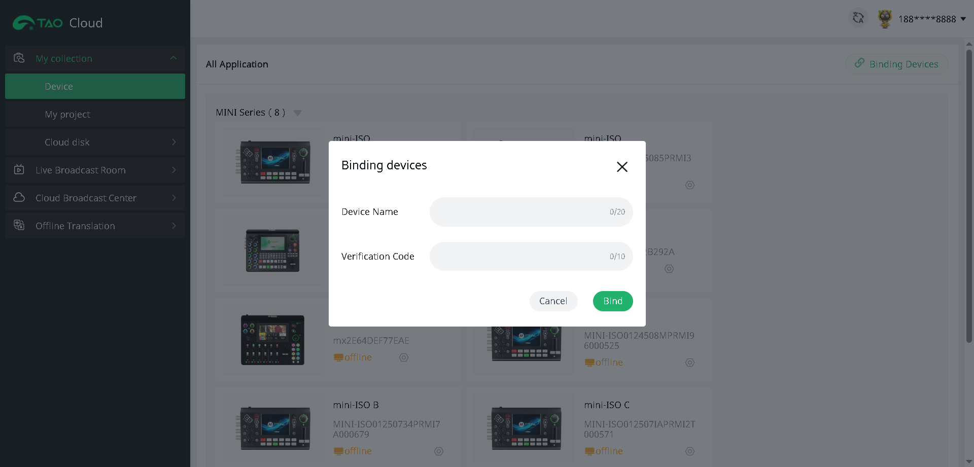
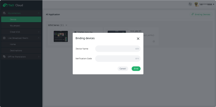
In TAO Cloud, go to My Collection > Device > Binding Devices.

Enter a device name and the verification code in the pop-up window, then click Bind.

View the status of bound devices under All Application.

Unbind the Device

Tap TAO Cloud again and select Rebind to unbind the device.

2.2.4Input Settings

Select Input Sources

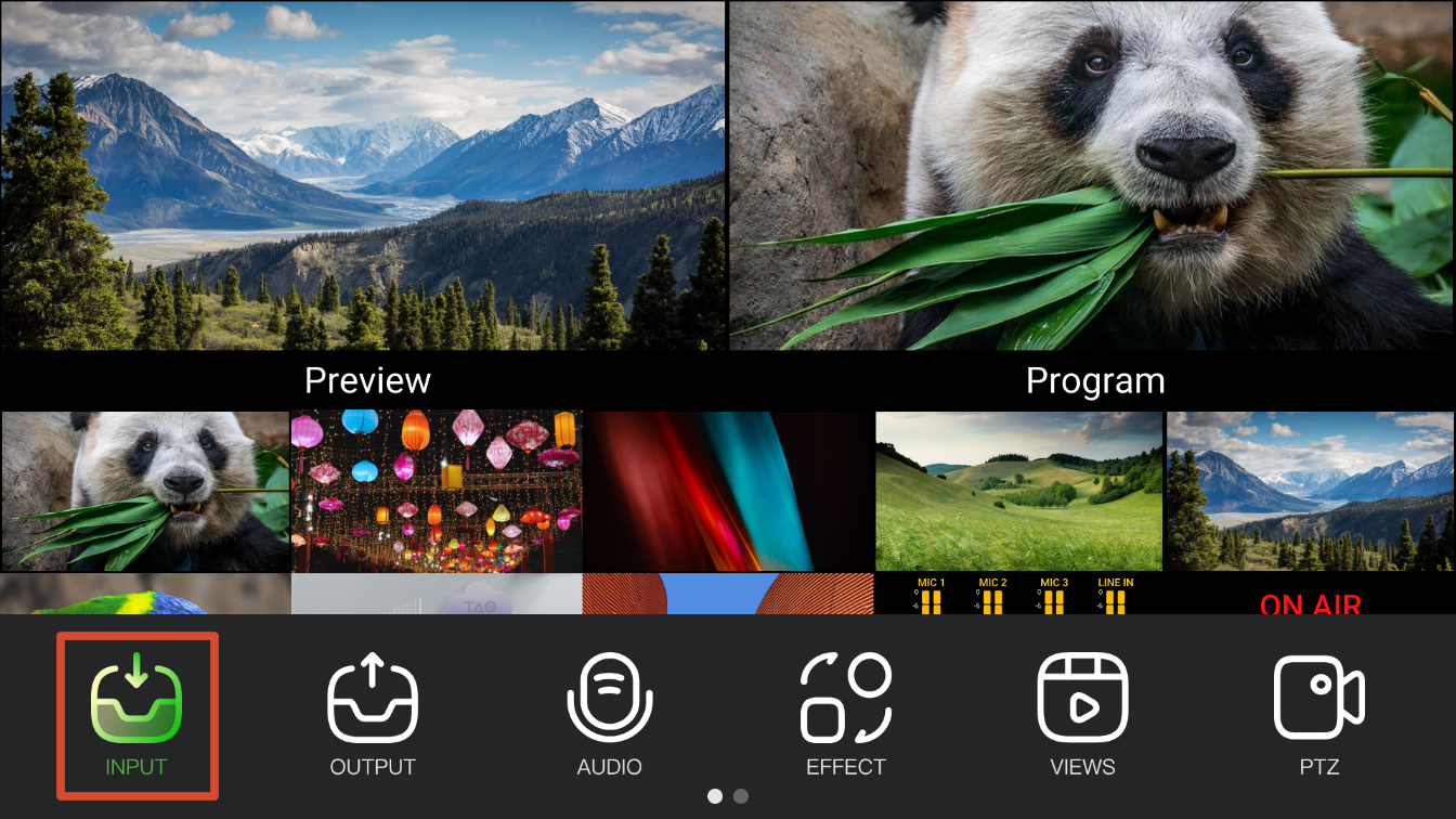
Press MENU and go to INPUT to assign sources to IN1โ€“IN8.

InputSource
IN1โ€“IN4HDMI 1โ€“4; EDID management supported
IN5SDI 1 or SDI 2
IN6SDI 3 or SDI 4
IN7โ€“IN8UVC camera or NDI stream

Input Windows

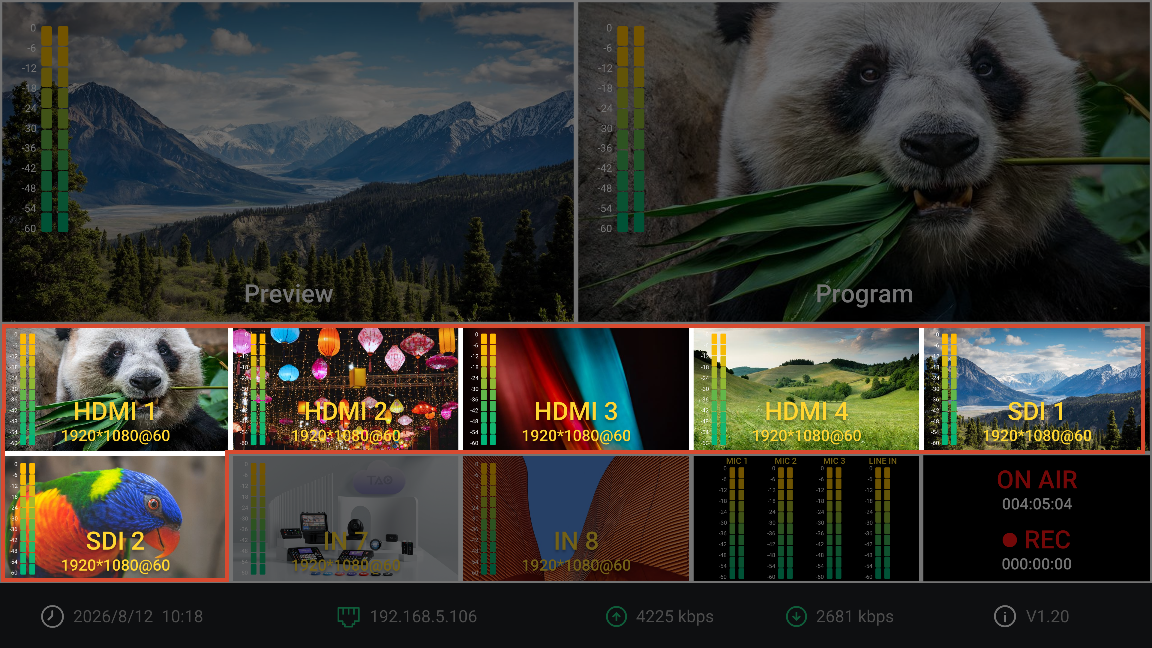
IN1โ€“IN8 correspond to the preview windows on the main screen.

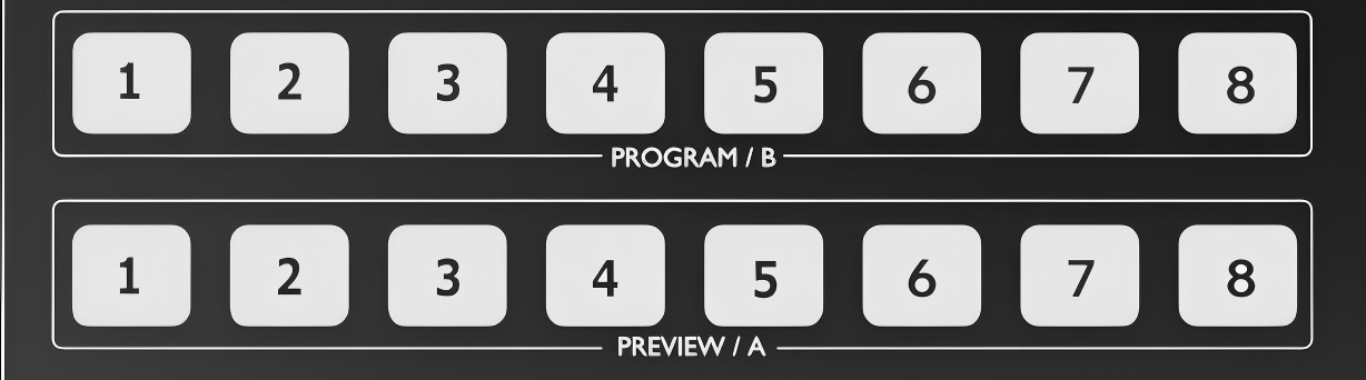
Use the number buttons 1โ€“8 in the PROGRAM/B and PREVIEW/A rows on the front panel to route the corresponding source to Program or Preview.

๐Ÿ‘‰

2.2.5Import Materials

Press MENU and go to INPUT to set the foreground and background assets.

  1. On a USB drive, create the following folders and add the corresponding assets:
    • mini-extreme/background
    • mini-extreme/foreground
  2. Connect the USB drive to USB-C 1.
  3. When the USB drive is detected, the RECORD indicator lights up.
  4. Go to INPUT > BACKGROUND or FOREGROUND to open the asset menu. Select and enable an asset from the USB drive.

2.2.6Signal Layout

mini-extreme ISO supports displaying Layer A and Layer B in both Preview and Program. Layer A is the main picture; Layer B is the secondary picture.

Select Layer A/B

Example: Select Layer B.

  1. Press B. The indicator lights solid blue.
  2. Press an input button in the PROGRAM/B row to assign a source to Layer B.
  3. The assigned input button lights solid blue.

Set the PIP Layout

mini-extreme ISO provides 7 PIP layouts. Select a layout, then adjust the size and position of Layers A and B.

  1. Select a PIP layout.
  2. Press A or B to edit the corresponding layer.
  3. Turn the ZOOM control to adjust the layer size.
  4. Move the 5-Direction Joystick to adjust the layer position.

Apply Chroma Key to Layer B

Chroma key is applied to Layer B by default.

  1. Press B. The indicator lights solid blue.
  2. Press the Chroma Key button in the PIP row.
  3. Go to Chroma Key and enable the color picker. Adjust the chroma key settings.

Save and Recall a Scene

Save the current layer and layout settings as a scene.

  1. Press and hold any unlit button in the VIEWS row, or save the current settings from the Scene menu.
  2. Press the corresponding saved scene button to recall the scene.

2.2.7Signal Switching

Transition Modes

mini-extreme ISO supports four transition modes: CUT, AUTO, FTB, and T-Bar.

The default transition is 1.0 s MIX.

  1. CUT: Instant transition with no effect.
  2. AUTO: Applies the selected transition effect and duration.
  3. FTB (Fade to Black): Fades the output to black.
  4. T-Bar: Manually controls the transition speed.

Transition Effects

The front panel provides shortcut buttons for transition effects and duration.

More effects are available under MENU > EFFECT.

2.2.8PTZ Control

mini-extreme ISO supports simultaneous control of up to 8 PTZ cameras via IP VISCA.

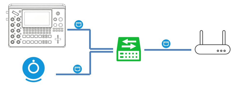
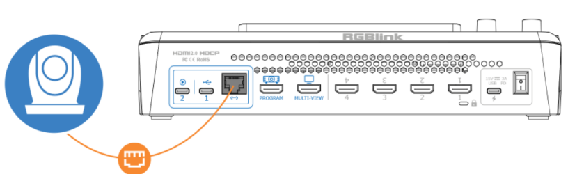
PoE cameras are recommended. Use an Ethernet cable for connection. Use a network switch for multiple cameras.

Set Up the Network

mini-extreme ISO and the PTZ cameras must be on the same subnet.

For a network with subnet mask 255.255.255.0, the first three IP address segments must match. The last segment must be 2โ€“254 and unique for each device.

Example: 192.168.1.2, 192.168.1.3, 192.168.1.4

  1. Go to SETTINGS > IP Setting.
  2. Enable DHCP to obtain an IP address automatically.
  3. Disable DHCP and use the ENTER knob to set a static IP address.
๐Ÿ“ข  Notes

Connect multiple PTZ cameras through a network switch. Assign a unique IP address to each device to avoid IP conflicts.

Configure PTZ Cameras

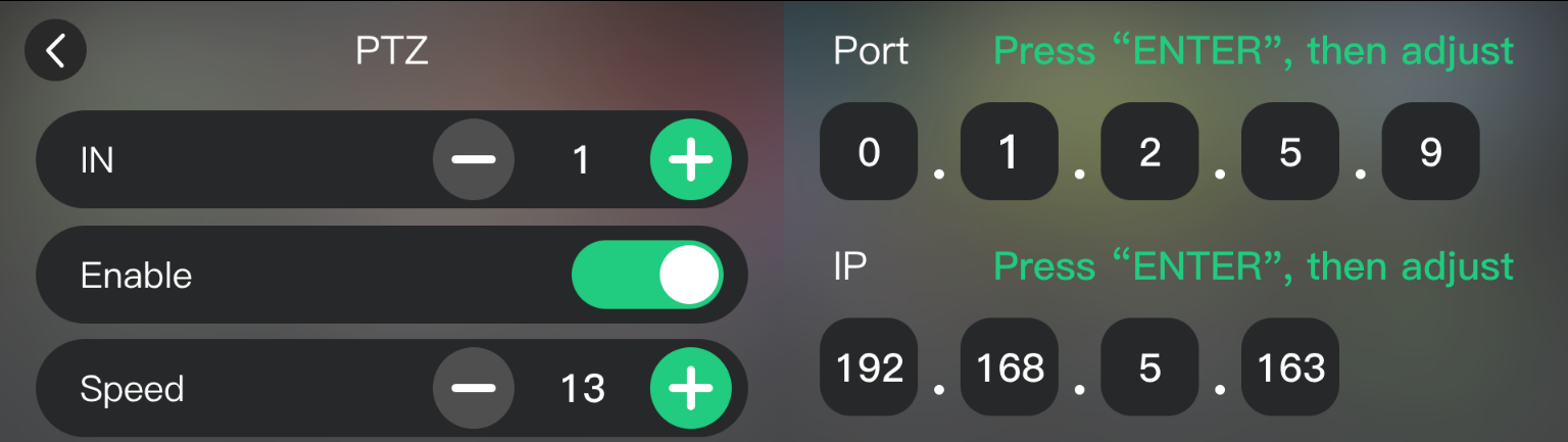
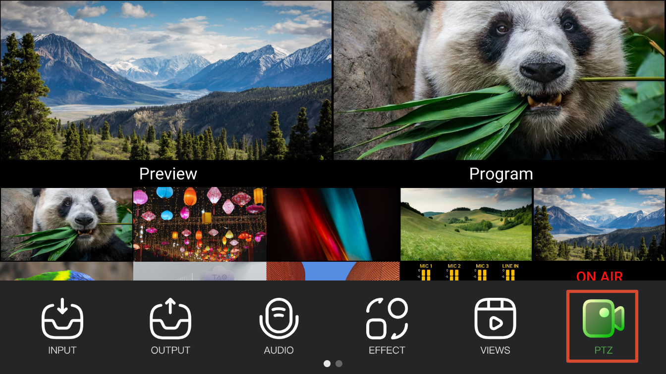
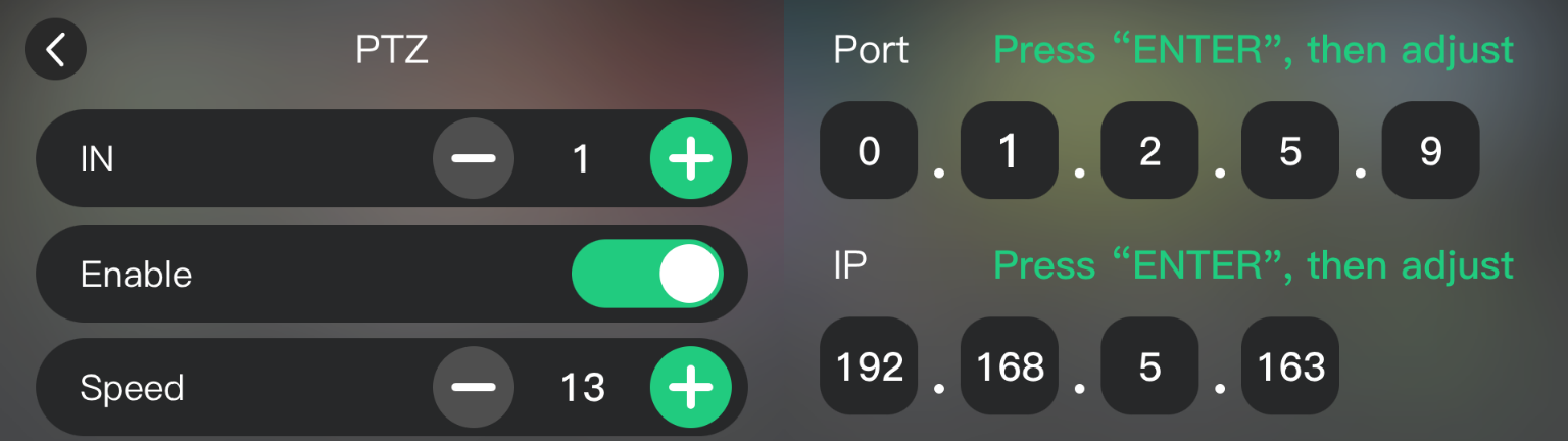
Set the IP address and port for each camera on page 2 of the PTZ menu.

  1. Connect the PTZ camera to mini-extreme ISO or a network switch.
  2. Go to page 2 of the PTZ menu.
  3. Press + or - to select a PTZ camera.
  4. Set the camera IP address and port as prompted.
  5. Tap Enable to receive the camera feed.

๐Ÿ“ข  Notes

RGBlink vue series broadcast cameras are recommended. Their default port is `1259`. 

For other camera brands, check the camera manual for the correct port.

Control PTZ Cameras

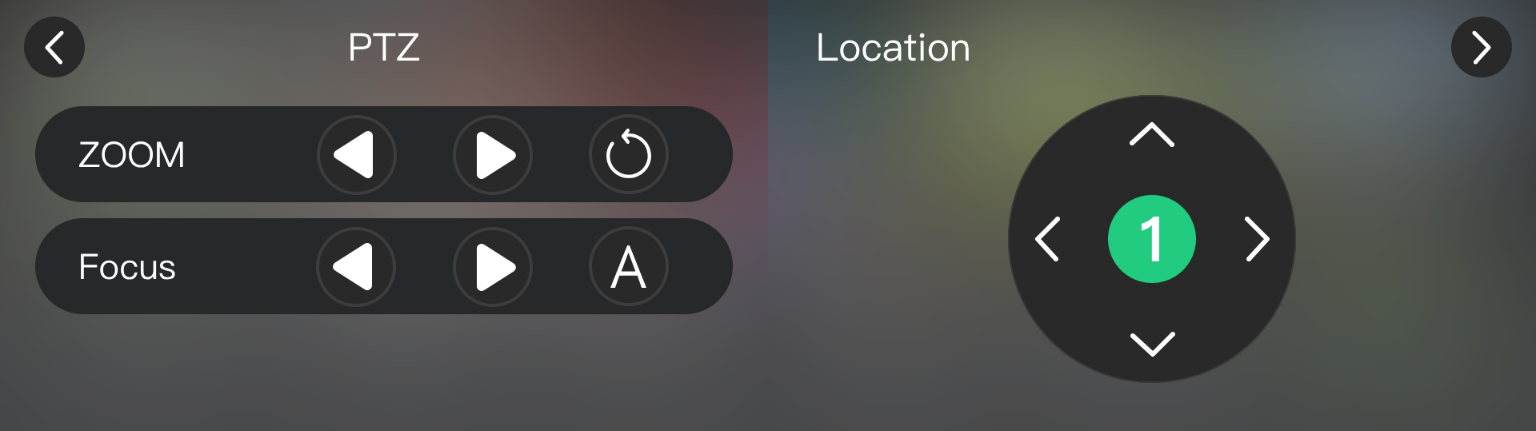
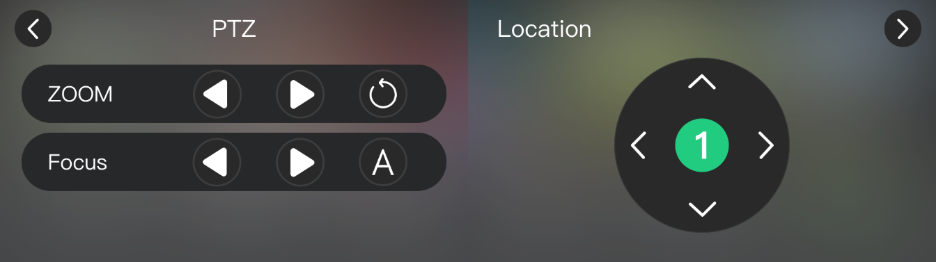
mini-extreme ISO supports camera zoom, focus, pan/tilt, and speed control.

  1. Assign the target PTZ camera to Preview.
  2. Use the ZOOM control to adjust zoom.
  3. Use the FOCUS knob to adjust focus.
  4. Go to PTZ to adjust zoom, focus, pan/tilt, and speed.

Save PTZ Presets

Save the current PTZ settings as part of a view.

  1. Assign the target PTZ camera to Preview.
  2. Adjust the pan/tilt position, zoom, and other parameters.
  3. Save the current settings as a view.
  4. Recall the view to restore the saved PTZ settings.

2.2.9Output Settings

Multiview and Program Outputs

mini-extreme ISO provides two video outputs:

  • MULTI-VIEW: Outputs a 2K multiview.
  • PROGRAM: Outputs the 4K PGM or a selected input source.
MULTI-VIEWPROGRAM

Set Program Output Resolution

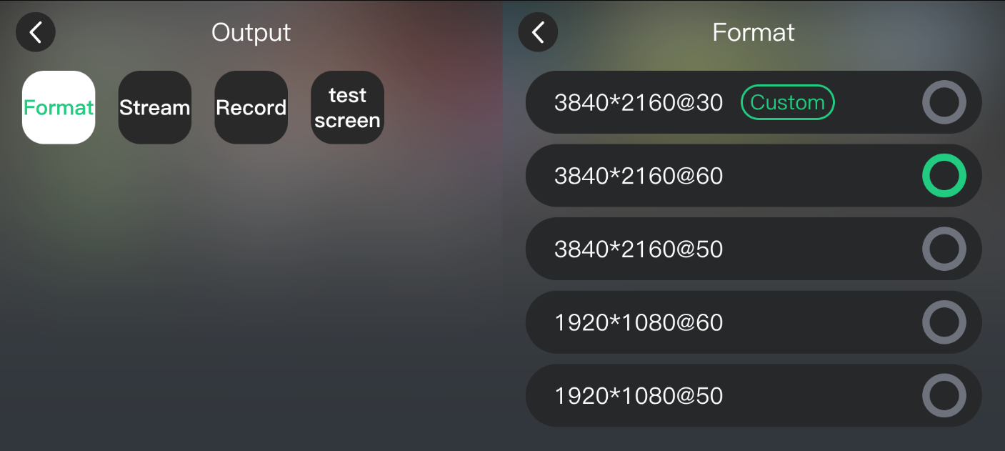
The maximum program output resolution is 3840ร—2160@60Hz.

  1. Go to OUTPUT > Format.
  2. Select the required output resolution.

Test Pattern

  1. Go to OUTPUT > test screen.
  2. Display the color bar test pattern.

2.2.10Recording

mini-extreme ISO supports recording the Program output to a USB drive or portable SSD.

๐Ÿšจ  Warning

Wait until the recording file is saved before removing the storage device. 

Otherwise, the file may be corrupted or fail to save.

Storage Detection and Recording

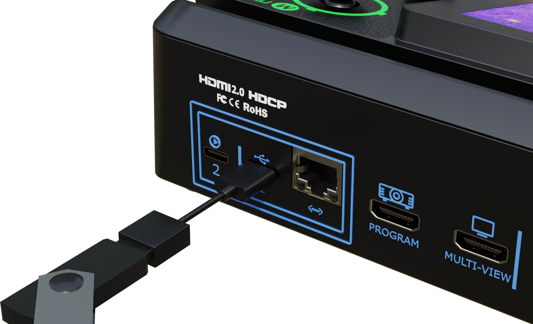
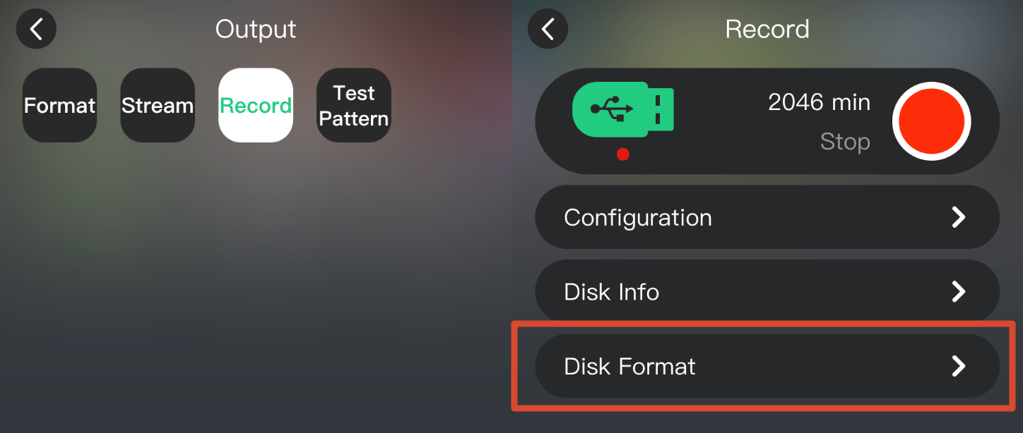
Connect a USB drive or portable SSD to USB 1 and wait for the device to detect it.

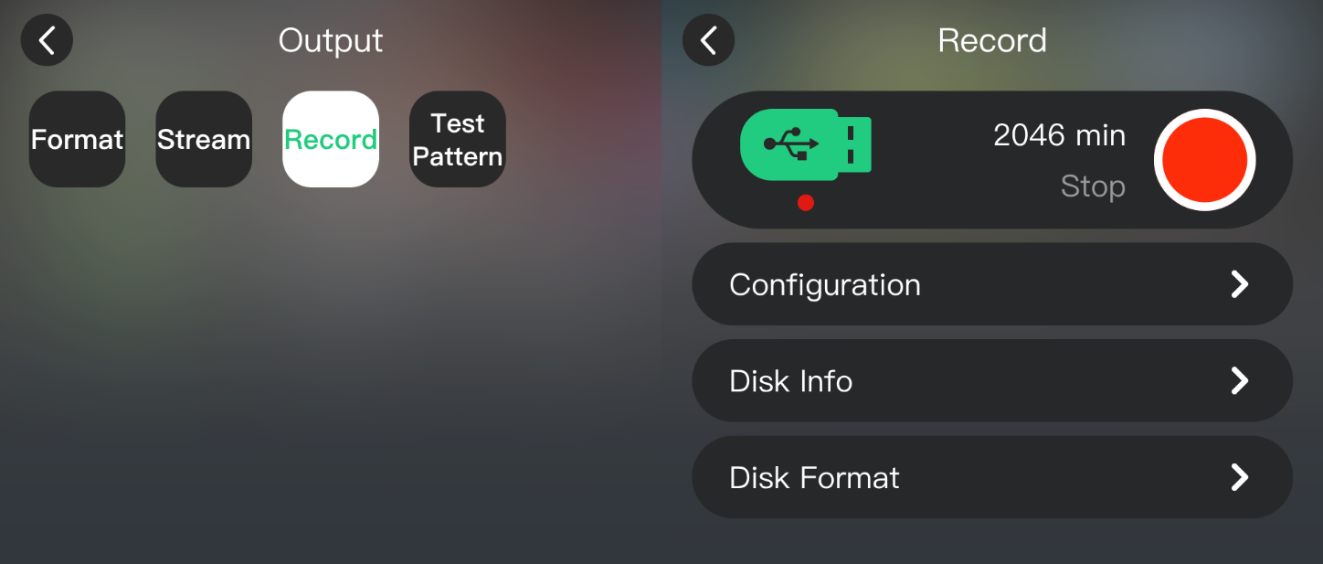
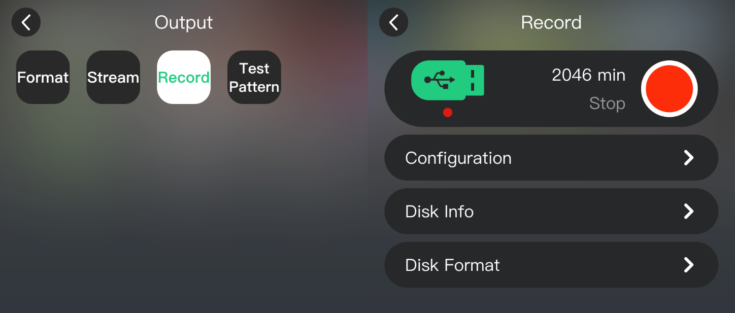
Go to OUTPUT > Record.

  1. Check the available recording time.
  2. Set the recording bitrate as needed.
  3. Tap the Record icon or press RECORD to start recording.
  4. Tap the Record icon or press RECORD again to stop recording.

๐Ÿ“ข  Notes

A higher bitrate provides better recording quality but requires more storage space.

Recording Modes

  • Program Recording: Records the 4K@60Hz Program output.
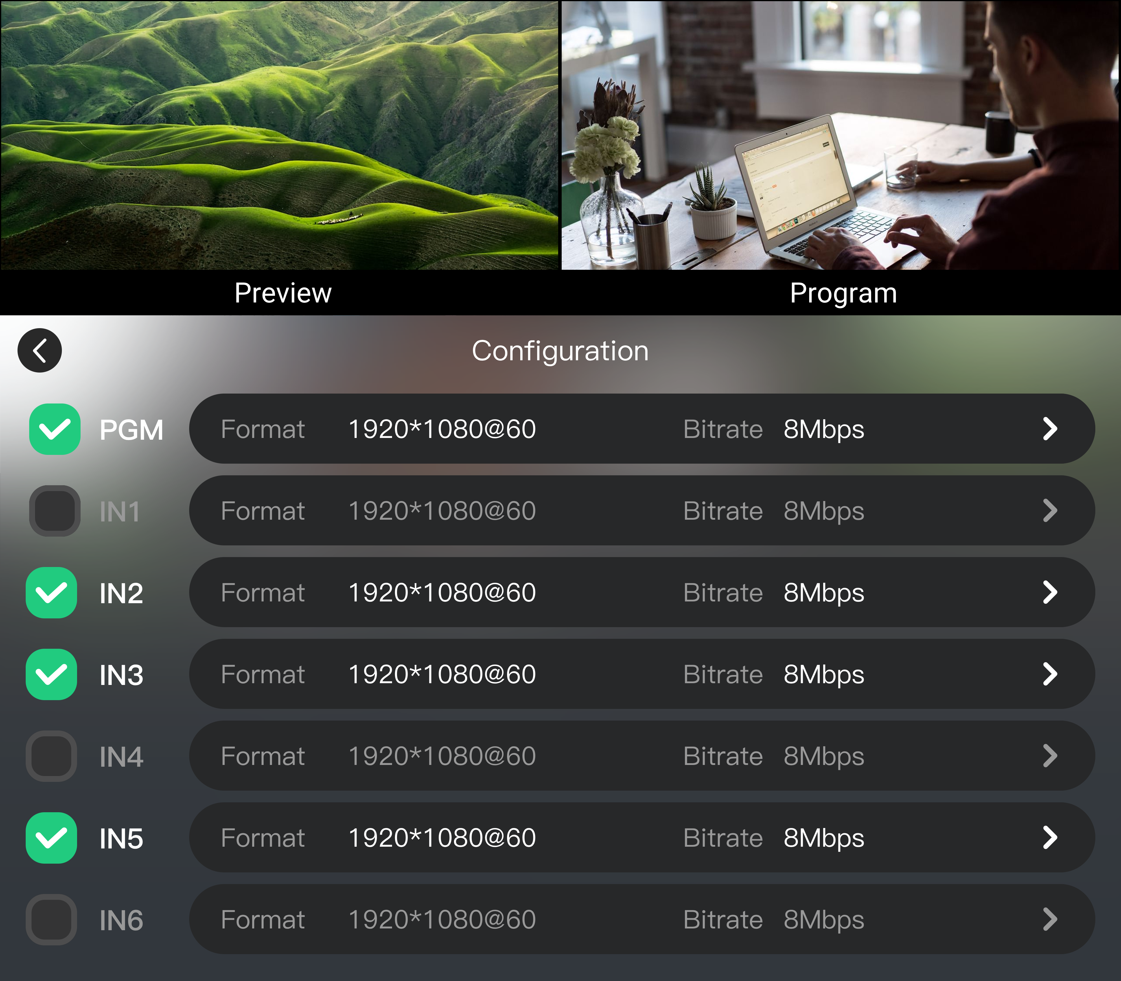
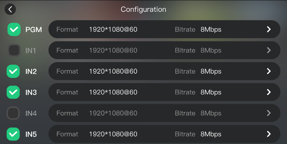
  • ISO Recording: Simultaneously records 1 Program output and up to 3 other input sources. Configure ISO recording under Configuration.

Recording Files

Recording files are named with a timestamp.

If the device is offline or the time settings under Settings are incorrect, the timestamp may be inaccurate.

๐Ÿ“ข Notes

- Format the storage device as exFAT.
- If recording fails, format the storage device as exFAT and try again.

2.2.11Live Streaming

mini-extreme ISO supports video output via USB, network streaming, and NDI.

Before using network streaming or NDI, connect mini-extreme ISO to the network and bind it to TAO Cloud.

OBS Capture

Connect mini-extreme ISO to a computer via USB 2 and add it as a video capture device in OBS.

  1. Connect USB 2 on mini-extreme ISO to the computer.
  2. Open OBS.
  3. Add a video capture device.
  4. Select RGBlink USB3.0 Capture.

Network Streaming

Send a streaming URL from TAO Cloud to mini-extreme ISO, then start streaming on the device.

  1. Get the streaming URL and stream key from the target platform.
  2. Sign in to TAO and bind the device. See chapter TAO Cloud.
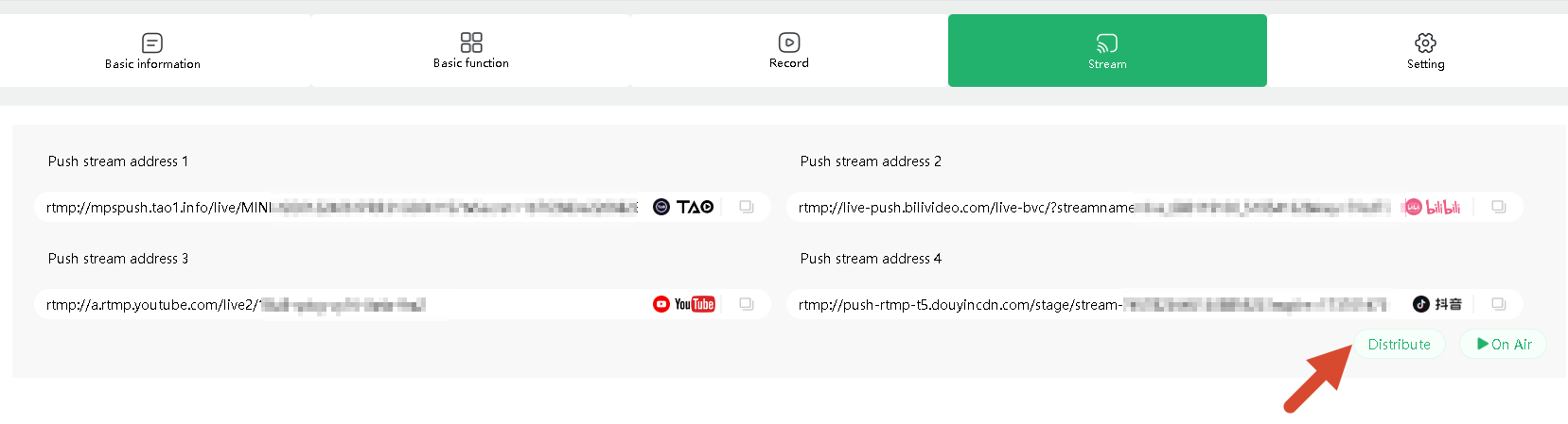
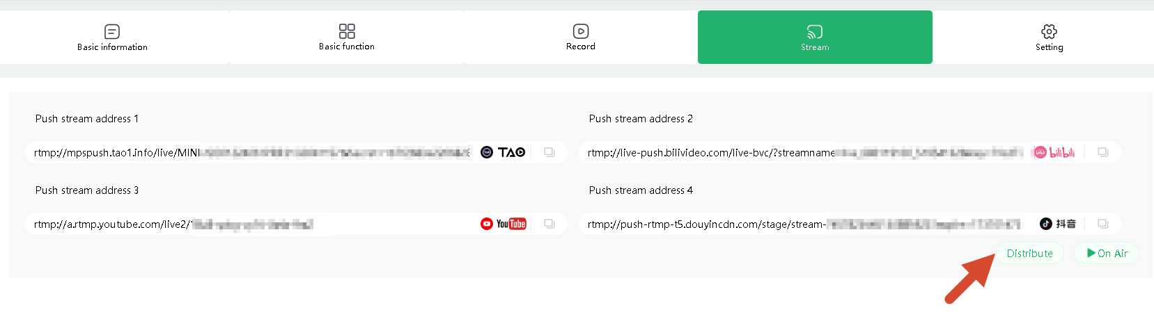
  3. Go to Device Management page > Stream.
  4. Enter the streaming URL and stream key.
  5. Click Distribute.

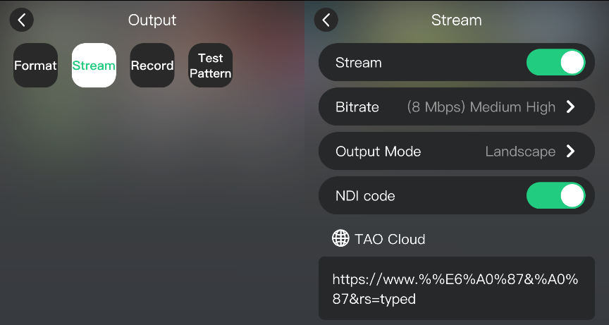
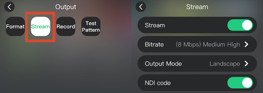
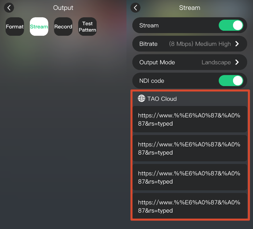
On mini-extreme ISO, go to OUTPUT > Stream and verify that the streaming URL has been received.

Start Streaming

After the streaming URL is received:

  1. Go to OUTPUT > Stream.
  2. Set the streaming bitrate and output mode.
  3. Select the target URL under TAO Cloud.
  4. Enable Stream, or press ON AIR on the front panel.

NDI Encoding

NDI encoding converts the video output to an NDI stream for transmission over the network.

  1. Sign in to TAO and bind the device. See chapter TAO Cloud.
  2. Go to Device Management page > Setting and authorize NDI.
  3. Enable NDI code under Stream on the device.

2.2.12Audio Settings

mini-extreme ISO supports 15 audio inputs, including embedded and external audio, with up to 11-channel audio mixing.

The front panel provides quick audio controls.

For detailed settings, go to MENU > AUDIO.

Embedded Audio

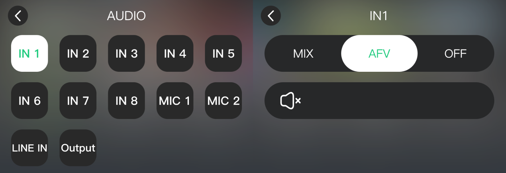
Set the audio mode for each input:

  • Mix: Adds the audio to the Program output.
  • AFV: Follows the video switch. Same as the front-panel AFV button.
  • Off: Disables the audio.

Microphone and Line Inputs

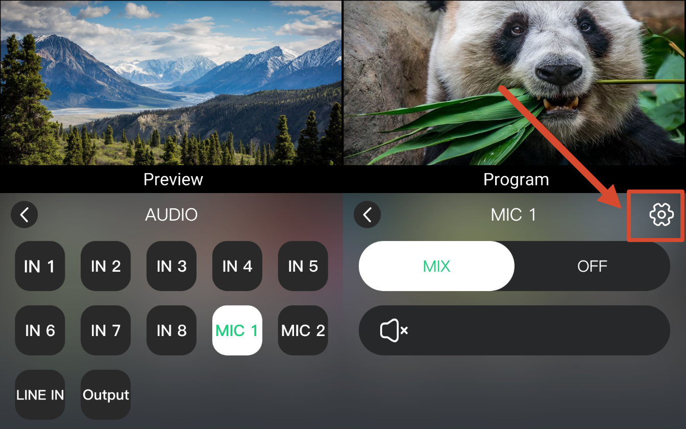
mini-extreme ISO supports MIC 1, MIC 2, and LINE IN.

  1. Select an audio source.
  2. Enable Mix to add it to the Program output.
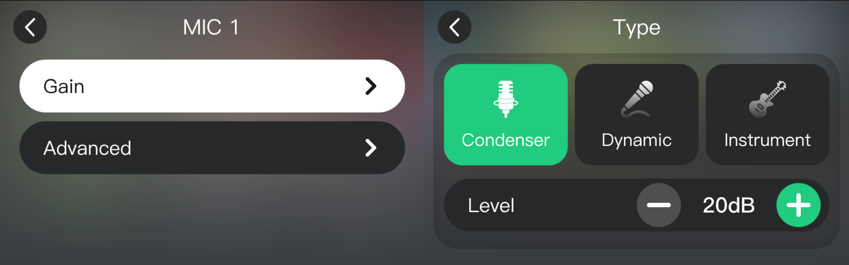
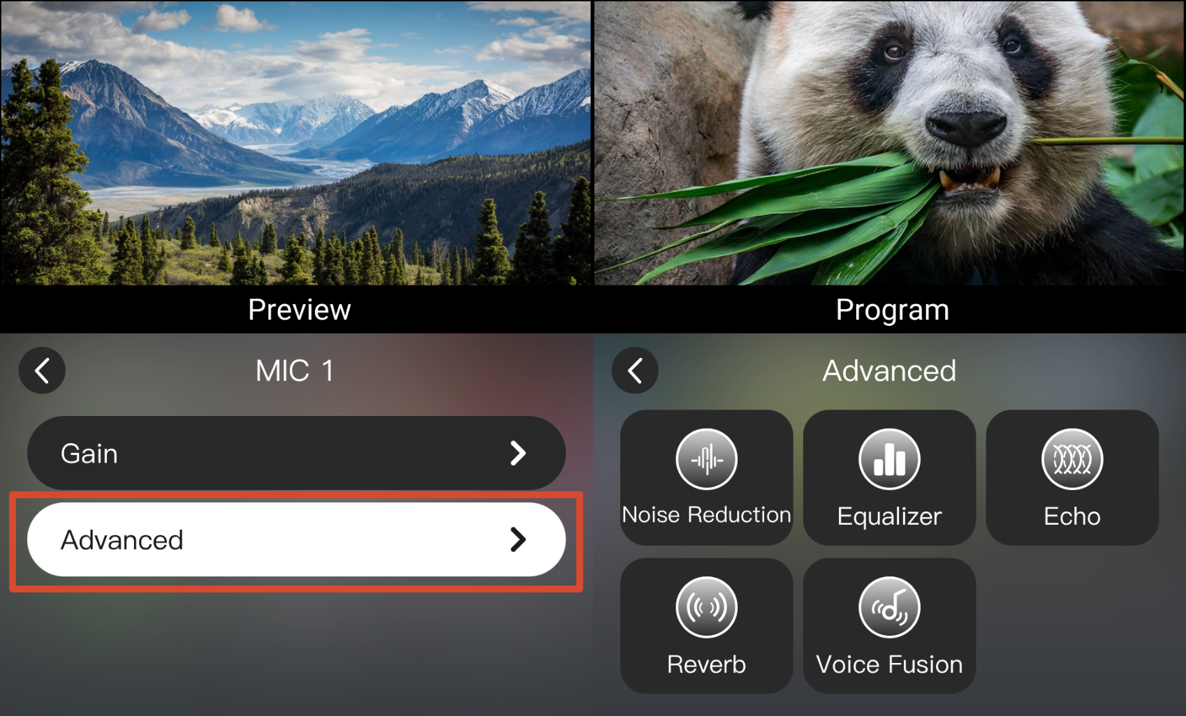
  3. Tap the settings icon โš™ in the upper-right corner. Adjust the gain and advanced settings such as EQ, echo, reverb, and so on.

Output Volume

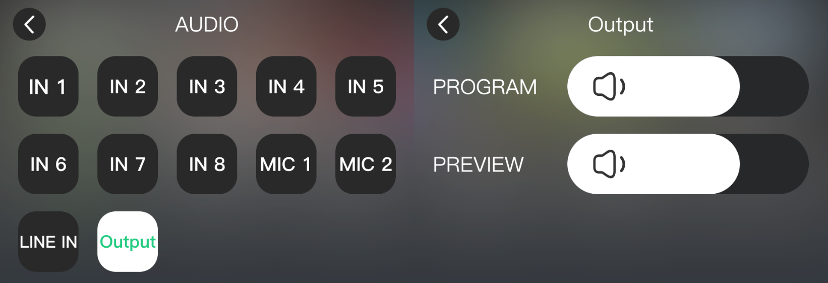
Adjust the Preview and Program output volume under Audio.

3mini-extreme ISO-User Manual

Thank you for choosing RGBlink mini-extreme ISO.

This manual provides information on the device features, installation and operation. A glossary is provided at the end of this manual for reference.

Before using the device for the first time, please read this manual carefully to ensure safe and proper use of the product.

1About Your Product

Meet mini-extreme ISO

mini-extreme ISO is a professional 4K all-in-one production switcher that integrates video switching, recording, streaming, and multiview monitoring for professional video production and live streaming at events, competitions, conferences, and more.

mini-extreme ISO provides 4 HDMI 2.0 inputs and 4 12G-SDI inputs, with up to 2 SDI signals selectable for simultaneous input. It also supports UVC and NDI sources (authorization required).

The 2 HDMI outputs support multiview preview, program output, and test modes.

For audio, mini-extreme ISO supports embedded and analog audio inputs, with 15 channels of independent audio management and up to 11-channel mixed audio output.

The device features 1 USB 3.0 output for driver-free connection to Windows or macOS computers. It is recognized as a webcam and is compatible with mainstream live streaming, video conferencing, and content creation software.

mini-extreme ISO supports RTMP streaming and works with the RGBlink TAO Cloud platform for remote device management and multi-platform streaming distribution.

A 5.5-inch HD touchscreen, combined with front-panel shortcut buttons and controls, provides convenient access to video switching, layer adjustment, PIP, chroma keying, PTZ control, and other common operations. The device can also be accessed and controlled remotely through a WebApp without installing additional software.

In addition to live production, mini-extreme ISO supports ISO recording and scene presets, making it suitable for on-site production, live streaming, recording, and other professional applications.


Key Features

Video Processing

  • Supports 4 ร— HDMI, 2 ร— 12G-SDI (2 of 4), UVC, and NDI (authorization required), providing up to 8 video inputs.
  • Supports 1 ร— HDMI 2.0 program output and 1 ร— HDMI 1.3 multiview output.
  • UVC supports USB cameras and UAC devices, such as the AI mini wireless microphone.

Audio Processing

  • Supports 15 audio input channels; Maximum 11 channels for audio mixing
  • Supports Line In and Mic inputs.
  • Supports mixing of embedded and external audio inputs.
  • Supports advanced audio settings such as noise reduction and equalization.

Recording

  • Supports recording at up to 4K60.
  • Supports simultaneous recording of 1 fixed program output (PGM) and 3 selected input sources.

Common Production Features

  • Supports IP VISCA and NDI protocols for simultaneous control of up to 8 PTZ cameras.
  • Supports chroma keying.
  • Supports picture-in-picture (PiP).
  • Supports multiple transition modes, including cut, effect transitions, and fade to black.

Network and Streaming

  • Supports UVC, NDI, and IP-based video transmission.
  • Supports streaming and NDI output over Ethernet, with streaming transmission managed through TAO Cloud.
  • Supports NDI|HX3, while maintaining compatibility with NDI|HX and NDI|HX2, with resolutions up to 4K60.
  • Connects to a computer via USB-C and is recognized as a webcam for 4K streaming with software such as OBS.

Control and Operation

  • Features a 5.5-inch full-color touchscreen for intuitive touch control.
  • Supports remote access and control through the WebApp.
  • Supports TAO Cloud for remote device management and multi-platform streaming distribution.
  • Supports third-party control and integration through RGBlink's free central control protocol.

1.1In the Box

1.1.1 Package Content

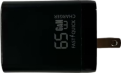
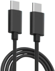
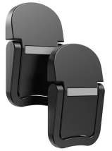
1 x Power Adapter (PD 65W/67W)1 x USB-C Cable2 x Mounting Foot

1.1.2 Installation Guide

  • Power Supply

The supplied power adapter is intended exclusively for powering the mini-extreme ISO.

Do not use it to power additional devices simultaneously. Any system instability resulting from powering external devices with the supplied adapter is the responsibility of the user.

  • Desktop Installation

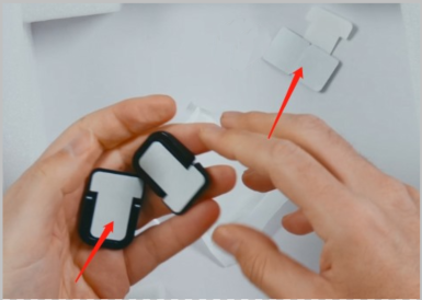
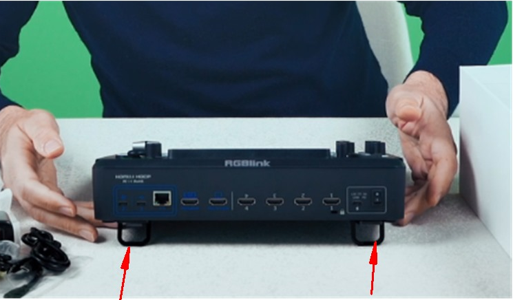
For improved heat dissipation and stable placement, the included mounting feet are recommended. Installation steps:

  1. Remove the white protective film from the adhesive backing.

  1. Attach the mounting feet to the bottom of the device.

  • Non-Desktop Installation

For non-desktop installation requirements, please contact your sales representative for recommendations based on your specific installation environment.

1.2Front Panel

AreaDescription
Function Settingsโ—‹ 5.5" HD Touch Screen โ—‹ SHORTCUTS Custom Function Button โ—‹ MENU/EXIT Button โ—‹ ENTER: Menu Browsing/Confirm Button โ—‹ RECORD Button โ—‹ ON AIR Button
Camera Controlโ—‹ FOCUS knob with indicator โ—‹ ZOOM Toggle โ—‹ 5-Direction Joystick
Volume Controlโ—‹ Volume Control Knob โ—‹ AFV (Audio Follow Video) Button โ—‹ Mute Button
Layer Settingsโ—‹ PICTURE-IN-PICTURE layout selection buttons โ—‹ Chroma Key button โ—‹ A/B Layer selection buttons โ—‹ VIEWS scene recall button โ—‹ EFFECT transition effect selection button โ—‹ DURATION transition duration selection button โ—‹ OVERLAY selection button โ—‹ PROGRAM/B program output and multi-layer preset buttons โ—‹ PREVIEW/A preview output and multi-layer preset buttons
Transitionโ—‹ T-Bar โ—‹ CUT quick transition button โ—‹ AUTO automatic transition button โ—‹ FTB fade-to-black transition button

Function Settings

AreaDescription
5.5-inch Full-Color Display Monitors all audio/video inputs and outputs, recording and streaming status, and displays menus.
SHORTCUTS (Coming Soon) Button Functions โ—‹ Shortcut functions can be assigned through the Web App. Indicator Status โ—‹ Off: No shortcut function is assigned. โ—‹ Solid white: A shortcut function is assigned. Operation โ—‹ Press: Activates the assigned shortcut function.
MENU Button Functions โ—‹ MENU: Opens the menu. โ—‹ Back: Returns to the previous screen. โ—‹ Screen Lock: Press and hold for 3 seconds to lock or unlock the screen.
ENTER Button Functions โ—‹ Selects an option. โ—‹ Confirms a selection. โ—‹ In PTZ control mode, turn the knob to adjust the value.
RECORD โ—‹ Connect a USB drive or hard drive to USB-C 1, then press RECORD to start recording. A solid red indicator indicates that recording is in progress. โ—‹ Recording cannot be started when less than 300 MB of storage space remains. โ—‹ During recording, press RECORD to select whether to stop recording. The indicator flashes red while the recording is being saved.
ON AIR โ—‹ When a streaming address is configured, press ON AIR to start streaming. A solid green indicator indicates that streaming is in progress. โ—‹ The indicator flashes red when no streaming address is configured or a configured streaming address fails. โ—‹ During streaming, press ON AIR to select whether to stop streaming. โ—‹ The indicator turns off when streaming ends.

Camera Control

AreaDescription
FOCUS Knob and Indicator Focus Status โ—‹ Manual focus: The indicator is off. โ—‹ Auto focus: The indicator lights blue. FOCUS Knob โ—‹ Turn: Manually adjusts focus. โ—‹ Press: Enables auto focus and opens the PTZ page.
ZOOM Toggle โ—‹ In layer control mode: Adjusts the size of Layer A and Layer B. โ—‹ In camera control mode: Adjusts the camera zoom. Press + to zoom in and - to zoom out.
Five-Direction Joystick Move up, down, left, or right: โ—‹ In layer control mode: Adjusts the layer position. โ—‹ In camera control mode: Controls camera pan and tilt. Press: In camera control mode: Adjusts the pan/tilt speed.

Volume Control

AreaDescription
Audio Adjustment Knobs โ—‹ The numbered knobs adjust the volume of the embedded audio from HDMI 1โ€“4 and SDI 1โ€“4 inputs. โ—‹ The knobs labeled with audio icons adjust the volume of the microphone input, XLR input, monitor output, and program output.
AFV Button Indicator Status โ—‹ Off: AFV is disabled. โ—‹ Solid white: AFV is enabled. Operation โ—‹ Press: Enables or disables AFV.
Indicator Status โ—‹ Off: Mute is disabled. โ—‹ Solid red: Mute is enabled. Operation โ—‹ Press: Enables or disables mute.

Layer Settings

Picture in Picture
AreaDescription
PICTURE-IN-PICTURE Layout Selection Buttons โ—‹ Press: Selects the layout for the selected layer. The selected layout button lights solid green.
Chroma Key Button โ—‹ Press: Enables chroma keying. Layer B is enabled by default. The button lights solid green.
A/B Layer Selection Buttons โ—‹ Layer A: Main picture. โ—‹ Layer B: Secondary picture. โ—‹ Layers A and B can be combined for PIP. โ—‹ The indicator is off when the layer is disabled or not displayed in Preview. Press a Layer Button โ—‹ Off: Press to select the layer. The indicator lights solid blue. Use ZOOM and the joystick to adjust its size and position. โ—‹ Solid blue: Press another layer button to switch the selected layer. The current layer changes to solid green. โ—‹ Solid blue: Press again to disable the layer. The indicator turns off.

OVERLAY Layer Selection Buttons
AreaDescription
Background Foreground Includes the Background and Foreground buttons. Indicator Status โ—‹ Off: No layer asset is loaded. โ—‹ Solid white: A layer asset is loaded. โ—‹ Solid red: The layer is displayed on the program output. Operation โ—‹ Solid white: Press to add the layer to the program output. The indicator changes to solid red. โ—‹ Solid red: Press to remove the layer from the program output. The indicator changes to solid white.
AreaDescription
VIEWS Recall Buttons Indicator Status โ—‹ Solid green: view saved. โ—‹ Solid red: view recalling. โ—‹ Off: No view is saved. Operation โ—‹ Indicator off: Press and hold to add a view. The indicator lights solid green when the view is saved. โ—‹ Solid green: Press to recall the view to Preview. The indicator changes to solid red. โ—‹ Recall another view: The button for the view being recalled changes to solid green, while the button for the current scene changes to solid red.
DURATION Transition Duration Buttons โ—‹ Default: 1.0 s โ—‹ Options: 0.5 / 1.0 / 1.5 / 2.0 s โ—‹ Selected: Solid white
EFFECT Transition Effect Buttons โ—‹ Default: MIX (fade) โ—‹ For more effects, go to MENU > EFFECT. โ—‹ Selected: Solid white
PROGRAM Program Output Selection Buttons Button Assignment โ—‹ 1โ€“4: HDMI 1โ€“4 โ—‹ 5: SDI 1 / SDI 2 โ—‹ 6: SDI 3 / SDI 4 โ—‹ 7โ€“8: UVC / NDI Operation โ—‹ Press to switch the PROGRAM output to the selected input.
PREVIEW Preview Output Selection Buttons Button Assignment โ—‹ Assign signals via MENU > Input. โ—‹ 1โ€“6: HDMI 1โ€“4 / SDI 1โ€“4 (IN1โ€“IN6) โ—‹ 7โ€“8: IN7โ€“IN8 Operation โ—‹ Press to switch the PREVIEW output to the selected input.

Transition

AreaDescription
T-Bar Manually transitions from Preview to Program using the selected transition effect.
CUT Press to switch between Preview and Program without a transition effect.
AUTO โ—‹ Press to execute the selected transition effect at the selected duration. โ—‹ Flashing red: Transition in progress. โ—‹ Off: Transition complete.
FTB (Fade to Black) Press to toggle the Program output: โ—‹ Off: Displays the actual Program output. โ—‹ Solid red: Fades the Program output to black.

1.3Ports Info

No.PortDescription
โถUSB-C 2Connected to a computer (via USB-C cable) or an Android device (via OTG cable). Recognized as a webcam by a third party software like OBS or zoom to capture and output the program view on air in applications like remote video conference.
โทUSB-C 1[1]โ—‹ Connect to a USB camera as the fifth input signal (default function). โ—‹ Record the Program output view to a USB drive or SSD. โ—‹ Import audio, video, and image files from a USB drive.
โธEthernet Portโ—‹ Streaming: Go live over the internet without a computer. โ—‹ Remote PTZ control via IP VISCA for IP workflow.
โนPROGRAM OutputBy default, it outputs the program feed but can be switched to output test color bars.
โบMULTI-VIEW OutputWhen connected to a display, it monitors all input and output signals simultaneously in a multi-view layout.
โปHDMI 1-4 INโ—‹ Four HDMI input channels for connecting HDMI sources. โ—‹ 4K60 resolution and downward compatible with all resolutions.
โผLocking HoleUse the T-lock to fix the device.
โฝUSB-C Power SocketPD protocol support, 20V 3A.
โพPower SwitchBoat-shaped switch. Press downward to turn on the switch.
โฟHeadphone Output3.5mm mini-jack for audio monitoring.
โ“ซ6.35mm TRS JackBalanced TRS audio output.
โ“ฌLine-inBalanced 6.35mm TRS jack to connect to PC, mobile phone, or audio console.
โ“ญMIC inโ—‹ XLR+TS input port to connect to microphone. โ—‹ 48V Phantom Power supported.
โ“ฎ+48VPhantom Power Switch [2]โ—‹ Default to OFF for safety. โ—‹ Manually enable it when connecting a condenser microphone that requires 48V phantom power.
โ“ฏSDI 1-4 Inputsโ—‹ Four 12G-SDI input ports can be connected to UHD cameras and other input sources. โ—‹ 12G SDI compatible with 6G/3G/HD/SD-SDI.
๐Ÿšจ   Hot-Plugging Warning

48V phantom power supplies operating voltage to condenser microphones through the XLR input.

Do not connect or disconnect microphones or XLR cables while 48V phantom power is enabled.

When phantom power is turned on, voltage is present on the XLR connector. Connecting or disconnecting cables under power may generate current surges that can result inloud pops or unwanted noise,microphone malfunctionordamage to the audio circuitry of the device or connected equipment.


๐Ÿ“ข  Notes

[1] The two USB-C ports are functionally independent. The functions available on one USB-C port cannot be accessed through the other port via a USB hub, docking station, or adapter.  

[2] Phantom power should be enabled only when using a condenser microphone that requires external power. Disable phantom power before connecting other audio devices.


๐Ÿ“ข  Compatibility Notice

Only H.264-encoded UVC cameras are supported for โท UVC input.

Compatibility may vary between UVC camera models and manufacturers. If a connected camera cannot be detected or does not function properly, please contact RGBlink Technical Support.

2Install Your Product

mini-extreme Application

๐Ÿ”” To Know RGBlink Portable Monitor

A mounting slot for the RGBlink Portable Monitor is located on the top of the mini-extreme ISO front panel.

The expansion display provides additional monitoring space and improves operational efficiency.

The RGBlink Portable Monitor features a full-function USB-C interface that supports both power delivery and audio/video transmission. It also includes a Mini HDMI port for connecting external displays, cameras, and other compatible devices.

For information about purchasing the expansion display and related accessories, please contact your sales representative.

2.1 Connecting Power

RGBlink mini-extreme ISO package includes a PD power adapter and power cable.

Before connecting the power supply, make sure the power standard in your country or region is supported.

Firmly connect the power cable to ensure stable power delivery to the device.
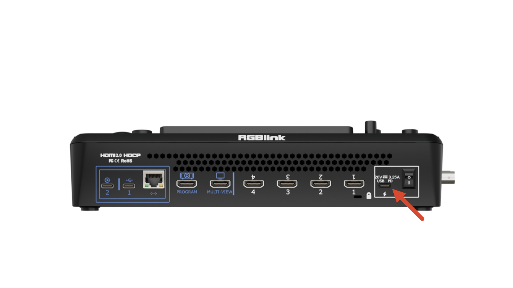
๐Ÿ“ข  Important

It is recommended to use the power adapter included with the package. 

If another adapter must be used, make sure it meets the following requirements:  

- Supports the PD fast charging protocol 
- Uses a USB-C power port with reversible plug orientation 
- Provides a minimum output power of 60 W

If the power adapter has two ports, use only the USB-C port for powering mini!

2.2 Powering on mini-extreme ISO

Press the rocker power switch downward to power on the rear panel.
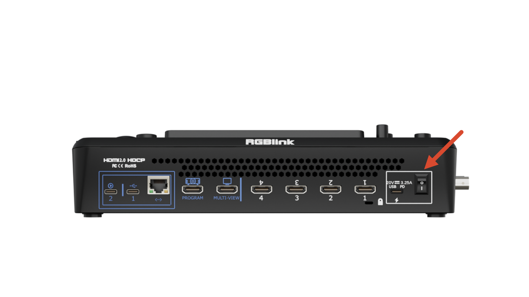
๐Ÿ‘‰

After startup, the full-color display will show the mini-extreme ISO logo before entering the main operating interface.

2.3 Connecting Router

It is recommended to connect mini-extreme ISO to a network before use so that the device can be updated to the latest system version when available.

  • Connect the Ethernet port of mini-extreme ISO to a router using a CAT6 Ethernet cable.
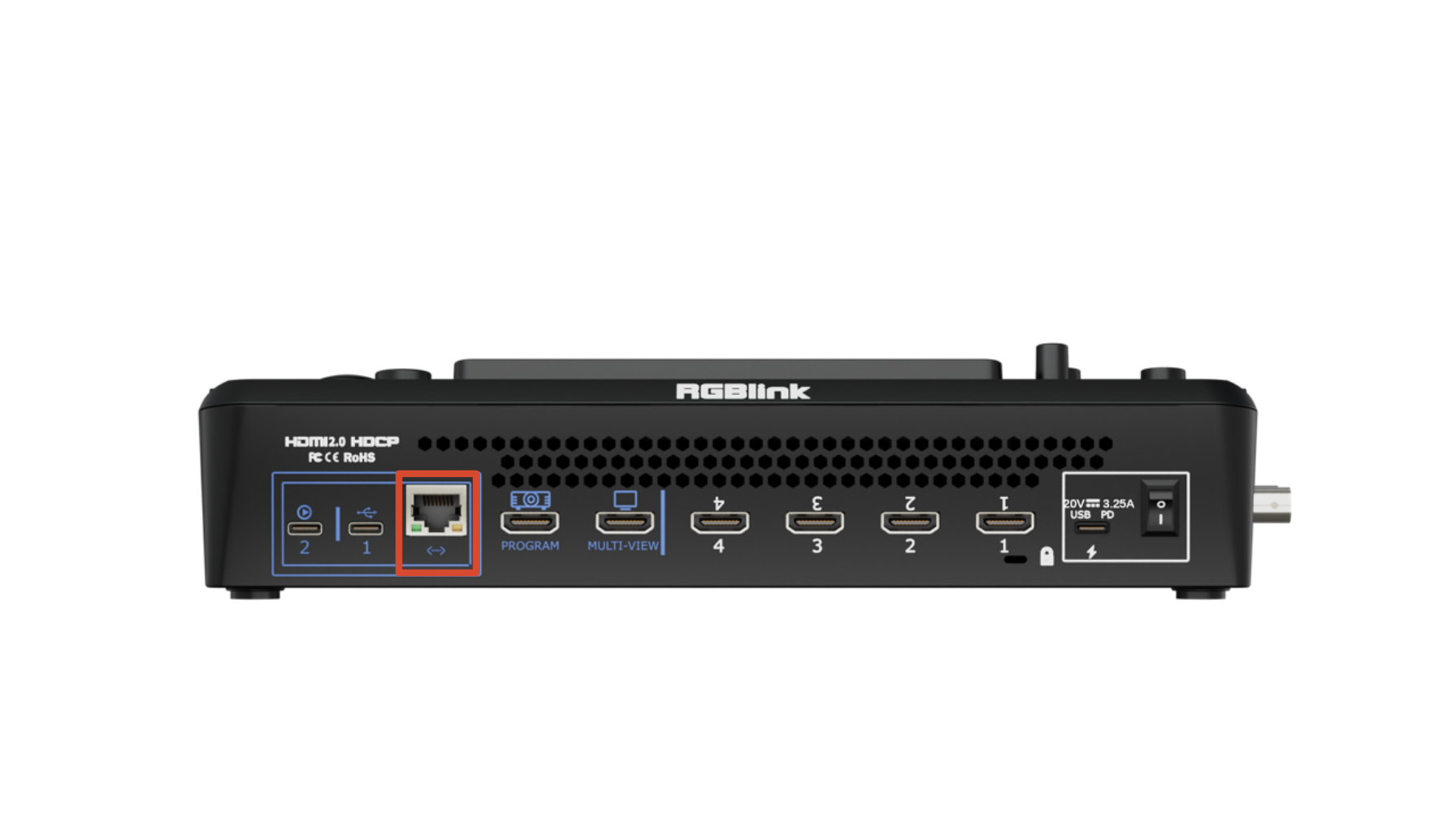
๐Ÿ‘‰
  • Select either DHCP or Static IP mode according to your network environment.
๐Ÿ“ข  Important

mini-extreme ISO and the router must be on the same network segment (subnet) to communicate properly.  

  • DHCP Mode
    1. Press MENU to open the menu.
    2. Go to SETTINGS > IP Setting.
    3. Enable DHCP. The device will automatically obtain an IP address.
  • Static IP Mode
    1. Press MENU to open the menu.
    2. Go to SETTINGS > IP Setting.
    3. Disable DHCP.
    4. Use ENTER knob to edit the IP address.
    5. Press ENTER to save the settings.

2.4 Connecting HDMI/SDI Signal Sources

mini-extreme ISO provides four HDMI inputs and two 12G-SDI inputs, supporting video input resolutions up to 4K60 with automatic deinterlacing.

Cameras, computers, and other devices equipped with HDMI or SDI output interfaces can be connected to mini-extreme ISO as video input sources.

HDMI PortSDI Port

The built-in 5.5-inch display automatically detects and previews connected video sources after startup. An external monitor may also be connected via HDMI output for source monitoring or multiview operation.

๐Ÿ“ข  Notes

HDMI and SDI cables are not included and must be purchased separately. 

Some cameras use Mini HDMI connectors. If required, purchase a Mini HDMI-to-HDMI cable separately.

2.5 Connecting Monitoring Devices

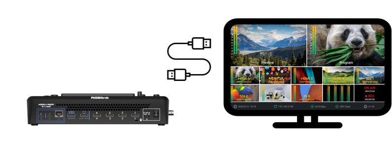
mini-extreme ISO provides MULTI-VIEW and PROGRAM output ports, allowing simultaneous connection to monitors for production and monitoring. For output configuration details, see 3.4 Output.
๐Ÿ‘‰
  • MULTI-VIEW: Connects to a monitor. Outputs the multiview monitoring screen by default.
  • PROGRAM: Connects to a projector, LED display, television, or other display device. Outputs the program feed by default.
2.6 Connecting Microphones and External Monitoring Devices

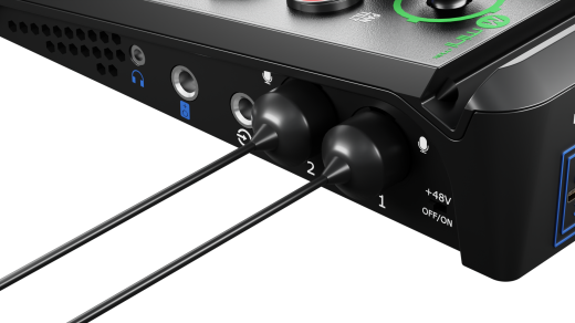
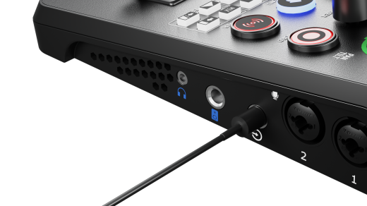
mini-extreme ISO provides three external audio input ports and two audio output ports on the right-side panel for microphone connection and real-time monitoring, supporting live streaming and audio mixing workflows.

2.6.1 Audio Inputs

  • Line In

The Line In connector uses a 6.35 mm TRS jack and supports connection to computers, smartphones,tablets, audio mixers and other audio devices.

  • MIC Input

The MIC input uses a combo XLR/TRS connector and supports 48V phantom power.

It can be connected directly to powered or passive microphones.

  • When connecting dynamic microphones, wireless microphone receivers, or other audio devices, phantom power must remain disabled.
  • Enable phantom power only when using a condenser microphone that requires 48V power.
๐Ÿšจ  Warning

Do not connect or disconnect microphones or XLR cables while 48V phantom power is enabled, as this may damage the device or the connected microphone.

  • Operation
    • Connecting a Microphone
      1. Make sure 48V phantom power is turned off.
      2. Turn the MIC level down to minimum.
      3. Connect the XLR cable securely to the microphone and the device.
      4. Enable 48V phantom power.
      5. Gradually raise the MIC level to the desired volume.
    • Disconnecting a Microphone
      1. Turn the MIC level down to minimum.
      2. Disable 48V phantom power.
    1. Wait approximately 5โ€“10 seconds for any residual voltage to dissipate.
    2. Disconnect the XLR cable and remove the microphone.

2.6.2 Audio Outputs

  • Line Out: 6.35 mm main audio output.
  • Headphone Output: 3.5 mm headphone monitoring output for real-time audio monitoring.

2.6.3 Embedded Audio

mini-extreme ISO supports embedded audio carried over HDMI and SDI signals. The AFV button on the front panel enables AFV, allowing audio sources to switch automatically with the selected video source.

๐Ÿ“ข  Notes

1. To prevent speaker damage or loud pops
- Connect audio cables before powering on speakers. 
- Power off speakers before disconnecting audio cables. 

2.  Wireless microphone connection
- MIC supports connecting wireless microphone 3.5mm TRS cables via a 3.5mm female to 6.35mm male mono adapter. 
- Line-in supports connecting wireless microphone 3.5mm TRS cables via a 3.5mm female to 6.35mm male stereo adapter.

3. Audio signal limitations
- Balanced signals are supported only on MIC inputs. 
- Stereo input signals are supported only through the Line In interface.

2.7 UVC Capture Output/Input

mini-extreme ISO provides two USB 3.0 ports for streaming and local recording.

2.7.1 UVC Output (USB-C 2)

When connected to a computer via USB, mini-extreme ISO is recognized as a standard USB webcam.

The device can then be selected as a video source in applications such as OBS Studio, Zoom and other compatible streaming platforms.
๐Ÿ‘‰

2.7.2 UVC Input (USB-C 1)

Connect a UVC-compatible camera to USB-C 1. The video source will be available as an input and displayed in the IN5 or IN6 view.

๐Ÿ“ข  Notes

UVC input supports only UVC cameras using the H.264/H.265  video encoding format. MJPEG encoded video streams are not supported. 

Due to differences in UVC protocol implementation among manufacturers, mini-extreme ISO may not be compatible with all UVC cameras. For the latest list of compatible devices, please contact RGBlink Technical Support.

2.7.3 Recording and Media Import (USB-C 1)

Users can connect USB flash drives or SSDs for recording.

An SSD is recommended for multi-channel recording.
๐Ÿ‘‰
๐Ÿ“ข  Notes

- USB 3.0 flash drives are recommended for optimal recording performance. 
- SSDs are recommended for external storage. Verify whether additional power is required before use. 
- The OTG cable used for recording supports file transfer only and cannot be used for live streaming. 
- Simultaneous multi-platform streaming, or using UVC output while recording, may increase CPU utilization and result in dropped frames or video stuttering. 
- Internal USB-C data transmission operates over USB 3.1.

3Use Your Product

Once installation and setup are complete, refer to this chapter for operating instructions.

The interfaces, images, and illustrations in this chapter are for reference only. Actual displays may vary by version. Please refer to the actual interface on your device.

3.1Operation

3.1.1 Buttons and Touchscreen

mini-extreme ISO combines physical buttons and touchscreen controls to support different operating preference.

  • The front panel features multifuncion buttons for quick access to commonly used functions.
  • the built-in 5.5-inch full-color touchscreen supports video monitoring, menu settings and other visual operations.

3.1.2 Web APP

mini-extreme ISO supports browser-based control through Web App, with no software installation required.

On mini-extreme ISO:

  1. Complete network connection as described in chapter 2. Install Your Product, Connecting a Router.
  2. Press Menu
  3. Go to SETTINGS > IP Setting
  4. Enable DHCP to obtain an IP address automatically.

On a computer connected to the same network:

  1. Open a web browser and enter the device IP address in the address bar.
  2. Press Enter.
  3. The Web App interface will open. You can switch sources, configure settings, and perform other remote operations.

3.1.3 TAO Cloud

See chapter 3.15 Tao Cloud.

3.2Main Interface and Menu

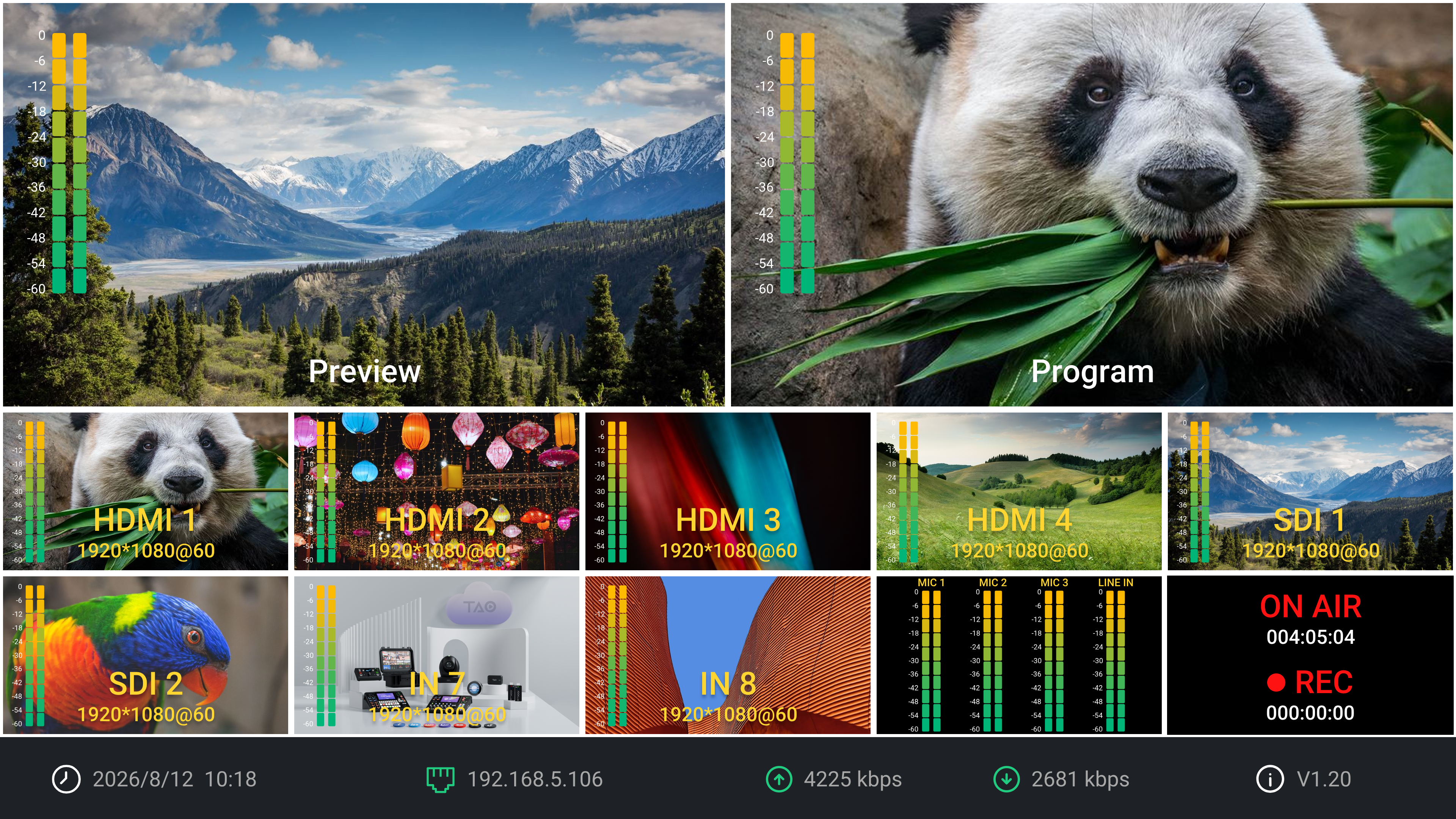
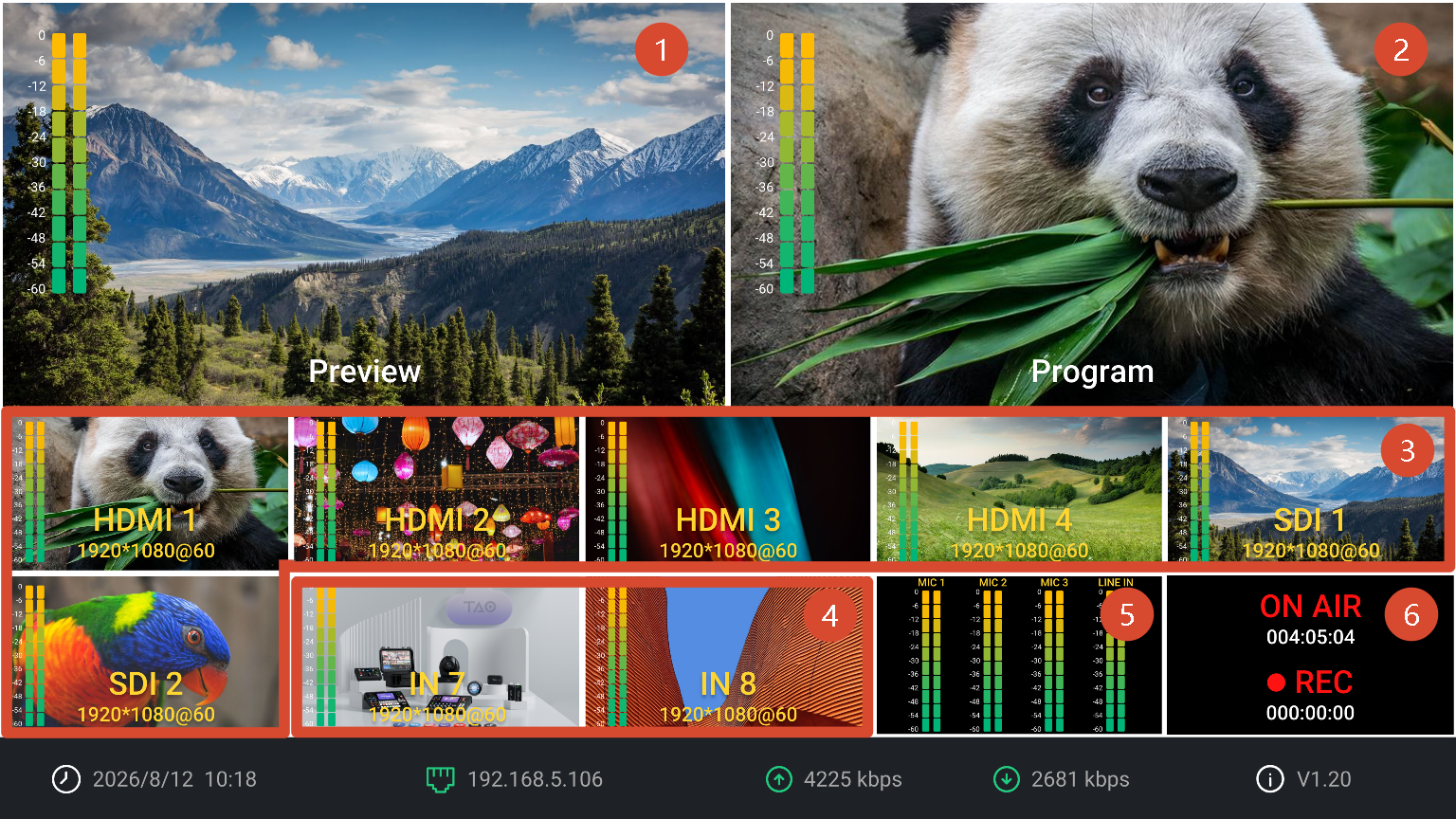
The main interface is the default operating screen of mini-extreme ISO.

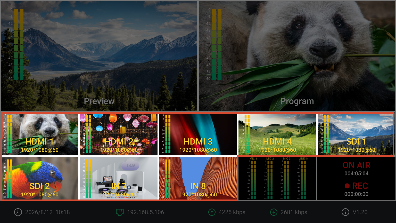
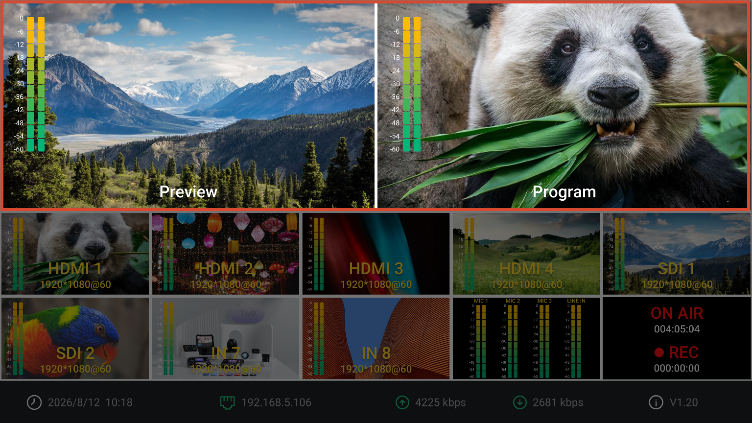
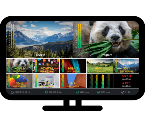
It uses a multiview layout to display input sources, Preview, Program, audio status, recording status, and streaming status in real time.

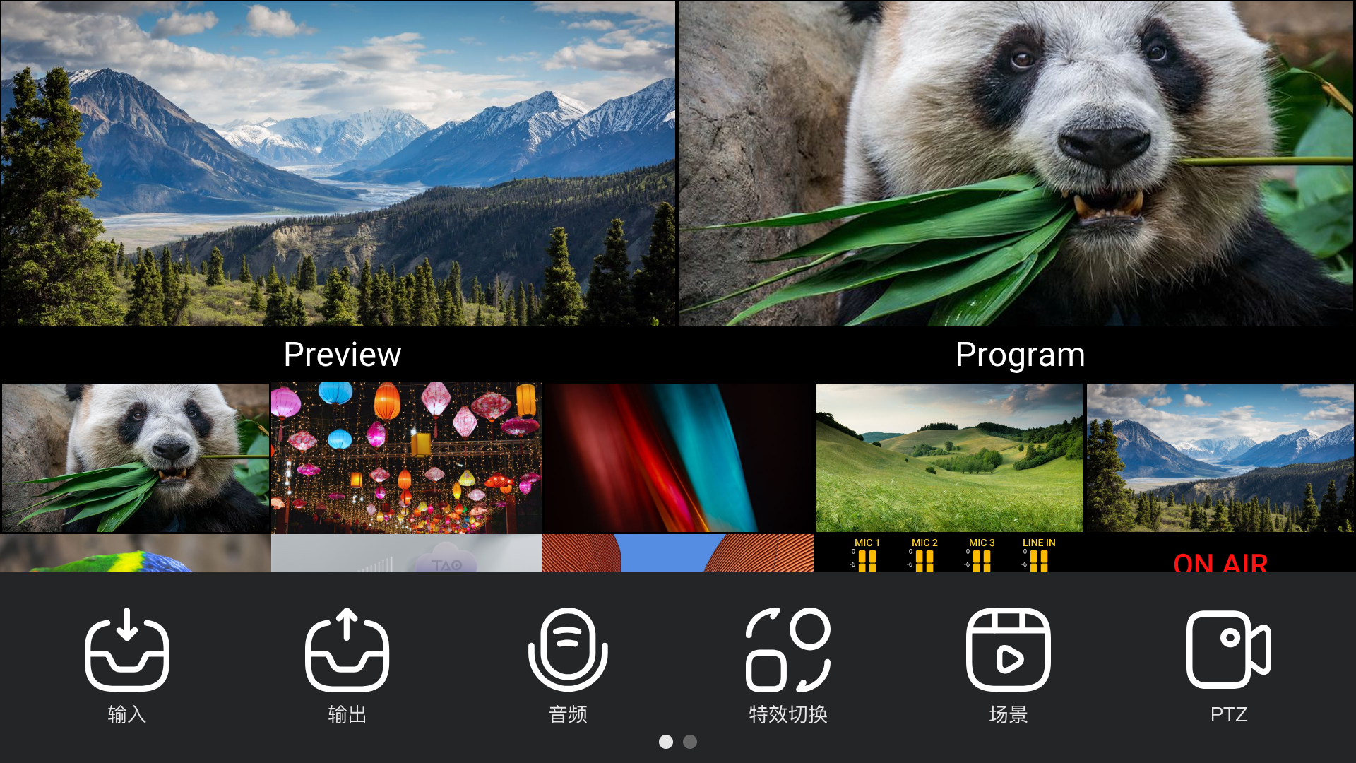
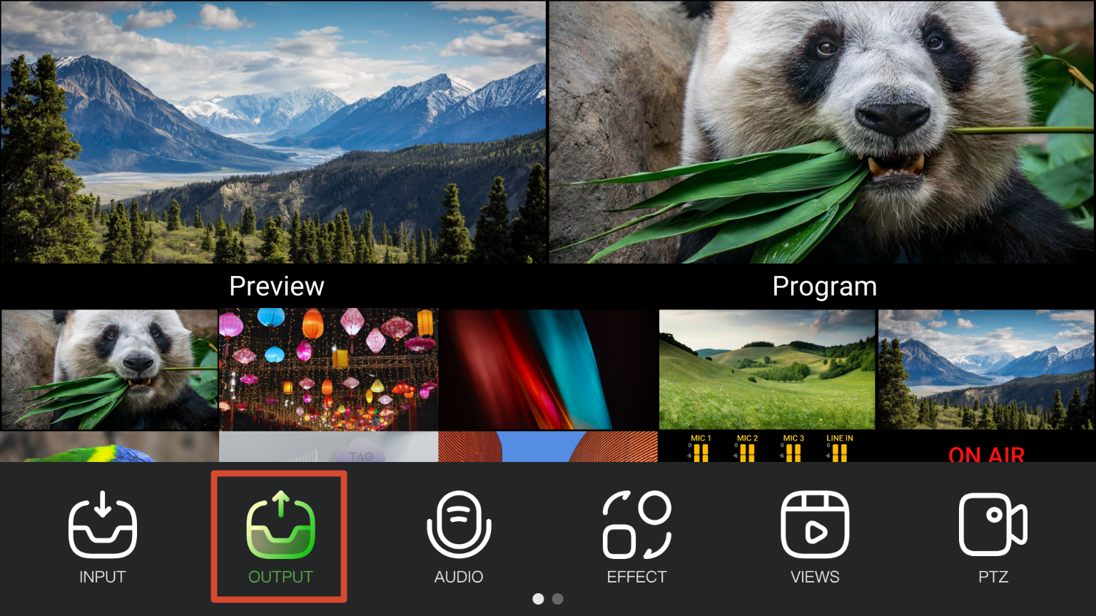
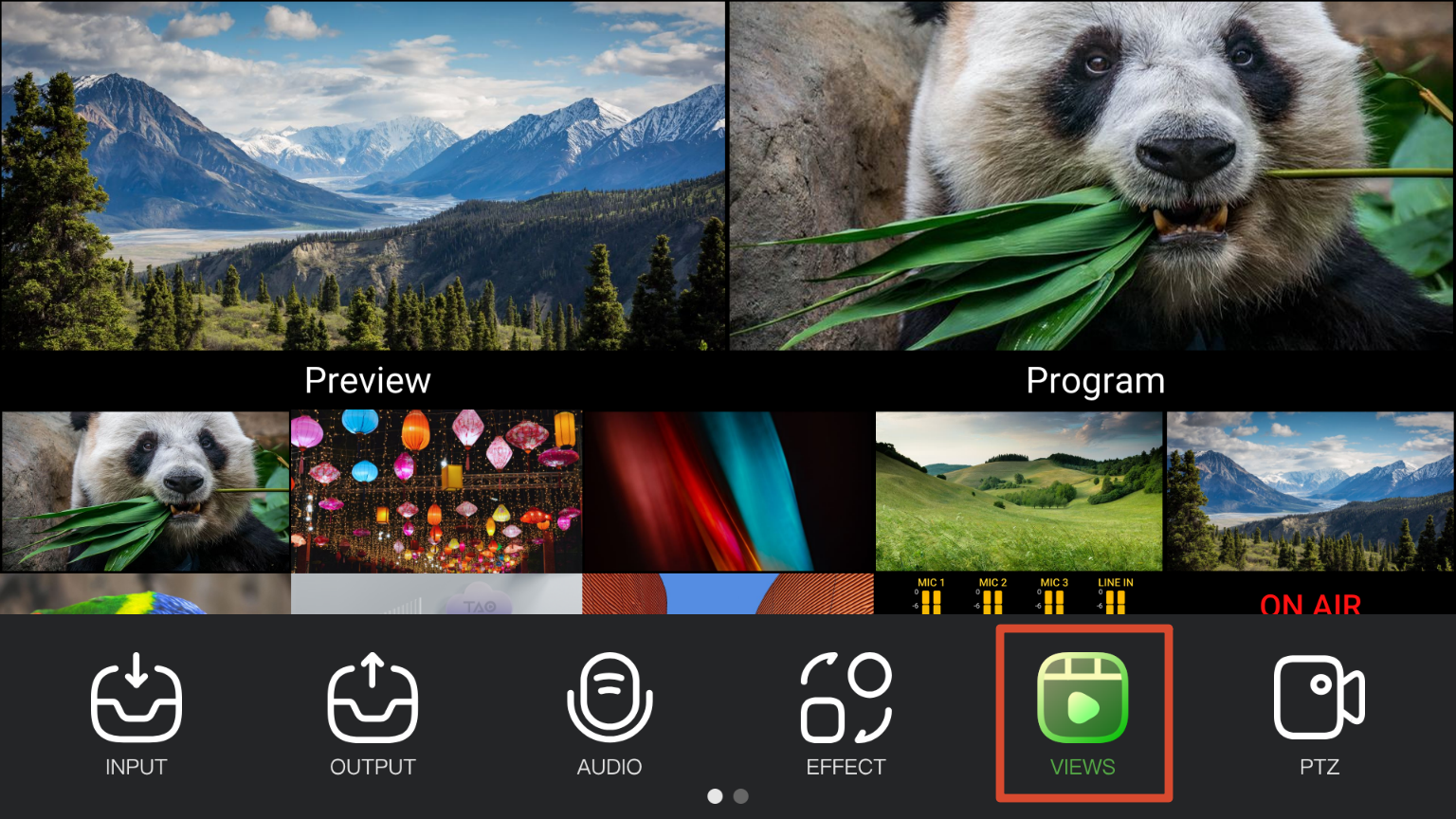
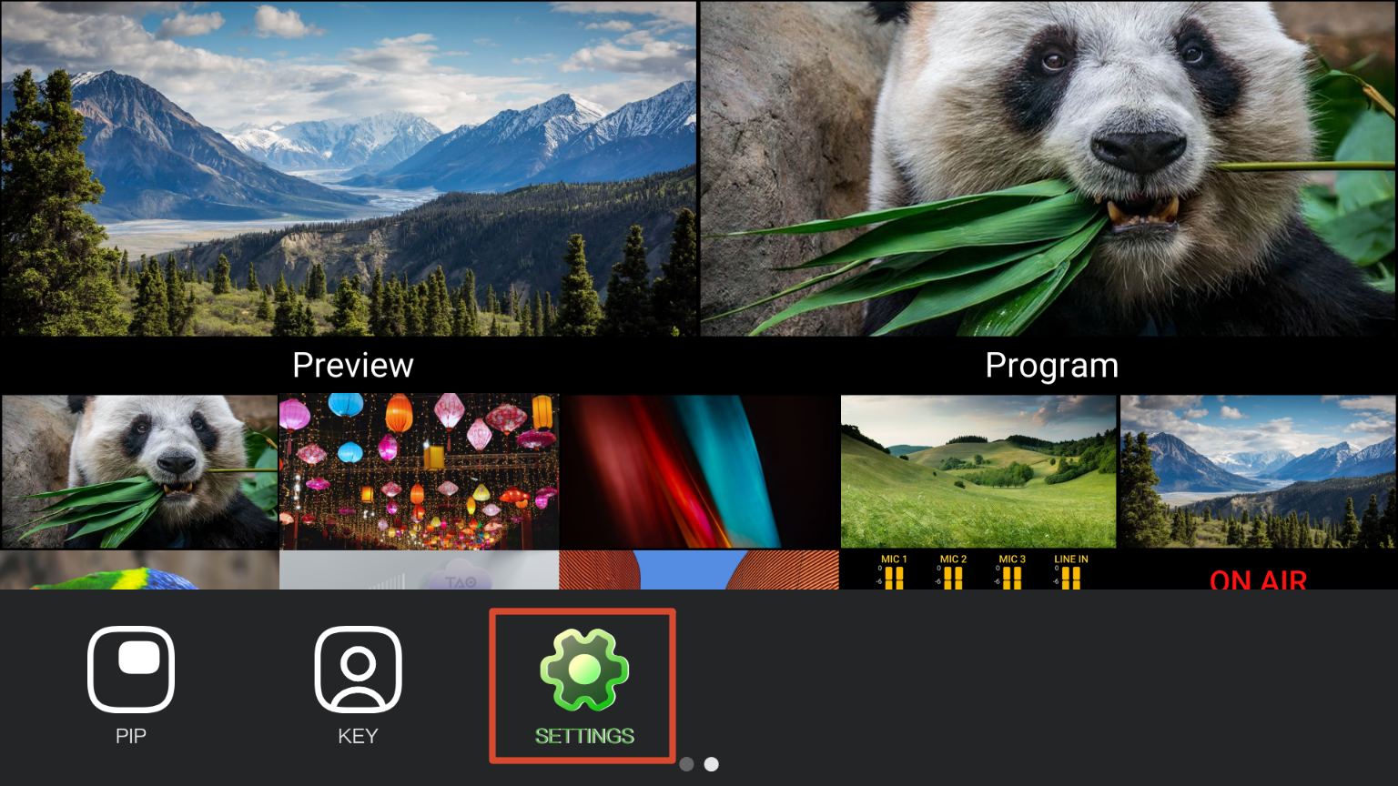
Press MENU to display the menu bar at the bottom of the screen. Swipe left or right on the menu bar to switch between function pages. Press MENU again to hide the menu bar.

๐Ÿ‘‰

Main Interface Overview

AreaDescription
โถ PreviewDisplays the current Preview image and audio meters. Used for program preview and effect preparation. Transitions, audio mixing, overlays, and other settings can be adjusted before switching to Program.
โท ProgramDisplays the current Program output and audio meters. Program is the final output sent to recording, streaming, or external display devices. For switching Preview to Program, see chapter 3.8 Switching Modes.
โธ HDMI/SDI SourcesDisplays HDMI and SDI input sources and audio meters. For source assignment, see chapter 3.3 Input.
โน NDI/UVC SourcesDisplays NDI decoded sources or USB camera sources. For source assignment, see chapter 3.3 Input.
โบ Audio StatusDisplays audio meters for microphone and Line-in inputs.
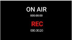
โป Recording and Streaming StatusDisplays recording and streaming duration, as well as the current recording status.

3.3Input

INPUT settings are used to assign signal sources to IN 1-8, including HDMI 1-4, SDI 1-4, NDI and UVC sources.

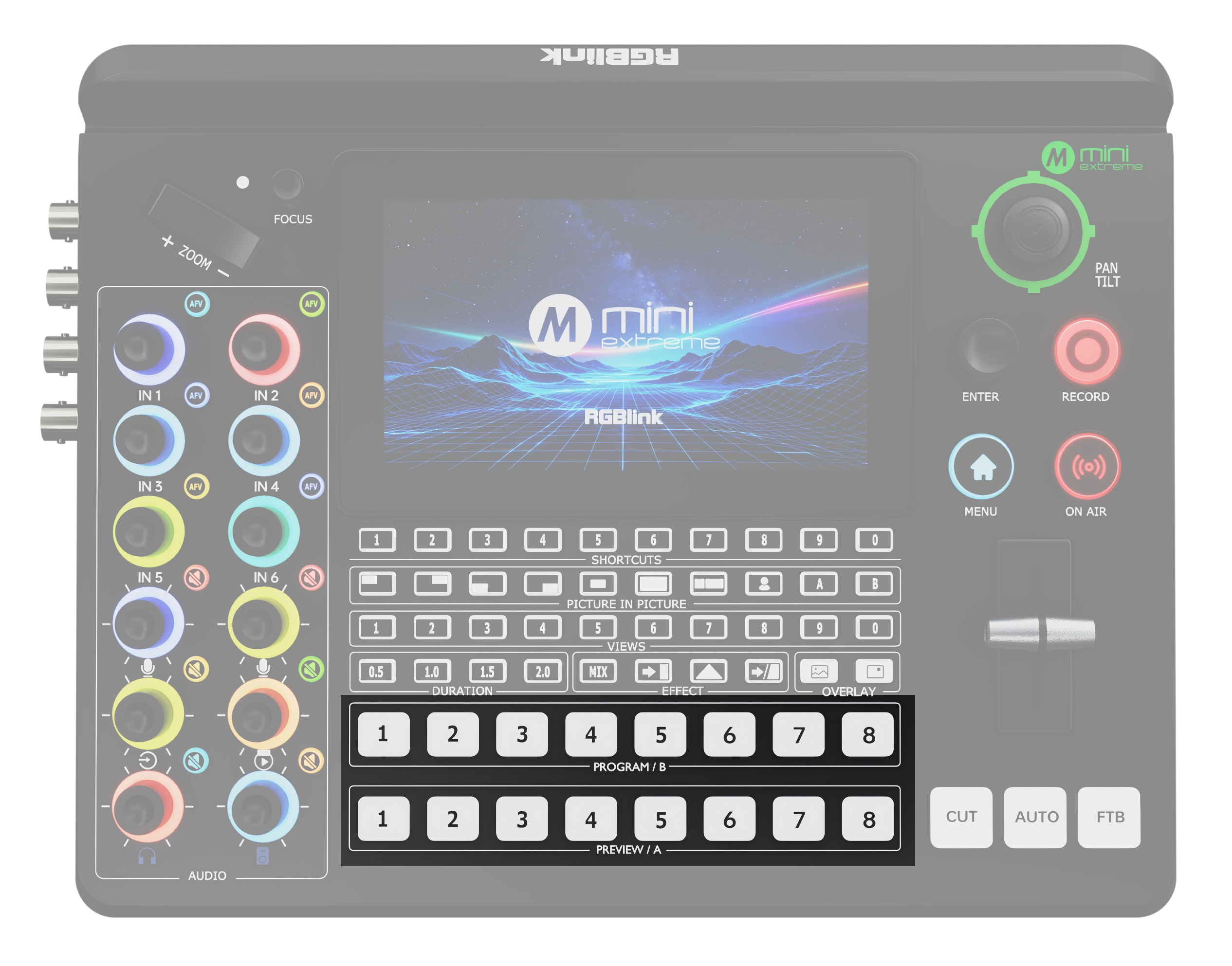
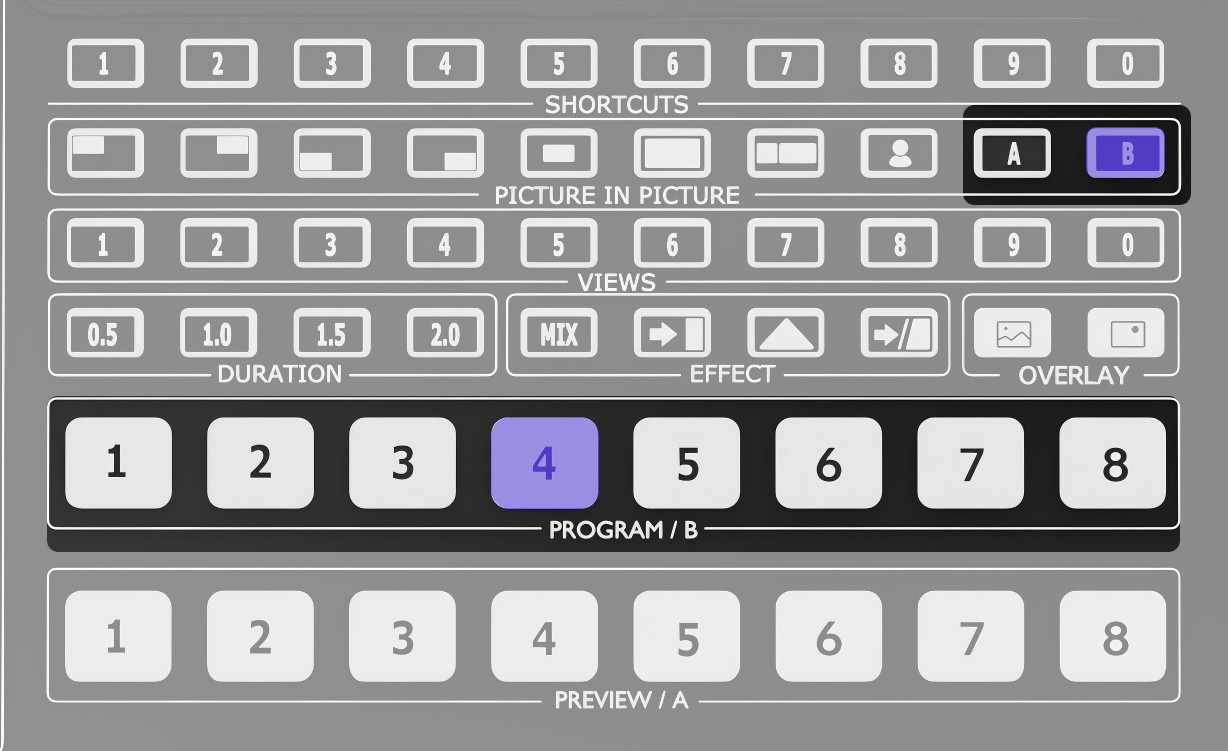
IN 1-8 correspond to the buttons on the PROGRAM/B and PREVIEW/A rows from the front panel (as highlighted in the box) .

After a souce is connected, the button indicator displays the corresponding status.

Indicator StatusDescription
Solid GreenThe signal is currently displayed in PREVIEW.
Solid BlueThe signal is being editing.
Solid RedThe signal is currently displayed in PROGRAM.
OffNo signal is detected. Or the signal format is not supported.

3.3.1 IN1-6

IN1-6 are assigned to HDMI and SDI input sources.

After connecting a source as described in chapter 2. Install Your Product, the corresponding input is displayed in the HDMI/SDI monitoring area on the main interface.

Main Interface-HDMI/SDI Souces Monitoring

InputSource
IN 1-4HDMI 1-4
IN 5SDI 1 or SDI 2
IN 6SDI 3 or SDI 4

Configuration

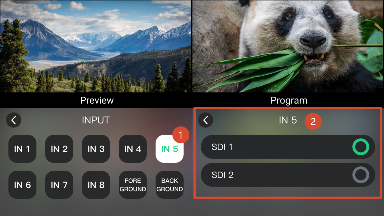
The following example shows how to configure IN 5:

  1. Press MENU to open the menu.
  2. Select INPUT.
  3. Select IN 5.
  4. Select the signal source.

EDID Management

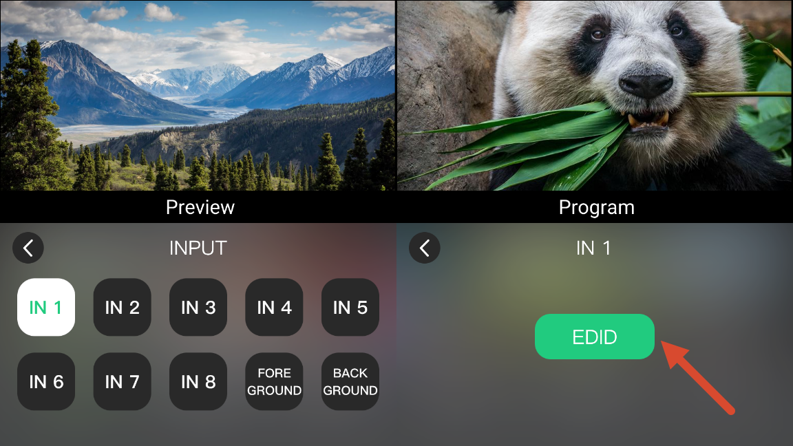
IN 1-4 support EDID management.

Click the โš™icon in the upper-right of the INPUT page to open EDID management page.

๐Ÿ‘‰

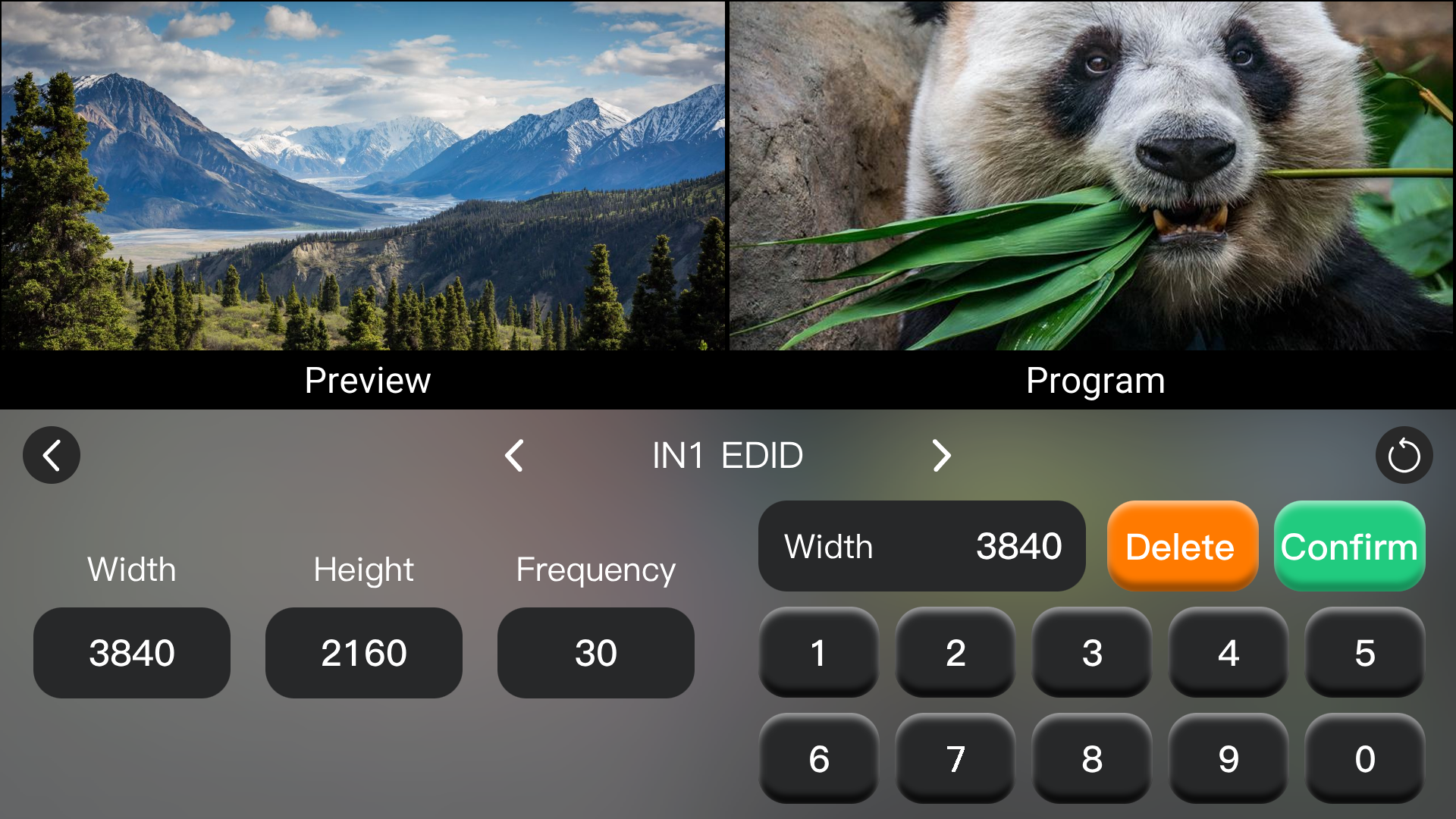
The following parameters can be configured using the on-screen numeric keypad.

ParameterRange
Width800-3840
Height600-2160
Frequency25-120 fps

3.3.2 IN7-8

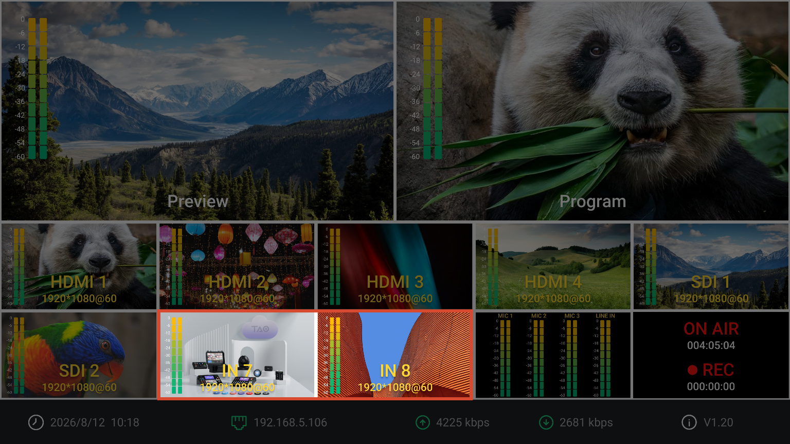
IN 7 and IN 8 support UVC camera sources and NDI video streams.

Select either a local UVC source or an NDI source on the local network as required. The assigned sources are displayed in the IN 7 and IN 8 monitoring area on the main interface.

Main Interface-IN 7-8 Souces Monitoring

๐Ÿ“ข  Important

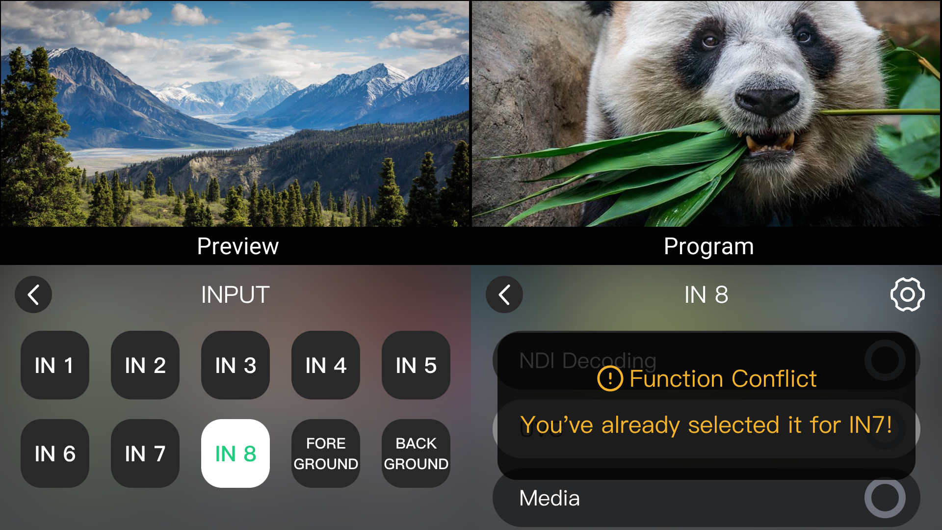
IN7 and IN8 are mutually exclusive. If one is set to UVC, the other only supports NDI.

Configuring a UVC Source

  1. Connect a UVC cameras using the H.264/H.265 video encoding format to the UVC port.
  2. Select IN 7 or IN 8.
  3. Set the input type to UVC.

If UVC has already been assigned to either IN 7 or IN 8, the other input cannot be configured as UVC. A "Function Conflict" message will be displayed.

๐Ÿ“ข  Notes

UVC input supports only UVC cameras using the H.264/H.265  video encoding format. 

MJPEG encoded video streams are not supported. 

System Message Example

Configuring a NDI Source

NDI decoding requires TAO Cloud binding and authorization.

  1. Bind the device according to chapter 3.15 TAO Cloud.
  2. Go to My Collection > Device and select the device.
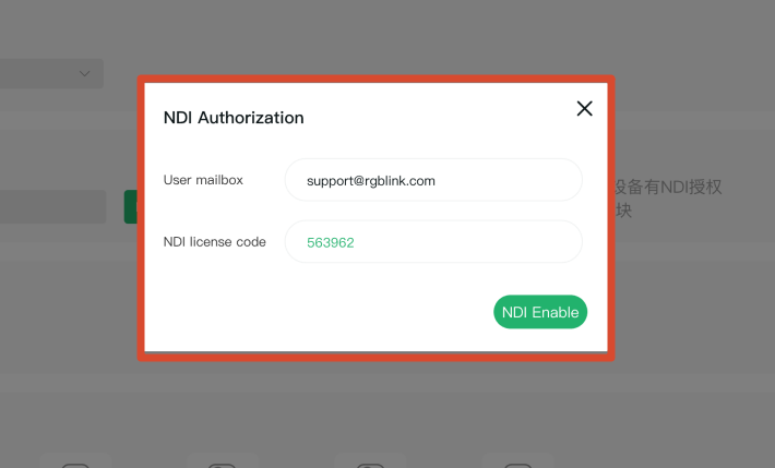
  3. In Setting > NDI Authorization, enter an email address to receive the authorization code, then click Authorization.
  4. Enter a valid NDI authorization code in the pop-up window and click NDI Enable to activate NDI decoding.

On the INPUT page:

  1. Ensure mini-extreme ISO and the NDI source are connected to the same LAN.
  2. Select IN 7 or IN 8 and set the input type to NDI Decoding.
  3. Click the arrow on the right, then tap Enable.
  4. Click Refresh.
  5. Select the target NDI source from the device list.
  6. Ensure mini-extreme ISO and the NDI source device are connected to the same local network.
  7. Select IN 7 or IN 8, then set the input type to NDI Decoding.
  8. Click โš™ then Enable.
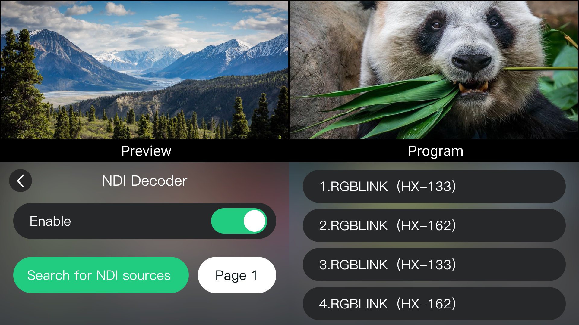
  9. Click Search for NDI Sources.
  10. Select the target NDI source from the device list. Use the page controls to switch between pages.

NDI Source Search Example

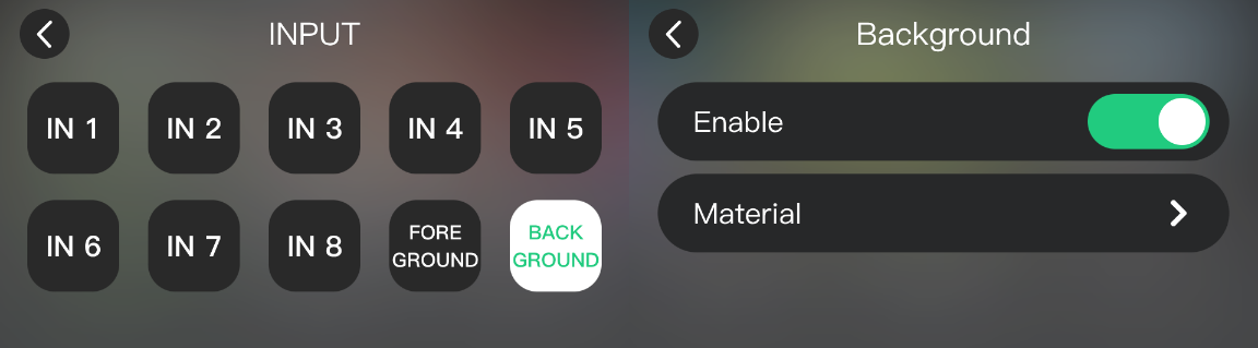
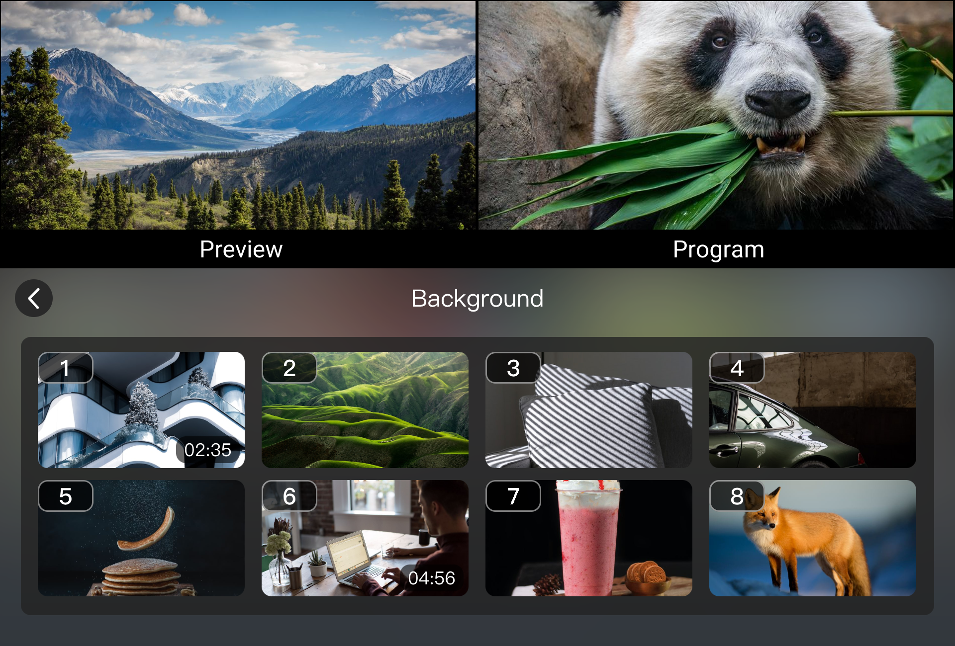
3.3.3 Background and Foreground
Background and Foreground are used to display media assets when no input signal is available or when overlay content is required.
  • Background displays a fixed background image or replaces a black screen.
  • Foreground displays overlay elements such as logos, corner graphics, and masks.
๐Ÿ“ข  Notes

Media assets must be imported into the media library before use. See 3.5 About Layers, Importing Materials for more details.

Configuration

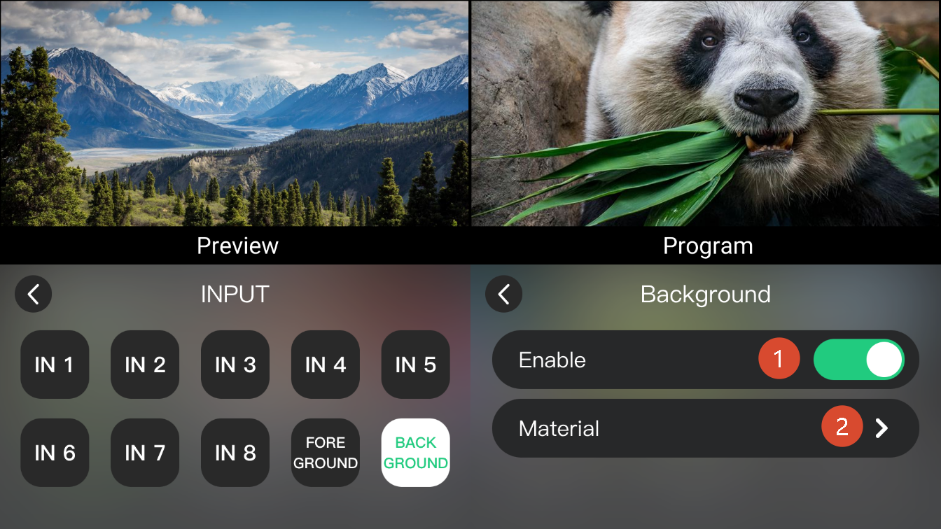
  1. Select INPUT menu
  2. Enable BACKGROUND or FOREGROUND.
  3. Click Material to open the media library and select an asset.
๐Ÿ‘‰

3.4Output

mini-extreme ISO provides two output modes.

  • Preview output for monitoring input sources and device status.
  • Program output for display devices, recording devices, or streaming platforms, delivering the final program output.

3.4.1 Preview

Preview output is displayed on a monitor connected to the MULTI-VIEW port.

MULTI-VIEW Output

The MULTI-VIEW port outputs a fixed 12-window multiview layout at 1080P60.

The built-in 5.5-inch touchscreen displays the same multiview content.

๐Ÿ“ข  Notes

The MULTI-VIEW resolution is fixed at 1080P60 and cannot be changed.

3.4.2 Program

Program output is displayed on a monitor connected to the PROGRAM port.

You can also connect USB-C 2 to a computer using a USB cable.

The computer will recognize mini-extreme ISO as a USB camera source, allowing the program output to be used directly in third-party streaming and conferencing applications.

๐Ÿ“ข  Notes

The UVC output follows the PGM output and cannot be configured independently.

PROGRAM Output

Test Screen

The test screen function can be used to output color bars for connection verification.

  1. Press MENU.
  2. Select OUTPUT > test screen.
  3. Enable color bar.

Select test screen as the program output

3.4.3 Resolution

mini-extreme ISO supports output resolutions up to 3840 ร— 2160@60 Hz.

The default output resolution is 3840 ร— 2160@60 Hz and is automatically compatible with lower-resolution display devices.

Custom output resolutions are also supported.

  1. Select MENU > OUTPUT > Format.
  2. Select the desired output resolution.
  3. Click Confirm.
๐Ÿ‘‰

3.5About Layers

mini-extreme ISO combines multiple layers to create the final Program output. The output image consists of the following layers:

LayerTypeDescription
Layer ADynamicMain video layer.
Layer BDynamicSecondary video layer for PiP or dual-screen display.
BackgroundStaticDisplay background images.
ForegroundStaticDisplay logos, corner graphics, or other overlays.

mini-extreme ISO sipports Picture in Picture and Chroma Key functions.

3.5.1 Adding Layer A/B

Layer A and Layer B are the main video layers used to create the Program output.

By default:

  • Layer A is used as the main video.
  • Layer B is used as the secondary video.

Combining Layer A and B enables single-screen, picture-in-picture, and dual-screen layouts.

Adding Layer A

  1. Press the A button in the PICTURE IN PICTURE row on the front panel.
  2. Confirm that the A button lights blue.
  3. Select a source from the PROGRAM/B row.
  4. Confirm that the corresponding source button lights red.

The selected source will be output as Layer A in the Program output.

Alternatively:

  1. Select a source from the PREVIEW/A row.
  2. Confirm that the corresponding source button lights blue.

Perform switching according to the current switch mode:

  • CUT mode: Press the corresponding source button in the PROGRAM/B row to switch the source to Program output.
  • AUTO mode: Press the AUTO button or move the T-Bar to complete the transition.

Adding Layer B

  1. Press the B button in the PICTURE IN PICTURE row on the front panel.
  2. Confirm that the B button lights blue.
  3. Select a Layer B source using the same method as adding Layer A.

After Layer B is added, mini-extreme ISO enters picture-in-picture mode.

๐Ÿ“ข  Notes

mini-extreme ISO uses single-screen mode by default. After Layer B is enabled, the system automatically switches to dual-layer mode.  

3.5.2 Picture in Picture

Picture-in-picture displays Layer A and Layer B simultaneously. Users can adjust the layout, position, and size of each layer.

mini-extreme ISO provides six built-in picture-in-picture layouts and one single-layer layout.

Switching Layout

  1. Using the front panel
    1. Enable Layer A and B
    2. Using the layout buttons in the PICTURE IN PICTURE row to select a layout.

The Layout Buttons

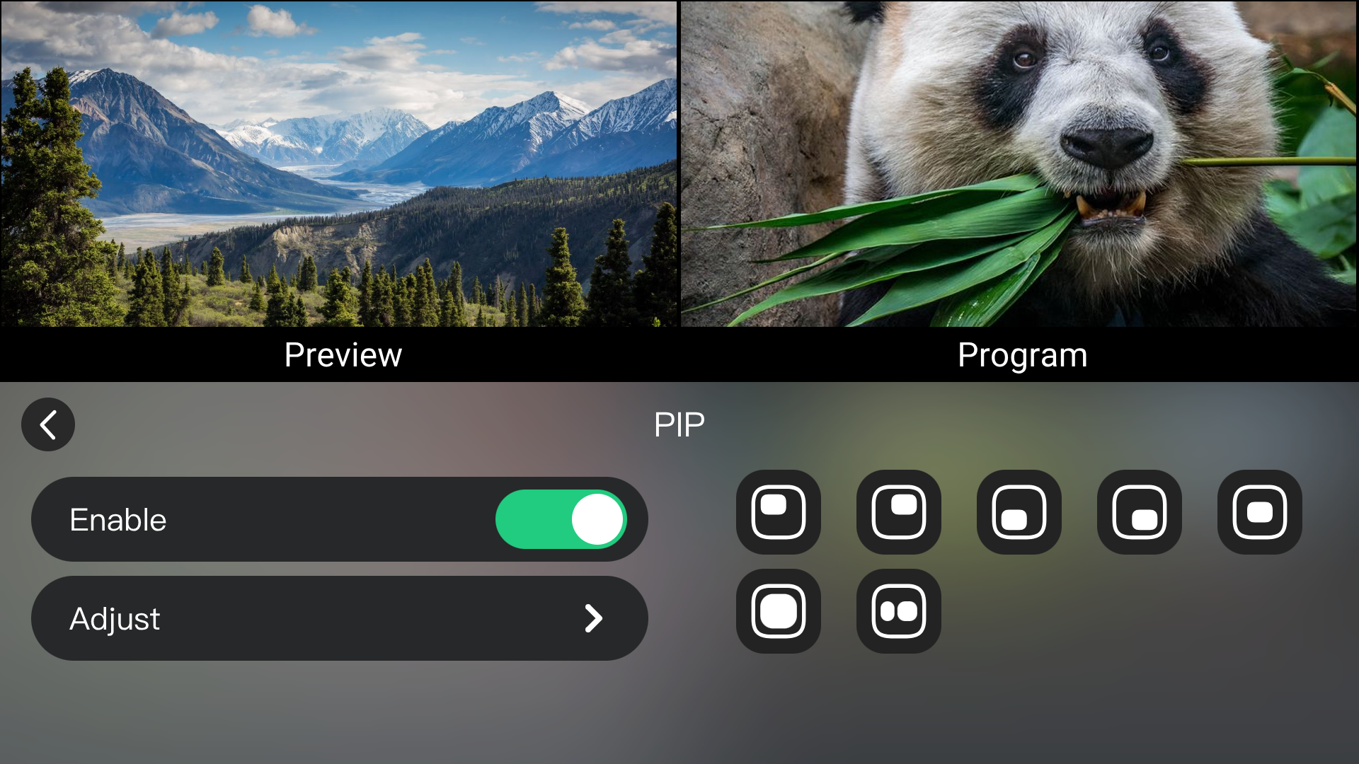
  1. Using the menu
    1. Go to MENU > PIP
    2. Press Enable. Then select a layout.

PIP menu example

Adjust Layers

Layer A and B can be adjusted independently for position, size, and aspect ratio.

  1. Select a layer to edit. The corresponding button will light blue.
  2. Use ZOOM toggle to adjust the size.
  3. Use 5-Direction joystick to adjust the horizontal/vertical position.
  4. Or go to MENU > PIP > Adjust and enter PIP adjust page.

PIP adjust page example

Available settings:

SettingDescription
LayerSelect Layer A or B.
9:16Switch to vertical aspect ratio.
Full ScreenRestore full screen display.
ResetRestore the original state.
ScaleAdjust image size and position.
CropCrop image edges.

3.5.3 Adding Background and Foreground
Background and Foreground layers are used to enhance the Program output.
  • Background replaces the black screen or displays a fixed background image.
  • Foreground displays logos, corner graphics, masks, and other overlay elements.
Supported format:

ParametersRequirement
FormatPNG
Color Depth24 bit
Maximum Resolution3840 ร— 2160
Importing Materials
  1. Connect a USB flash drive to USB-C 1.
  2. When the USB drive is detected, the RECORD button lights up.
  3. Select Input > Background or Input > Foreground to open the asset menu.
  4. The following folders will be created in the root directory of the USB drive (or can be created manually):
  • mini-extreme/background
  • mini-extreme/foreground
  1. Prepare PNG images that meet the format requirements.
  • Name background images back1, back2, back3, etc.
  • Name foreground images fore1, fore2, fore3, etc.
  1. Copy background images to mini-extreme/background.
  2. Copy foreground images to mini-extreme/foreground.
๐Ÿ“ข  Notes 

- Asset folders are created only after entering the corresponding asset page.
- If the folders are not created automatically, create folders with the same names manually.
- Preview and Program share the same Background and Foreground assets. Different assets cannot be assigned separately.
Adjusting Materials

  1. Select the Background Layer or Foreground Layer.
  2. Use the ZOOM toggle to adjust the size.
  3. Use the 5-Direction joystick to adjust the position.

Applying Materials

The PREVIEW and PROGRAM rows on the front panel provide shortcut buttons for Background and Foreground. Press the corresponding button to add or remove an asset.

Left: Background; Right: Foreground
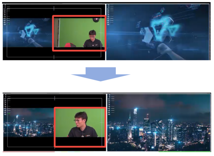
3.5.4 Chroma Key

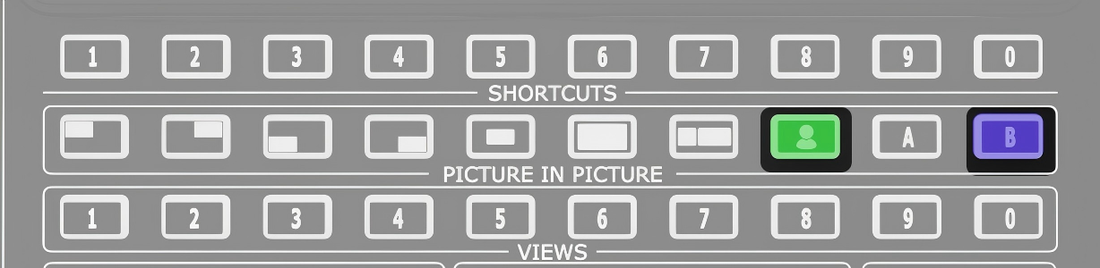
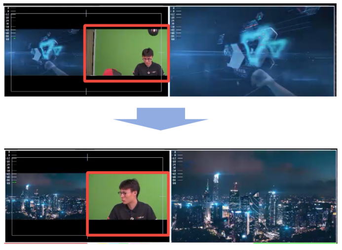
Chroma key removes the background and overlays the subject onto other layers. The chroma key function applies to Layer B by default.

Using the Front Panel

  1. Congigure the Layer B
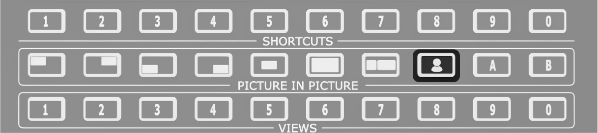
  2. Press the chroma key button (as highlighted). The system displays the chroma key preview.

the chroma key button

Using the MENU

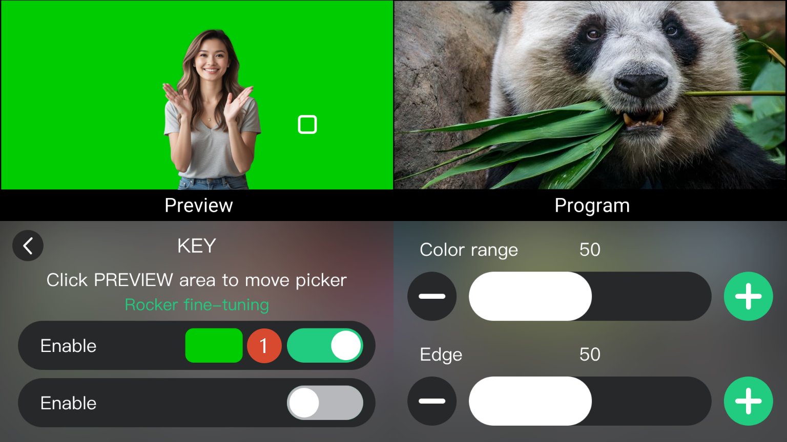
  1. Go to MENU > KEY
  2. Enable the picker (see โ‘ ). Select the color area in Preview on the touchscreen, or use the five-way joystick to adjust the selection position.

Enable the Picker

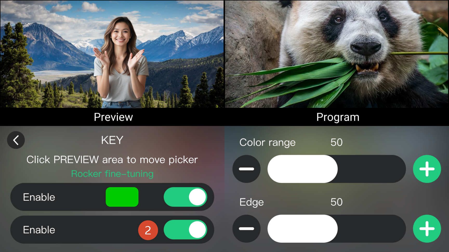
  1. Enable the chroma key function (see โ‘ก) to apply the effect.

Enable chroma key

  1. Use the + and - buttons to adjust the chroma key effect.
  • Color Range: Adjusts the selected background color range. Higher values select a wider color range; lower values provide more precise selection.
  • Edge: Adjusts edge smoothness.

3.6Audio

mini-extreme ISO supports audio mixing for embedded audio, microphones, and line-level inputs.

AFV (Audio Follow Video), audio effects, and output volume control are also supported.

Audio settings can be configured from the front panel or the AUDIO menu.

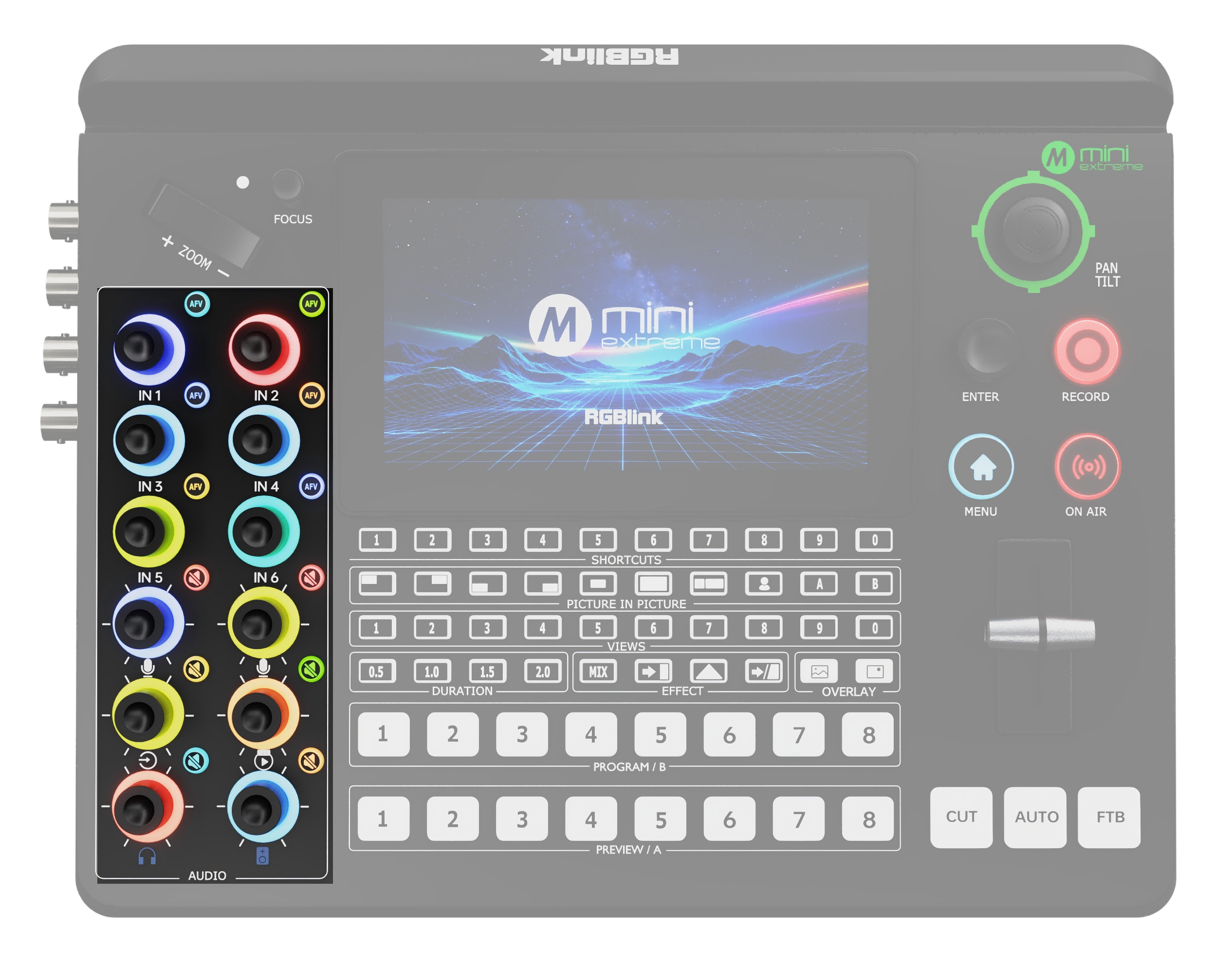
3.6.1 Front Panel Controls

Front Panel-Volume Control Example

IconDescription
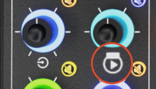
Audio Follow Video. Automatically switches the main audio output according to the current Program source. When enabled, the embedded audio from the active Program source is output automatically. For example, when HDMI 1 is switched to Program, the embedded audio from HDMI 1 is output.
Mutes the embedded audio of the selected video source only. Other audio sources are not affected.
Controls audio from the MIC 1 and MIC 2 inputs. Supports dynamic microphones, condenser microphones, and other audio input devices.
Controls audio from the Line-in input. Used for line-level signals from computers, smartphones, mixers, or audio players.
Adjusts monitor output volume. Does not affect Program output volume.
Adjusts the main output volume used for recording, streaming, and live sound reinforcement.
Adjust the volume of the UVC input sources on IN 7/IN 8

3.6.2 Audio Source Management

Go to MENU > AUDIO to view and manage all audio sources.

Audio Management Example

IconDescription
IN 1-4Embedded audio from HDMI 1 -4
IN 5Embedded audio from SDI 1 or SDI 2
IN 6Embedded audio from SDI 3 or SDI 4
IN 7UVC Audio
IN 8NDI Audio
MIC 1Microphone input 1
MIC 2Microphone input 2
LINE-INLine-level input

Embedded Audio Mixing

Embedded audio refers to audio extracted from HDMI and SDI inputs.

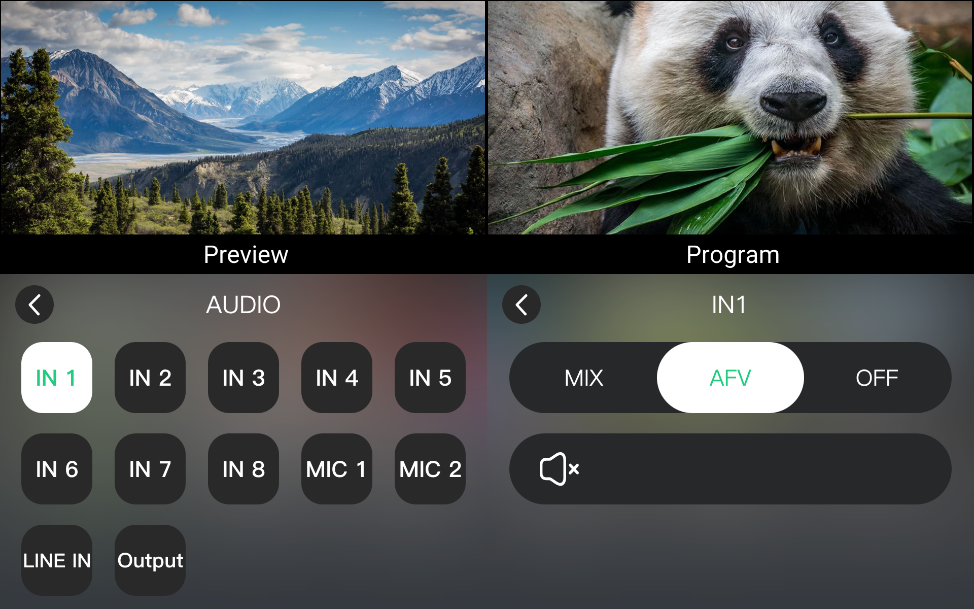
  1. Press MENU.
  2. Select Audio.
  3. Select IN1โ€“IN6.
  4. Set the mode to MIX, AFV, or OFF.

Embedded Audio Management Example

Each embedded audio source supports the following modes:

ModeDescription
MIXIncludes the audio source in the main mix.
AFVAudio follows AFV switching.
OFFExcludes the audio source from the main mix.

MIC and Line-in Input

๐Ÿšจ  Attention

Enable 48 V Phantom Power before using a condenser microphone that requires phantom power.  

mini-extreme ISO supports MIC 1, MIC 2, and Line-in inputs. Input levels can be adjusted independently.

  1. Go to MENU > AUDIO.
  2. Select MIC 1, MIC 2, or LINE IN.
  3. Click โš™.
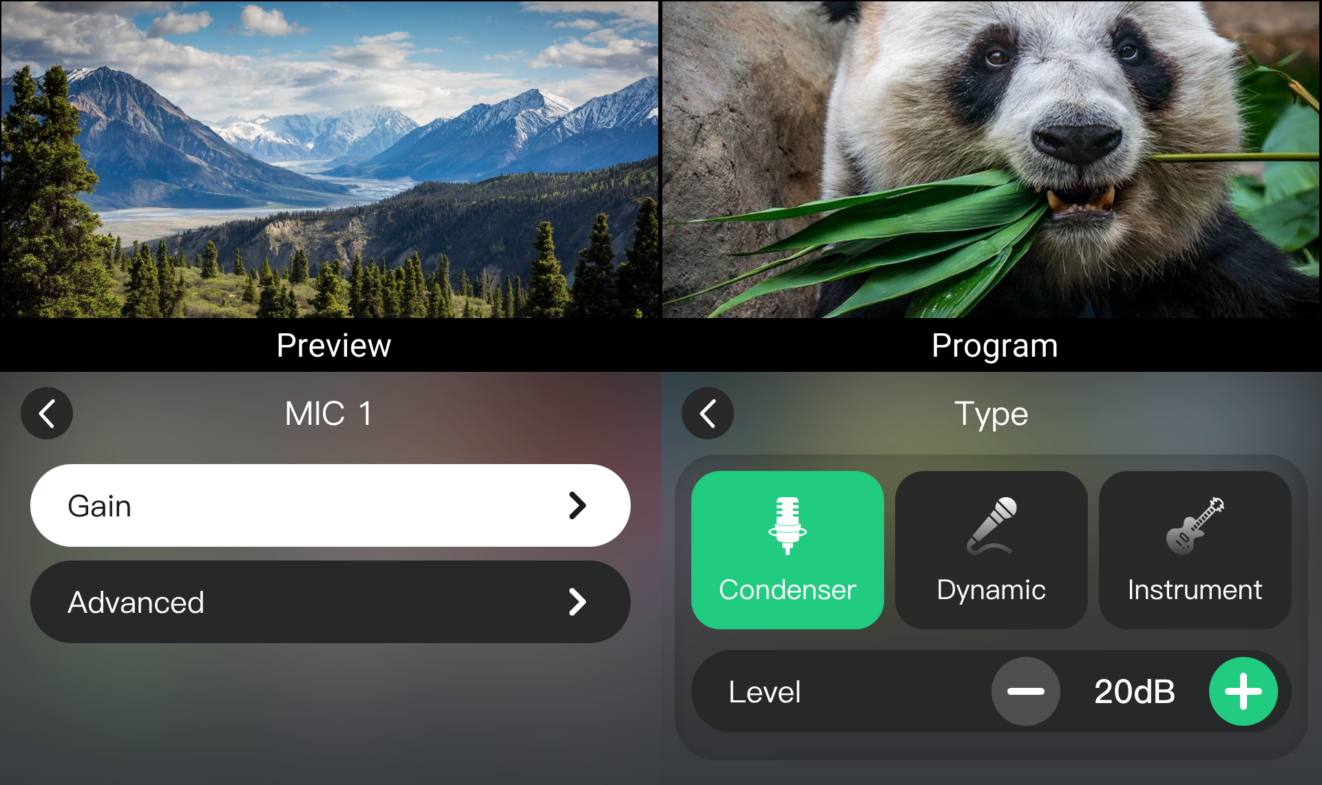
  4. Select Gain.
  5. Select the input device type, then use + or โˆ’ to adjust the level.
๐Ÿ‘‰

Line-in Input

The 6.35 mm Line-in port provides unbalanced stereo audio input. The default input gain is 0 dB.

Adjust the volume and gain according to the input signal level.

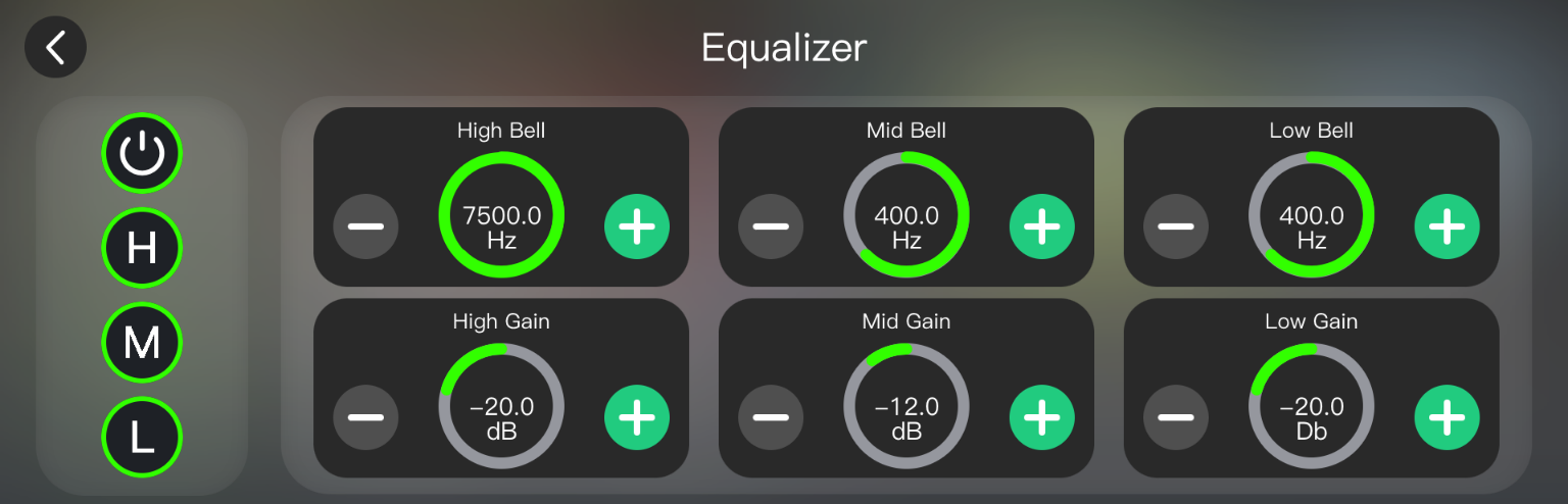
3.6.3 Advanced

mini-extreme ISO supports real-time audio processing.

  1. Go to MENU > AUDIO.
  2. Select the desired audio source and choose Advanced settings.
  3. Click the required effect icon.
๐Ÿ‘‰
  1. Use + or โˆ’ to adjust parameters.
  2. Supported audio effects:
Noise ReductionEqualizerEchoReverbVoice Fusion
MIC 1 and MIC 2โˆšโˆšโˆšโˆšโˆš
LINE INร—โˆšโˆšโˆšโˆš

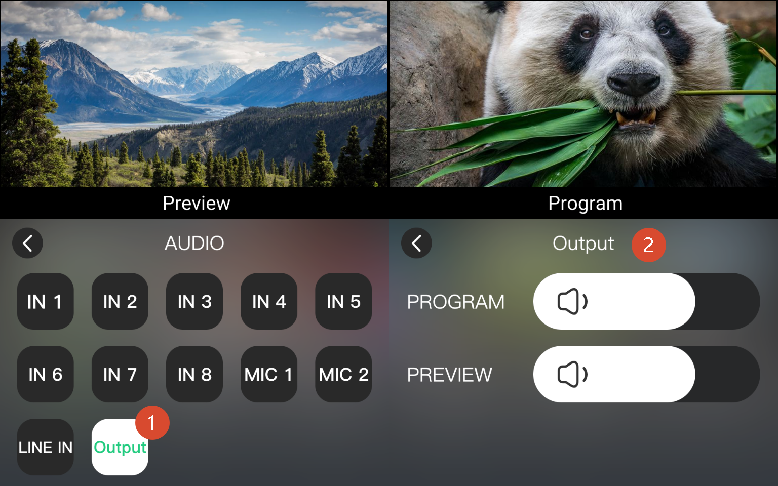
3.6.4 Output Volume

mini-extreme ISO provides two audio outputs. Use the volume sliders to adjust the output level.

OutputDescription
PROGRAMMain output containing the final audio mix
Multi-viewMonitor output for local monitoring only.
๐Ÿ“ข  Notes

Adjusting the monitor volume does not affect the Program output volume.  

3.7Transition Effects

mini-extreme ISO provides multiple transition effects. Select different effects and durations to create smoother scene changes.

3.7.1 Selecting a Transition Effect

Select a transition effect in either of the following ways:

  • Use the EFFECT buttons on the front panel for quick access to 4 commonly used effects.

Front Panel EFFECT Buttons

  • Navigate to MENU > EFFECT.

3.7.2 Transition Effect Descriptions

The following effects are supported:

Cut

The Source 1 switches to Source 2 instantly with no transition effect.

๐Ÿ‘‰

Mix

During the transition, Source 1 gradually fades out while Source 2 gradually fades in, blending together smoothly.

๐Ÿ‘‰

Right to Left Wipe

Source 2 wipes from right to left over Source 1 until the transition is complete.

๐Ÿ‘‰

Left to Right Wipe

Source 2 wipes from left to right over Source 1 until the transition is complete.

๐Ÿ‘‰

Bottom Up Wipe

Source 2 wipes upward over Source 1 until the transition is complete.

๐Ÿ‘‰

Top Down Wipe

Source 2 wipes downward over Source 1 until the transition is complete.

๐Ÿ‘‰

Venetian Blinds Right

Source 2 appears in vertical strips expanding horizontally from the center, creating a venetian blinds transition effect.

๐Ÿ‘‰

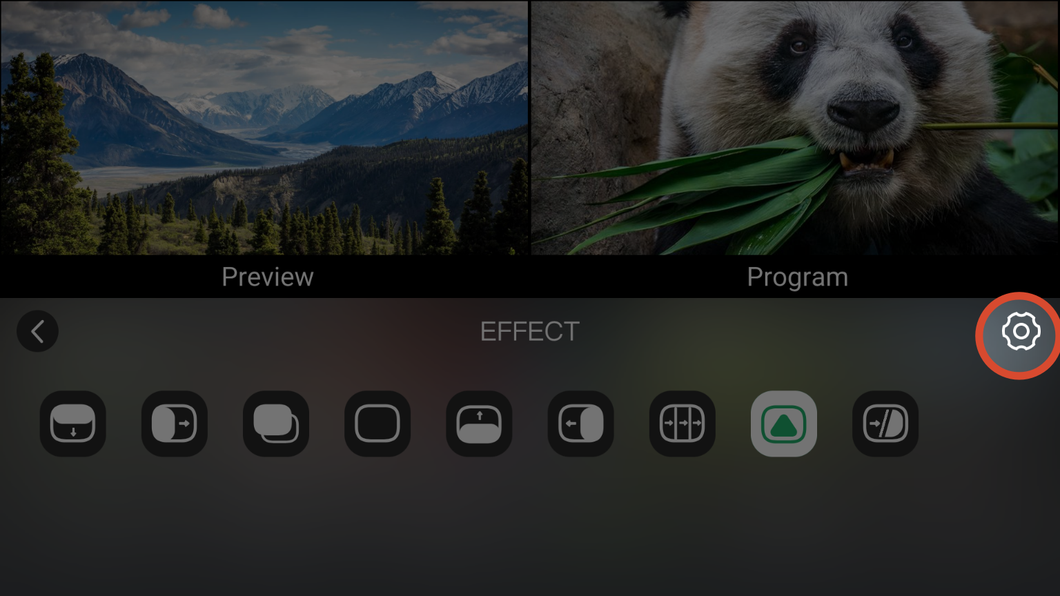
Dip

Dip supports using image files as transition frames.

When this effect is enabled, Source 1 gradually fades to the selected image, then transitions from the image to Source 2.

๐Ÿ‘‰

Dip Settings

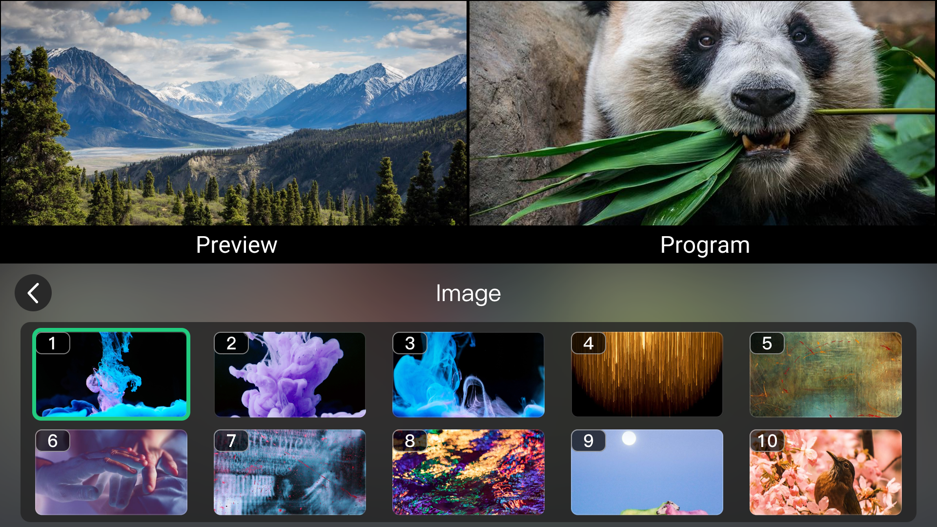
  • Rename PNG image files as image1, image2, image3, and so on. Set the image size according to the output resolution.
  • Store the image files in the mini extreme/image folder on the device disk.
  • Click the Dip icon.
  • Click the Settings icon โš™ in the upper-right corner to open the image library.
  • Select the required image as the Dip effect source.
๐Ÿ‘‰

Merge

Blends two video sources together to create a soft compositing effect.

๐Ÿ‘‰

3.7.3 Setting the Transition Duration

Use the DURATION controls on the front panel to adjust the transition duration.

The duration is measured in seconds.

Longer durations create smoother and more gradual transition animations.

DURATION Buttons on Front Panel

3.8Switching Modes

Swtiching modes controls how the Preview image transitions to Program.

mini-extreme supports CUT, AUTO, FTB, and T-bar modes to suit different production requirements.

Switching Controls on Front Panel

ModesDescription
CUTInstantly switches Preview to Program without a transition effect.
AUTOTransitions from Preview to Program automatically using the selected effect and duration. By default, mini-extreme uses a 1.0-second Mix transition.
FTBThe image gradually fades to black.
T-barUse the front panel T-bar to control the progression and speed manually.
๐Ÿ“ข  Notes

Configure the transition effect and duration used by AUTO mode in MENU > EFFECT. 
See chapter 3.7 Transition Effects for details.

3.9Views

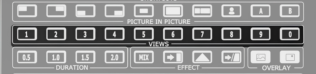
The VIEWS function saves and restores device configurations.

Save layouts, inputs, PTZ presets and effects as a view, then recall them instantly when needed.

Each saved view stores the current configuration, including layout settings, input assignments, PTZ camera presets, chroma key settings, and so on.

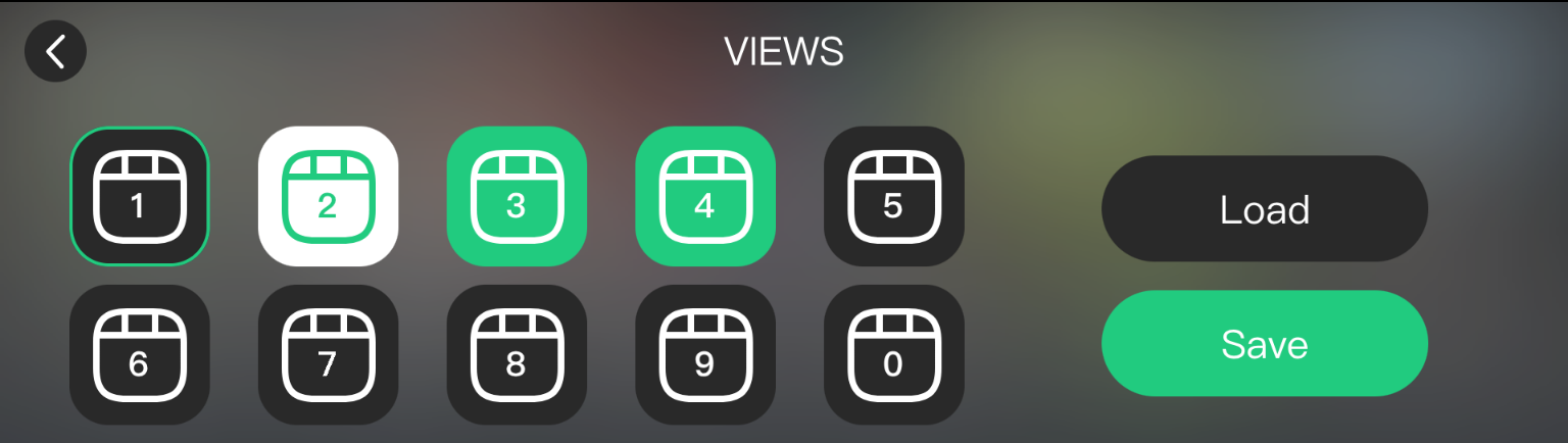
3.9.1 Views Status

Views List on the Touchscreen

Views Status Example

StatusDescription
BlackEmpty view slot.
WhiteSelected view slot.
GreenSaved view.
VIEWS Buttons on the Front Panel

Front Panel VIEWS Buttons

Indicators Example

StatusDescription
OffEmpty view slot.
Solid GreenSaved view.
Solid RedView is loading to Preview.

3.9.2 Saving or Replacing a View

Saving a view records the current device configuration.

If the selected view slot already contains a saved view, the new view replaces the existing one.

Saving from the Touchscreen:
  1. Complete the required configuration.
  2. Go to MENU > VIEWS.
  3. Set the operation mode to Save.
  4. Select a view slot.
  5. Tap the view slot twice.
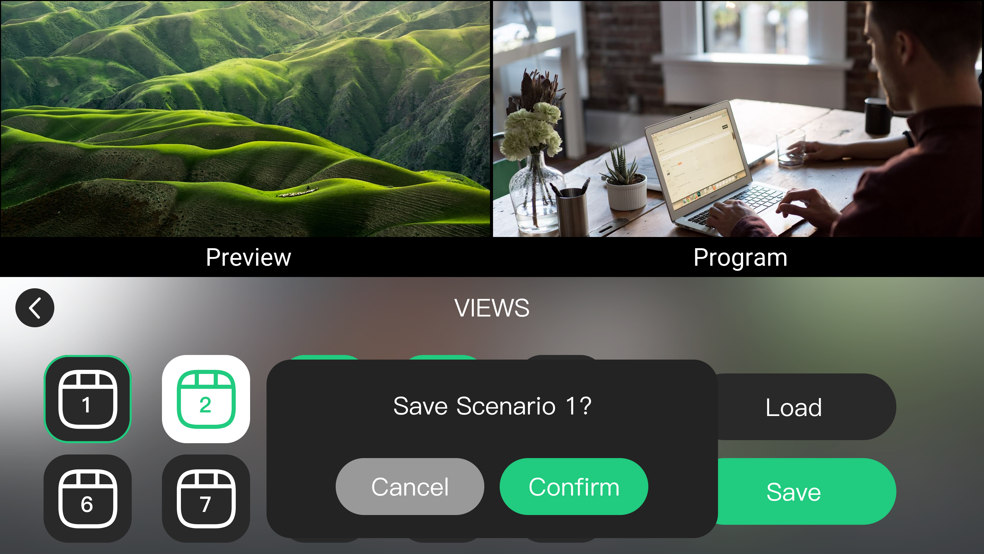
  6. Confirm the operation in the dialog box.
Saving from the Front Panel:
  1. Complete the required configuration.
  2. Press and hold the corresponding number button in the VIEWS section.
  3. Confirm the operation in the dialog box.

Dialog Box Example

๐Ÿ“ข  Notes

- If the selected slot is empty, mini-extreme creates a new view.
- If the selected slot already contains a saved view, mini-extreme  replaces it.

3.9.3 Load a View

Loading a view restores a saved configuration without reconfiguring layouts, input sources, or image effects.

Loading from the Touchscreen:
  1. Go to MENU > VIEWS.
  2. Set the operation mode to Load.
  3. Select the view to load.
Loading from the Front Panel:
  1. Press the number button corresponding to a saved view in the VIEWS section.
  2. Load the view to the Preview window.
๐Ÿ“ข  Notes

Loading a view restores all saved parameters, including layout settings, input assignments, PTZ presets, and image effect settings.

3.10Streaming

mini-extreme ISO supports the following streaming methods:

  • Streaming on Device
  • NDI Streaming
  • USB Port Capture and Output
  • โ€ฆโ€ฆ

Choose the method that best fits your production workflow.

Before using the streaming function, make sure mini is connected to the network. Connect the device to a router or network switch using an Ethernet cable.

RGBlink CAT6 Ethernet cables are recommended. Product code: 940-0001-00-11-0

๐Ÿ“ข  Notes

1. When streaming to multiple platforms simultaneously, a gigabit internet connection is recommended for optimal performance and stability.  
2. For multi-platform streaming, the TAO Cloud distribution service is recommended.

3.10.1 Obtaining the Stream URL and Stream Key

๐Ÿšจ   Risk Warning

Do not share your stream key with anyone or display it during a live stream. Doing so may result in unauthorized account access, stream hijacking, or other potential risks and losses.

If your stream key is exposed:

-  Immediately reset the stream key on the corresponding platform.
-  Stop the current live stream.
-  Restart streaming using the new stream key.

View Streaming to Live Platforms to check how to get stream key from other platforms.

3.10.2 Streaming on Device

mini-extreme ISO supports standalone live streaming without a computer or mobile device.

Up to 4 destinations can be streamed simultaneously from a single device.

Configuring Streaming in Web App

  1. Log in to Web App as described in chapter 3.1 Operation.
  2. Go to MENU > OUTPUT > Stream.
  3. Paste the stream URL into the streaming configuration field.
  4. Click Distribute to send the configuration to the device.
  5. Press ON AIR on the front panel, or enable ON AIR in Web App.

The ON AIR indicator lights up when streaming starts.

Importing a Stream URL from a USB Drive

  1. Create MINI_EXTREME_RTMP.ini in the root directory of a USB drive.
  2. Add the stream URL to the file.
  3. Connect the USB drive to USB-C 1.
  4. Wait for the device to load the streaming configuration.
  5. Press ON AIR to start streaming.

Configuring Streaming Through TAO Cloud

  1. Log in to TAO Cloud and complete device binding as described in chapter 3.15 TAO Cloud.
  2. Go to My Collection > Device and open the device management page.
  3. Paste the streaming address and stream key into TAO Cloud, then click Distribute.

3.10.3 NDI Encoder

mini-extreme ISO can encode the Program output as an NDI stream and distribute it over the local network.

Enable NDI code in OUTPUT > Stream. NDI-compatible devices on the same network can then receive the Program output directly.

  • NDI output resolution matches the Program output resolution.
  • Maximum NDI output bitrate: 32 Mbps.
  • The device appears in NDI Tools as RGBLINK (mini-extreme-Local IP Address).
๐Ÿ“ข  Notes

When IN 7 or IN 8 is configured as a UVC or NDI input, set the NDI output resolution to 3840 ร— 2160@30 or lower for more stable performance.  

3.10.4 USB 2 Port Capture and Output

mini-extreme ISO can also be connected to a computer through USB2 and used as a video source for third-party streaming software such as OBS Studio.

The following examples use OBS Studio for demonstration.

  • Download OBS from: OBS Studio. Install the software and update it to the latest version before use.
  • Open OBS, add a Video Capture Device.
  • Select RGBlink USB3.0 Capture, and select YUY2 for the Video Format.

Audio Settings

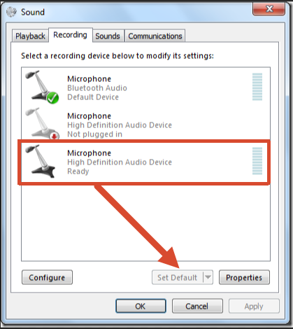
If no audio is detected during streaming:

  1. Confirm the audio source on the device is configured correctly (Set Default).

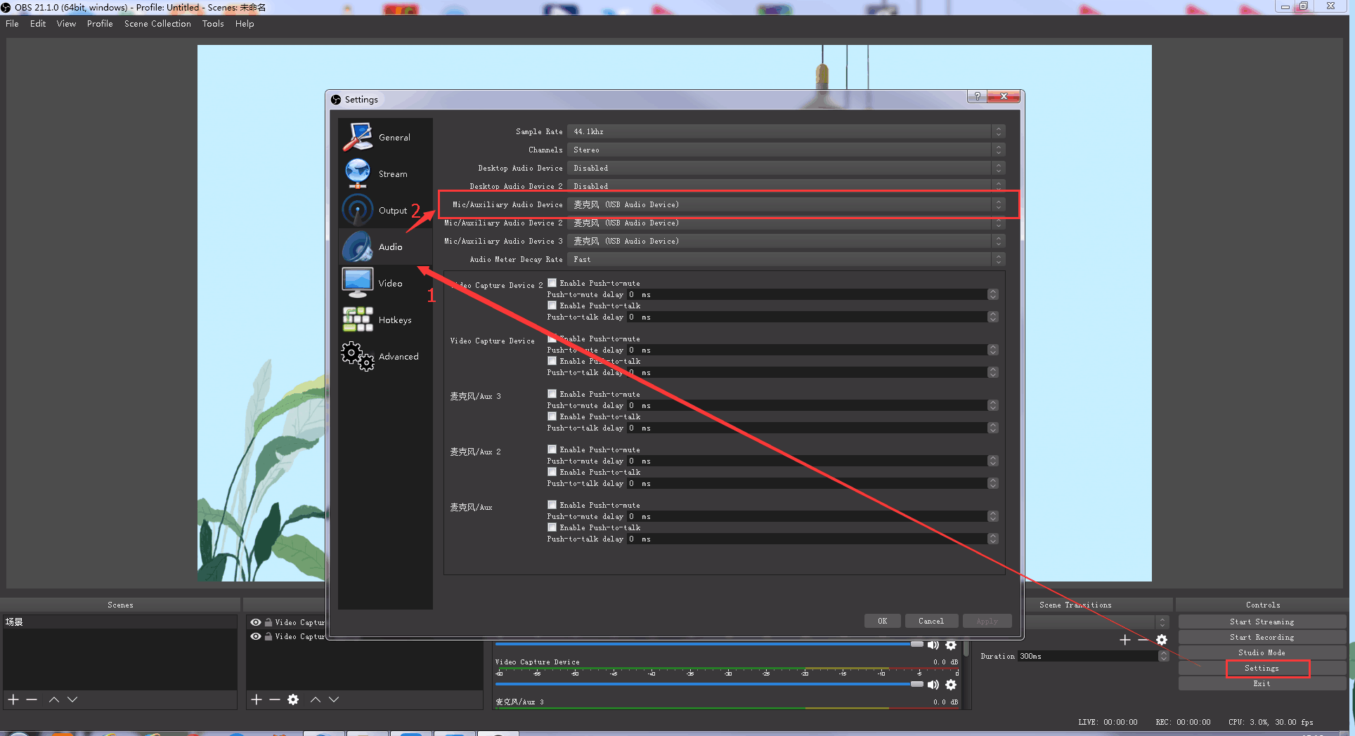
  1. In OBS, go to Settings > Audio. Select the correct device Mic/Auxiliary Audio Device.

Synchronize Video with External Audio

If the video source does not contain embedded audio and external audio is used separately, synchronize the audio and video using the following steps.

  1. Go to Settings > Audio > Mic/Auxiliary Audio Device and select the audio source.

  1. In the Sources panel, right-click Video Capture Device, then select Filters.

  1. Under Audio/Video Filters, click + and select Video Delay (Async).

  1. Enter a filter name if needed, then click OK.

  1. synchronous.Enter the delay value in milliseconds (ms).
    Adjust the value until the audio and video are synchronized.

Streaming Settings

  1. Obtain the RTMP URL and Stream Key from the streaming platform.
  2. Copy the RTMP URL and Stream Key.
  3. In OBS, go to Settings > Stream.
  4. Select the streaming type:
  • Streaming Service
  • Custom Streaming Server

If the platform is listed under Service, select it directly.

If using a custom server:

  • Enter the RTMP URL in Server/URL

  • Enter the Stream Key in Stream Key
  1. Click Start Streaming.
  2. Return to the streaming platform and confirm the live stream is active

3.11Recording

mini-extreme ISO supports recording the program output directly through a USB storage device.

In addition to UVC camera input and asset import, USB-C 1 supports storage devices for local recording, providing recording backup for live streaming, meetings, and content production.

Use a USB flash drive or SSD for recording. SSD is recommended for multi-channel recording.

  1. Connect a USB flash drive or SSD to USB-C 1.

  1. Select MENU > OUTPUT > Record to open the recording settings page.

Record Page Example

  1. The device automatically detects the storage status and displays:
  • Remaining recording time
  • Disk information
  • The RECORD button lights white

3.11.1 Recording Capability

mini-extreme ISOsupports recording one fixed Program output (PGM) and up to three input sources simultaneously.

Selecting PVW (Preview) or AUX outputs as the recording source is not supported.

ISO recording allows separate recording of the PGM output and input sources. Each source generates an independent recording file.

The factory default setting enables one PGM recording channel:

  • Resolution: 3840 ร— 2160@60
  • Bitrate: 8 Mbps

To record additional input sources, adjust the recording resolution and bitrate for PGM and each input source in OUTPUT > Record > Configuration.

The recording resolution follows the input source resolution. If the input source is 1080p, the recorded video will also be 1080p. The device does not upscale the video to a higher resolution.

Record Configuration Example

๐Ÿ“ข  Notes
When recording multiple input sources, lower the PGM output resolution to 2K@60 to select up to 3 input sources for recording.

Higher bitrates provide better recording quality but require more storage space.

Recording Channels (including one FIXED PGM)Maximum Supported Specification
Single-channel recording1 ร— 4K@60 PGM
Dual-channel recording1 ร— 4K@30 PGM + 1 ร— 4K@30 IN
Three-channel recording1 ร— 4K@30 PMG + 2 ร— 2K@60 IN
Four-channel recording1 ร— 2K@60 PGM + 3 ร— 2K@60 IN
๐Ÿ“ข  Important
No supported mini model allows users to configure the PGM and UVC output source independently.

3.11.2 Start Recording

After confirming the status is normal, press the RECORD button on the front panel, or click the recording button โบ on the recording settings page.

When recording starts:

  • The RECORD button changes from white to red.
๐Ÿ‘‰
  • The recording page displays recording duration and status information. The main interface and multiview screen also display the recording status.

3.11.3 Stop Recording

๐Ÿšจ  Risk of Recording File Loss

After stopping a recording, wait until the file-saving process is complete before disconnecting the storage device.

Removing the storage device during recording may result in file corruption or recording failure.

  • Press the RECORD button again to stop recording.
  • After recording stops, the RECORD button changes from red back to white.

3.11.4 Disk Format

The recording device must use the exFAT format.

If the format is incompatible, format the storage device on a Windows computer:

  • File system: exFAT
  • Allocation unit size: 128 KB

After formatting, confirm disk formatting from the recording page on mini-extreme ISO.

Record Page Example-Disk Format

๐Ÿ“ข  Notes
- Recording files are automatically split into 4 GB segments. 
- For 2K@60 recording, set the corresponding input source resolution to 2K.
- Multi-channel recording requires high storage read/write performance. An SSD is recommended.  

3.12Controlling PTZ Camera

mini-extreme supports PTZ camera control via IP VISCA and NDI protocols.

Control PTZ camera pan, tilt, zoom, and focus from mini-extreme. Save frequently used positions for quick recall.

  • Supports up to 8 PTZ cameras simultaneously.
  • Supports saving PTZ presets.
  • Supports saving PTZ parameters with the VIEWS function.

3.12.1 Connecting PTZ Cameras

Before controlling PTZ cameras, complete network connection and communication settings.

  • mini-extreme and PTZ cameras must be on the same network segment.
  • Use a network switch for connection.
Connecting One PTZ Camera

Recommended connection:

  1. Connect the switch to the router.
  2. Connect mini-extreme to the switch using an Ethernet cable.
  3. Connect the PTZ camera to the switch using an Ethernet cable.

You can also connect mini-extreme directly to the PTZ camera using an Ethernet cable.

๐Ÿ“ข  Notes

When using a direct Ethernet connection, mini-extreme cannot access external networks. Use this method only when no switch is available.  

Connecting Multiple PTZ Camera

mini-extreme supports controlling up to 8 PTZ cameras through a network switch.

  1. Use the ping command to check network connectivity and confirm whether the IP address is available.
  • Press Windows + R.
  • Enter cmd and click OK.
  • In Command Prompt, enter a command such as ping 192.168.5.66

If the message Destination Host Unreachable is displayed, the address is not currently in use.

Assign the available IP address to the PTZ camera and run the ping command again.

If a reply is received, communication between mini-edge SDI and the PTZ camera has been established successfully.

  1. Configure Camera IP Addresses

Ensure that:

  • Each camera uses a unique IP address.
  • All devices are on the same subnet as mini-extreme.
  1. Connect the Network Switch
    1. Connect the switch to the router.
    2. Connect mini-extreme to the switch using an Ethernet cable.
    3. Connect up to 8** **PTZ cameras to the switch using Ethernet cables.
RGBlink CAT6 Ethernet cables are recommended. Product code: 940-0001-00-11-0
  1. mini-extreme can now control multiple PTZ cameras simultaneously (up to 8).
๐Ÿ“ข Notes

1. Ensure that the computer, mini-extreme, and all PTZ cameras are on the same subnet. 
2.  Verify each camera IP address individually using the **ping** command. 
3.  mini-extreme supports: 
-  IP VISCA 
-  NDI Control 

The following protocols are not currently supported:
-  CGI 
-  HTTP 
-  Pelco-D 
-  Pelco-P

Configuring IP Address and Port
๐Ÿ“ข  Notes

mini-extreme communicates with cameras through ports.

RGBlink Vue series broadcast cameras use port 1259 by default. For other camera brands, check the camera manual and enter the correct port number.

  1. Navigate to MENU > PTZ.

  1. Select the arrow icon > in the upper-right corner to switch to the second page.
PTZ Page 1 ExamplePTZ Page 2 Example
๐Ÿ‘‰
  1. Click + or โˆ’ in the IN section to switch the Preview screen to the corresponding PTZ input source.
  2. Use the front-panel ENTER button to set the camera IP address and port. Ensure the camera and mini-extreme are on the same network segment.
๐Ÿ“ข  Notes

- A green border indicates selection mode. You can switch between digits but cannot edit values.
- A blue border indicates edit mode. You can modify the selected digit.

a. Press ENTER to enter selection mode.

b. Rotate the knob left or right to select the digit to edit.

c. Press ENTER again to enter edit mode.

d. Rotate the knob left or right to adjust the value.

e. Repeat steps bโ€“d to complete IP address or port editing.

f. Press ENTER again to exit edit mode and save settings.

3.12.2 Controlling PTZ Cameras

PTZ control adjusts camera position, zoom, and focus.

Using the Front Panel

Adjusting Zoom:

  • Rotate the ZOOM controller to adjust focal length.

Adjusting Focus:

  • Press the FOCUS knob to enable autofocus.
  • Rotate the FOCUS knob to adjust focus manually.

Adjusting Pan/Tilt Position:

  • Move the 5-Direction Joystick to control camera movement.
  • Press the 5-Direction Joystick to return to the initial position.
Using the Touchscreen
  1. Navigate to MENU > PTZ.
  2. The following controls are available:
FunctionDescription
ZoomAdjusts lens zoom and restores the previous setting with one click.
FocusAdjusts focus position and enables or disables autofocus.
PositionTap the arrows to adjust pan and tilt direction.
SpeedSelect the number button in the center of the Location area, then tap the screen or press ENTER to adjust pan/tilt speed. Supported pan/tilt speeds: 17/15/13/11/9/7/5/3/1

3.12.3 Saving and Loading a PTZ Preset

PTZ presets save the current camera position, zoom, and focus settings.

When loading a preset, the PTZ camera autimatically moves to the saved position.

Saving a PTZ Preset
  1. Adjust the camera to the desired position.
  2. Set the required zoom and focus parameters.
  3. Press and hold the corresponding scene button in the VIEWS section.
  4. Save the current PTZ preset as a View.

Front Panel VIEWS Buttons

Or:

  1. Adjust camera parameters.
  2. Open the VIEWS page.
  3. Save the current PTZ preset as a View.
Loading a PTZ Preset

Press the corresponding saved VIEWS button to load the preset.

๐Ÿ‘‰

3.13Customized Buttons

The 0โ€“9 buttons in the SHORTCUTS section on the front panel support custom function assignment.

Open the mini-extreme Web App interface and navigate to Custom Button Function.

Users can drag and drop functions onto any numeric button to create shortcuts. A single function can be assigned to multiple buttons.

Click Novice Guide in the lower-left corner of the page for a quick overview of the configuration process.

Customized Button Function Page Example

Button Status Indicators

The button editor uses the following status indicators:

Button Status Indicators Example

  • Red: Function assigned
  • Blue: Currently selected for editing
  • Number Button: No function assigned
  • ๐Ÿงน: Remove all button assignments
  • ๐Ÿ—‘๏ธ: Remove the selected button assignment

Available Functions

The following functions can be assigned to custom buttons:

  • SIGSEC (Signal Security)
  • PTZ CX (signal channel)
  • DSK BG
  • Fan Speed +
  • Fan Speed -

SIGSEC

The SIGSEC function allows the system to switch instantly to a predefined output source when required.

Available options include:

  • Security Thematic BG: One-click to realize switching to the specific backup signal in case of emergencies.
  • SIGSEC IN 1-5: PGM output SIGSEC IN 1-5 in full screen in any state.
  • Black Screen: One-click to go to black screen for Program.
  • Colorbar: Static colorbar picture.

Selecting a SIGSEC immediately switches the Program output to the configured source.

PTZ CX

PTZ CX provides quick access to a camera control interface.

After selecting an HDMI or UVC source, the corresponding PTZ control page opens automatically and PTZ control is enabled.

Users can operate the camera using the 5-Direction Joystick and focus controls on the front panel.

DSK BG

The DSK BG function allows rapid switching of background sources.

Available options include:

  • BG: Select an image stored on the device as the DSK background. Repeatedly pressing the assigned button cycles through the available background images. After the last image is reached, the sequence returns to the first image.
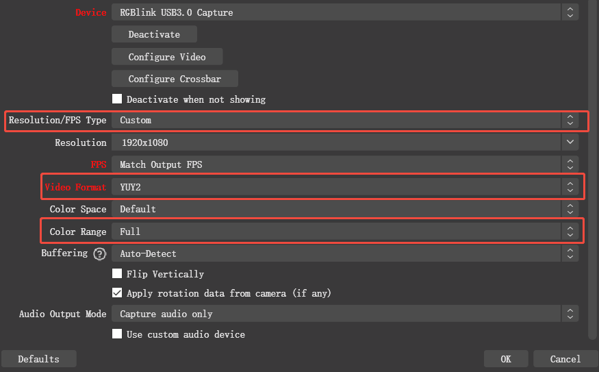
  • Preset Input: Select a input signal as the DSK background source.
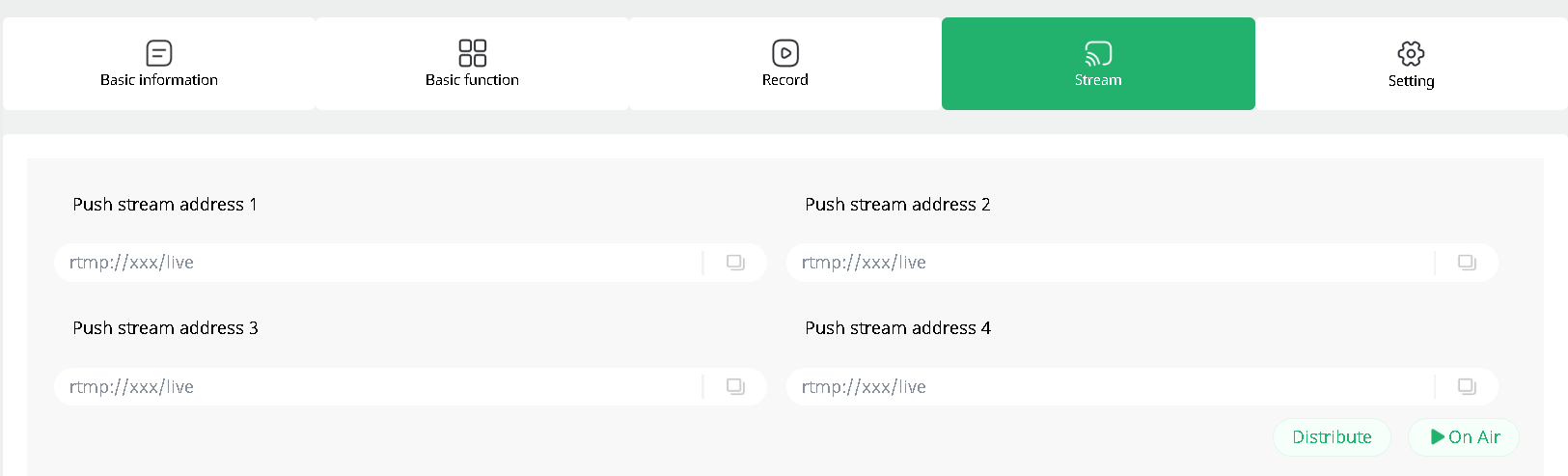
Fan Speed

Fan Speed Control allows quick adjustment of the cooling fan speed.

3.14Settings

Navigate to MENU > SETTINGS.

The Settings menu includes language selection, device information, TAO Cloud binding, IP settings, date and time settings, fan control, T-Bar calibration, key test, firmware upgrade, and factory reset.

๐Ÿ‘‰

3.14.1 Language/่ฏญ่จ€

Select the system language:

  • English
  • ็ฎ€ไฝ“ไธญๆ–‡

3.14.2 Device Version

View device information, including:

  • Serial Number (SN)
  • MAC Address
  • VIDEO Version
  • MCU Version
  • APP Version

3.14.3 TAO Cloud

Ensure the device is connected to the network.

  1. If the device is not bound to TAO Cloud, the verification code is displayed.
  2. If the device is already bound, the screen displays the linked status and associated TAO Cloud account.

3.14.4 IP Setting

mini-extreme supports wired network connections.

Default IP address: 192.168.5.100

Using DHCP
  1. Connect mini-extreme to a router or network switch using an Ethernet cable.
  2. Enable DHCP. The device automatically obtains an IP address.
Using a Static IP Address
  1. Disable DHCP.
  2. Select the IP address field.
  3. Press ENTER, then rotate the knob left or right to modify the IP address.
  4. Save the settings.
๐Ÿ“ข  Notes

When using a static IP address, avoid IP conflicts with other devices on the network.  

3.14.5 Time Setting

Automatic Time Synchronization
  1. Ensure the device is connected to the network.
  2. Enable Auto Set. The device synchronizes the time automatically.
Manual Time Configuration
  1. Disable Auto Set.
  2. Set the time zone, date, and time.
  3. Save the settings.
๐Ÿ“ข  Notes

Configure the system time manually when the device is not connected to a network.

3.14.6 Fan Speed

mini-extreme provides automatic and manual fan control modes.

Automatic Mode

Enable Auto.

The system adjusts fan speed automatically based on operating conditions.

Manual Mode
  1. Disable Auto.
  2. Click + or โˆ’ to adjust fan speed.
  • Adjustment range: 0โ€“100
  • Increment: 10
๐Ÿ“ข  Notes

Use Automatic Mode for optimal cooling performance and noise control.  

3.14.7 T-Bar Correction

T-Bar Correction restores transition position accuracy. Run correction if transition positions are inaccurate or the T-Bar travel does not match the displayed transition progress.

T-Bar Correction Page Example

  1. Push T-Bar to bottom.
  2. Enable the switch for Step 2.
  3. Push T-Bar to top.
  4. Enable the switch for Step 4.
  5. Complete the correction.

3.14.8 Button Test

ButtonTest verifies front-panel button operation.

  1. Press any button.
  2. Check whether the button displayed on screen matches the button pressed.

If the displayed result is correct, the button operates normally.

3.14.9 Update

Check whether a firmware upgrade is available.

For upgrade instructions, see chapter 4. Upgrade for details.

3.14.10 Reset

๐Ÿšจ  Warning  

Reset permanently deletes all user settings, views, and custom parameters. Deleted data cannot be recovered.  

Reset restores all settings to factory defaults.

  1. Go to SETTINGS > Reset.
  2. Click Yes in the confirmation dialog.
  3. Wait for the reset process to complete.
๐Ÿ“ข  Notes

Restart the device after completing a factory reset.  

3.15TAO Cloud

mini-extreme can be linked to the TAO Cloud platform for remote live streaming management and multi-platform content distribution.

After logging in to TAO Cloud, users can start live streams directly from the cloud and distribute content to more than 30 major streaming platforms simultaneously, improving both workflow efficiency and audience reach.

3.15.1 Linking to TAO Cloud

  1. Navigate to MENU > SETTINGS > TAO Cloud
  2. If the device has not yet been linked to TAO Cloud, a verification code will be displayed. Before obtaining the code, ensure that the device is connected to the network.

  1. Open TAO. Enter your mobile phone number, and click Send Verification Code. Enter the received code and click Log In.

  1. After logging in, navigate to: My Collection > Device > All Application > Binding Devices

Enter:

  • Device Name
  • Verification Code

Then tap Bind to complete device binding.

  1. After binding, the device status can be viewed in All Application page.

3.15.2 Unbind the Device

From the TAO Cloud page on the device:

  1. Select Relink.
  2. Confirm.

The current device association will be removed.

๐Ÿ“ข  Notes

If the device remains connected to the network, performing a factory reset will automatically remove its association with the TAO Cloud platform.  

3.15.3Importing Streaming Information via TAO Cloud

  1. Log in to TAO Cloud and complete device binding.

Make sure the network connection remains stable while receiving the verification code.

  1. Paste the streaming address and stream key into TAO Cloud, then click Distribute.

  1. Navigate to OUTPUT > Stream.
  2. The device displays all detected streaming destinations.
  3. Enable the platforms you want to use.
๐Ÿ‘‰

3.15.4 TAO Cloud Multi-Platform Streaming

See Live Broadcast Room for details.

4Upgrade

๐Ÿšจ   Upgrade Notice

Do not power off the device during the update. Doing so may prevent the device from starting properly.

mini-extreme ISO supports online upgrade.

Before You Begin

  1. Connect mini-extreme to your computer using an Ethernet cable.

  1. Open the network settings on your computer and ensure that both the computer and the device are on the same local network. DHCP is recommended to allow automatic IP address assignment and ensure proper communication.

Steps

  1. Navigate to MENU > SETTINGS > Update
  2. If no update is available, the screen displays a message indicating that the current version is up to date.
  3. If a new version is available, the screen displays the new version number. Click Upgrade to download and install the update.

  1. The download typically takes approximately 10 minutes, depending on network conditions.
  2. Once the upgrade is complete, the device will restart automatically.
  3. After the device restarts, return to the Update page to verify the updated firmware version.

5FAQ

Need help?

Choose one of the following support options:

  • AI Support Search (Recommended): Visit Support > Support For Individual on the RGBlink official website and ask the RGBlink AI Bot for quick answers to your questions.
  • FAQs: Visit Support > Support For Individual on the RGBlink official website and browse Knowledge Menu > FAQ for relevant information.
  • Contact Technical Support: Visit this manual, Technical Support page for our contact details.

Document image

7Revision History

VersionDateDescriptionAuthor
V1.12026-10-231. Rename to mini-extreme ISO; 2. Update 3.13 Customized ButtonsZYL
V1.02026-09-29First release.ZYL

3.8Declarations

FCC/Warranty

Federal Communications Commission (FCC) Statement

This equipment has been tested and found to comply with the limits for a class A digital device, pursuant to Part 15 of the FCC rules. These limits are designed to provide reasonable protection against harmful interference when the equipment is operated in a commercial environment. This equipment generates, uses, and can radiate radio frequency energy and, if not installed and used in accordance with the instruction manual, may cause harmful interference to radio communications. Operation of this equipment in a residential area may cause harmful interference, in which case the user will be responsible for correcting any interference.

Guarantee and Compensation

RGBlink provides a guarantee relating to perfect manufacturing as part of the legally stipulated terms of guarantee. On receipt, the purchaser must immediately inspect all delivered goods for damage incurred during transport, as well as for material and manufacturing faults. RGBlink must be informed immediately in writing of any complains.

The period of guarantee begins on the date of transfer of risks, in the case of special systems and software on the date of commissioning, at latest 30 days after the transfer of risks. In the event of justified notice of compliant, RGBlink can repair the fault or provide a replacement at its own discretion within an appropriate period. If this measure proves to be impossible or unsuccessful, the purchaser can demand a reduction in the purchase price or cancellation of the contract. All other claims, in particular those relating to compensation for direct or indirect damage, and also damage attributed to the operation of software as well as to other service provided by RGBlink, being a component of the system or independent service, will be deemed invalid provided the damage is not proven to be attributed to the absence of properties guaranteed in writing or due to the intent or gross negligence or part of RGBlink.

If the purchaser or a third party carries out modifications or repairs on goods delivered by RGBlink, or if the goods are handled incorrectly, in particular if the systems are commissioned operated incorrectly or if, after the transfer of risks, the goods are subject to influences not agreed upon in the contract, all guarantee claims of the purchaser will be rendered invalid. Not included in the guarantee coverage are system failures which are attributed to programs or special electronic circuitry provided by the purchaser, e.g. interfaces. Normal wear as well as normal maintenance are not subject to the guarantee provided by RGBlink either.

The environmental conditions as well as the servicing and maintenance regulations specified in this manual must be complied with by the customer.

Operators Safety Summary

The general safety information in this summary is for operating personnel.

Do Not Remove Covers or Panels

There are no user-serviceable parts within the unit. Removal of the top cover will expose dangerous voltages. To avoid personal injury, do not remove the top cover. Do not operate the unit without the cover installed.

Power Source

This product is intended to operate from a power source that will not apply more than 230 volts rms between the supply conductors or between both supply conductor and ground. A protective ground connection by way of grounding conductor in the power cord is essential for safe operation.
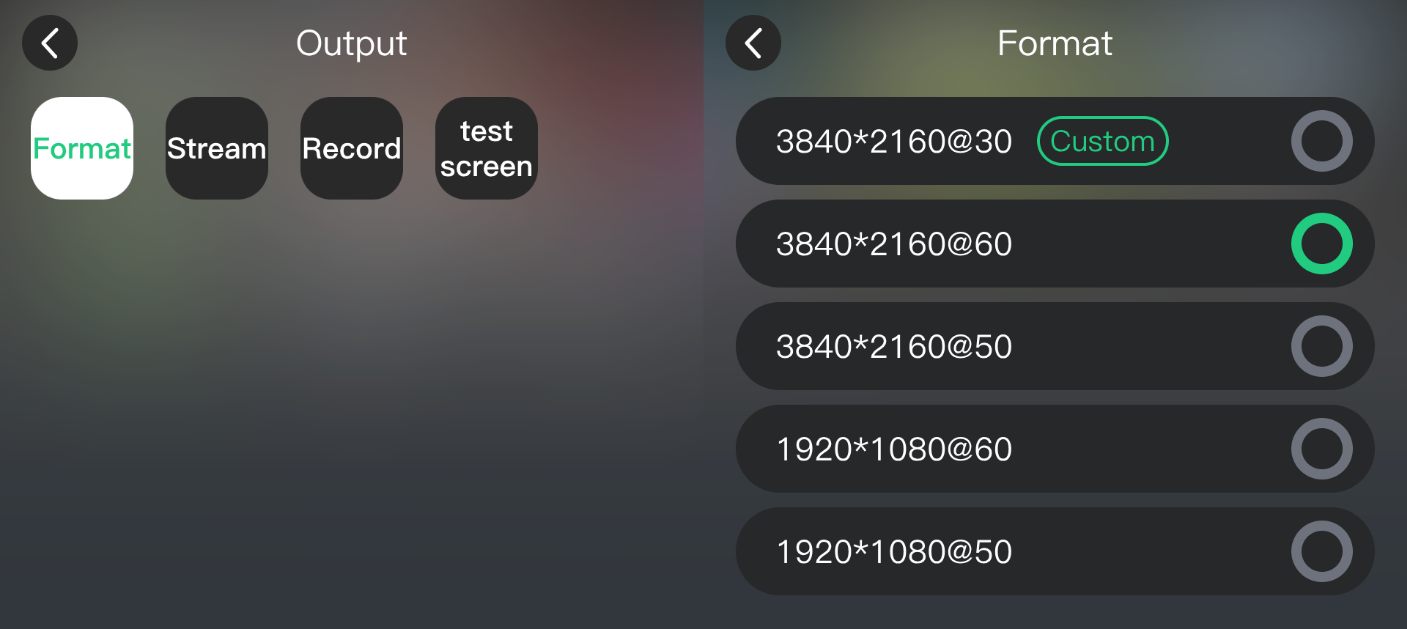
Grounding the Product

This product is grounded through the grounding conductor of the power cord. To avoid electrical shock, plug the power cord into a properly wired receptacle before connecting to the product input or output terminals. A protective-ground connection by way of the grounding conductor in the power cord is essential for safe operation.
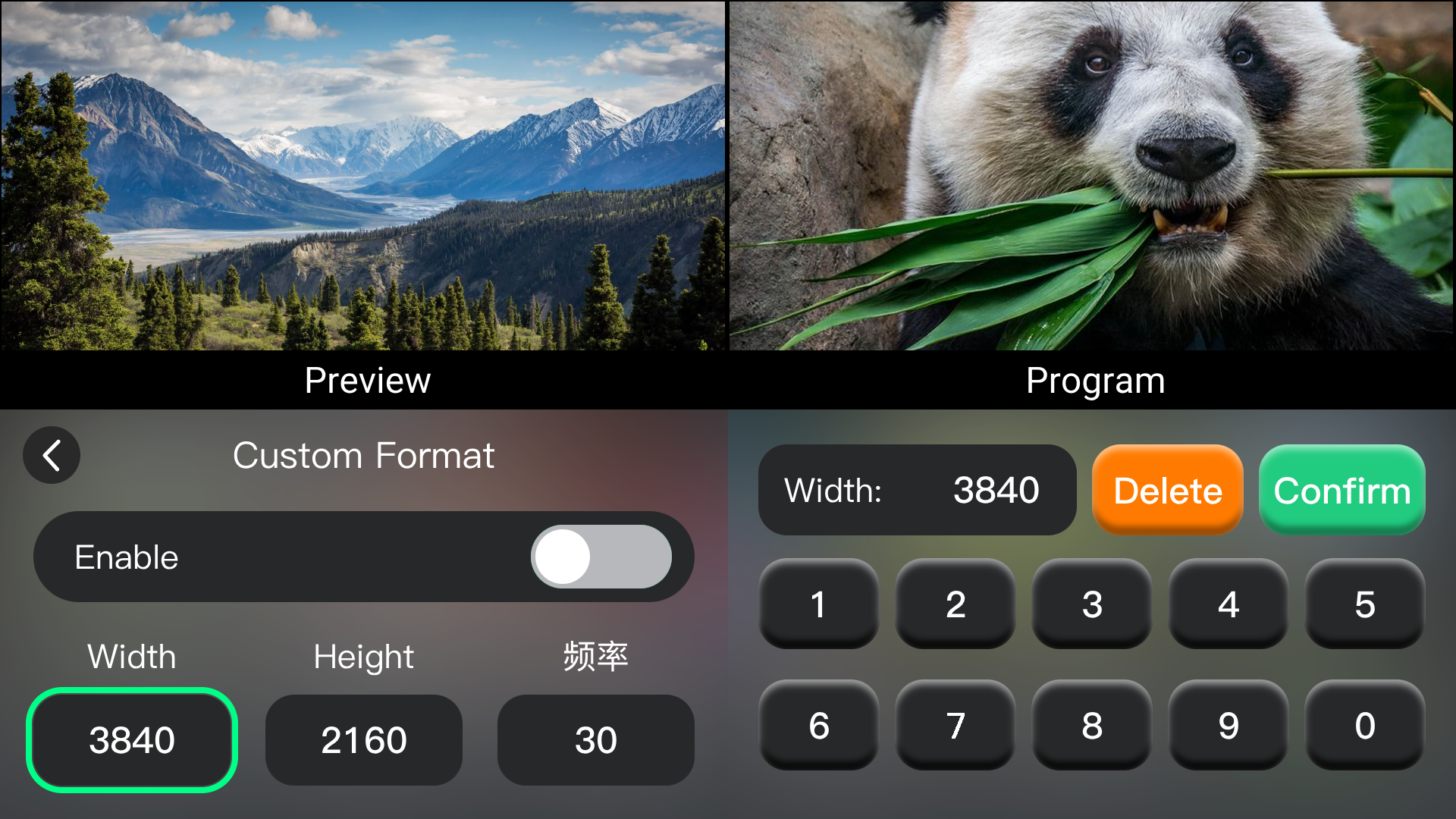
Use the Proper Power Cord

Use only the power cord and connector specified for your product. Use only a power cord that is in good condition. Refer cord and connector changes to qualified service personnel.

Use the Proper Fuse

To avoid fire hazard, use only the fuse having identical type, voltage rating, and current rating characteristics. Refer fuse replacement to qualified service personnel.

Do Not Operate in Explosive Atmospheres

To avoid explosion, do not operate this product in an explosive atmosphere.

Installation Safety Summary

Safety Precautions

For all product installation procedures, please observe the following important safety and handling rules to avoid damage to yourself and the equipment.

To protect users from electric shock, ensure that the chassis connects to earth via the ground wire provided in the AC power Cord.
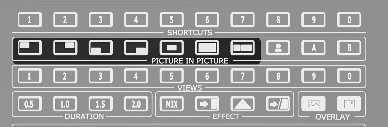
The AC Socket-outlet should be installed near the equipment and be easily accessible.
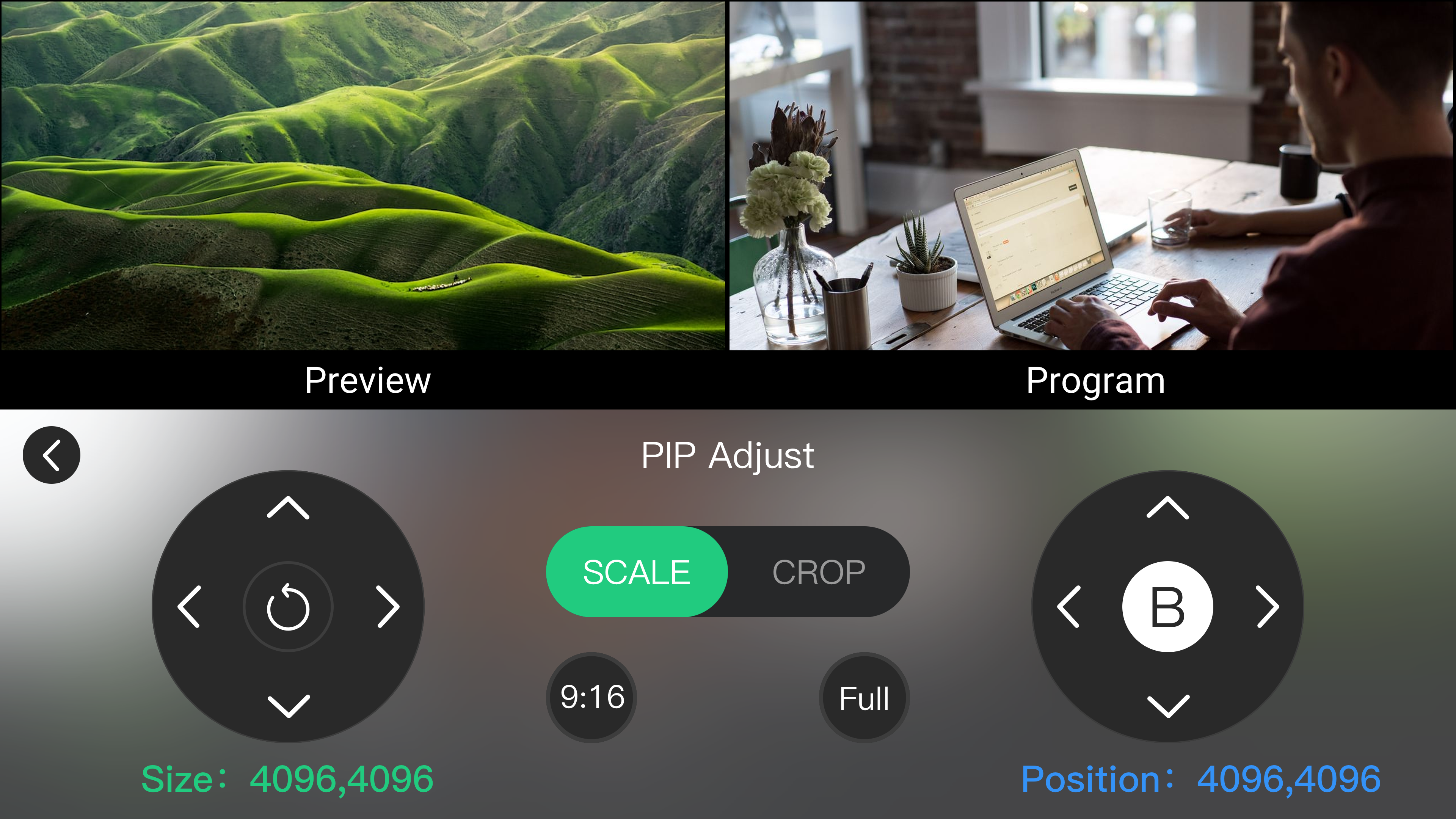
Unpacking and Inspection

Before opening product shipping box, inspect it for damage. If you find any damage, notify the shipping carrier immediately for all claims adjustments. As you open the box, compare its contents against the packing slip. If you find any shortages, contact your sales representative.

Once you have removed all the components from their packaging and checked that all the listed components are present, visually inspect the system to ensure there was no damage during shipping. If there is damage, notify the shipping carrier immediately for all claims adjustments.

Site Preparation

The environment in which you install your product should be clean, properly lit, free from static, and have adequate power, ventilation, and space for all components.

About Us / Find Support

Xiamen RGBlink Science & Technology Co., Ltd. designs and manufactures professional video processing, switching, streaming and LED display control products for live events, broadcast, education and fixed installations.

Need help?

Choose one of the following support options:

  • AI Support Search (Recommended): Visit Support > Support proStream/proAV/proEvents on the RGBlink official website and ask the RGBlink AI Bot for quick answers.
  • FAQs: Visit Support > Support proStream/proAV/proEvents on the RGBlink official website and browse Knowledge Menu > FAQ.
  • Contact Technical Support: Visit the Technical Support page of this manual or the RGBlink official website for our contact details.

Document image

RGBlink

www.rgblink.com

ยฉ Copyright Xiamen RGBlink Science & Technology Co Ltd