Export PDF

RGBlink
mini

User Manual

mini

mini User Manual

230-0011-01-0

RGBlink

www.rgblink.com

November 2026

1.1Installation and Connection

Turn on Your mini

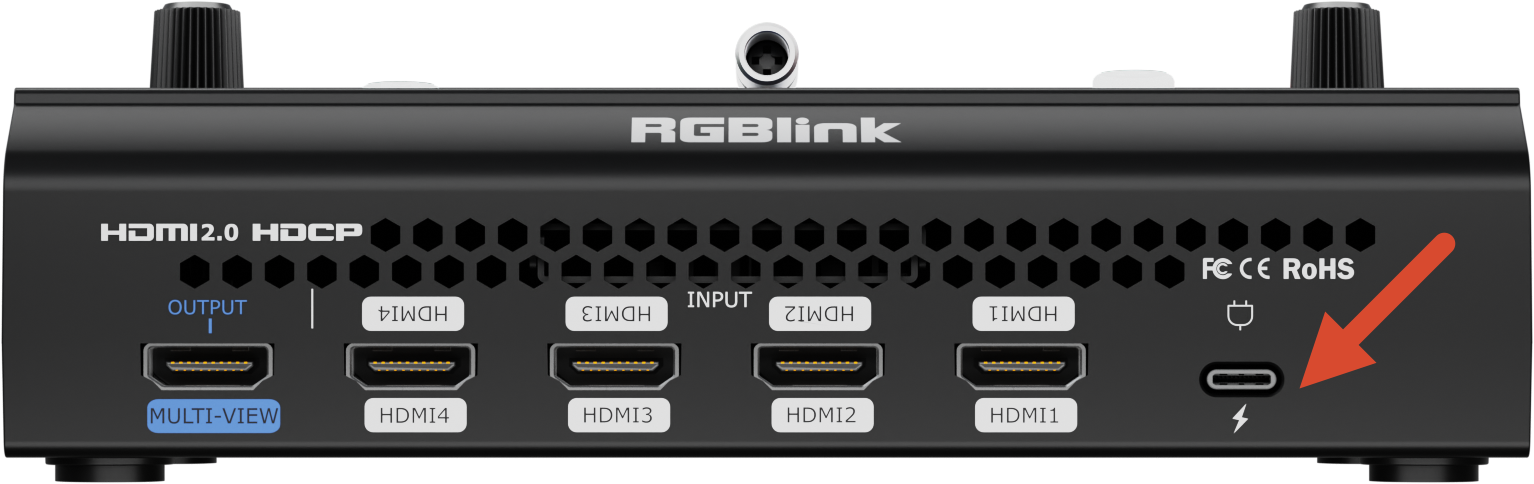
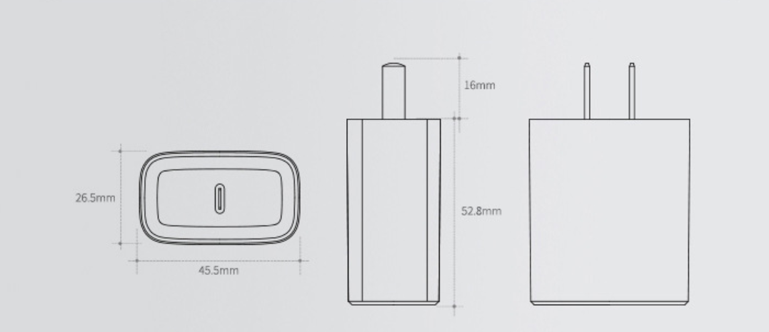
RGBlink mini package includes a PD 12V/2.5A power adapter and power cable.

Before connecting the power supply, make sure the power standard in your country or region is supported.

Firmly connect the power cable to ensure stable power delivery to mini.
๐Ÿ“ข Important

It is recommended to use the power adapter included with mini. If another adapter must be used, make sure it meets the following requirements:

  • Supports the PD3 fast charging protocol
  • Uses a USB-C power port with reversible plug orientation
  • Provides at least 35W of PD output power
  • If the power adapter has two ports, use only the USB-C port for powering mini

The image shows the standard power adapter included with mini series for reference:
Connect Video Sources

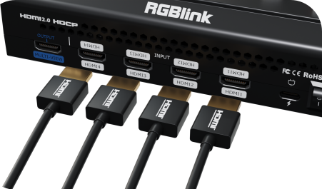
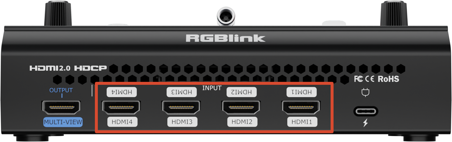
mini provides 4 HDMI input ports and supports input resolutions up to 4K@60Hz.

The device supports automatic deinterlacing. Interlaced signals (i-format) connected through HDMI will be automatically converted to progressive scan.

You can connect any device with an HDMI output, such as a computer or camera, as an input source for mini.

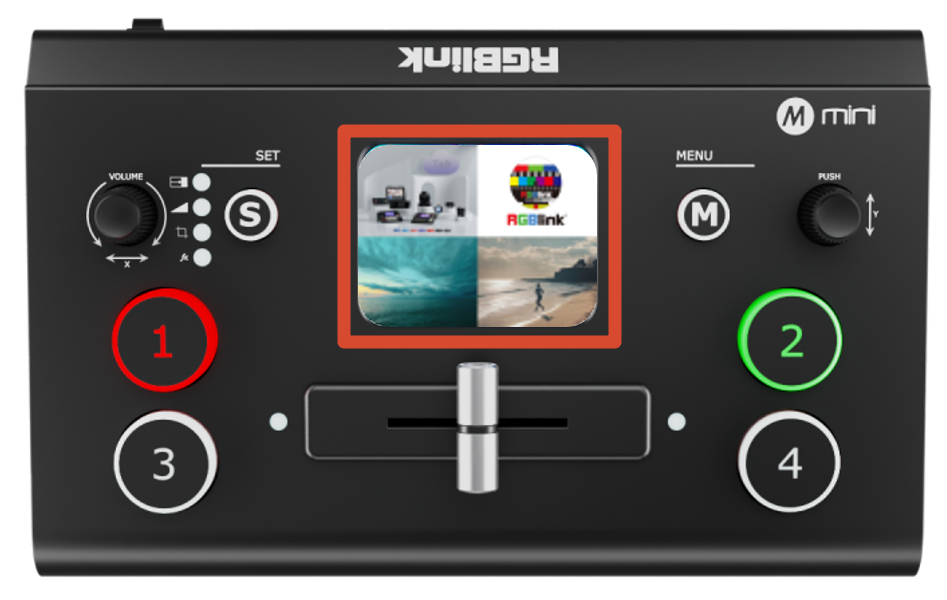
mini features a built-in 2-inch display. After powering on and connecting a video source, the screen will automatically detect the input resolution and display the video feed.
๐Ÿ‘‰
๐Ÿ“ข  Notes
- HDMI cables are not included in mini package and must be purchased separately.
- Some cameras/camcorders use a mini HDMI connector. When connecting these devices, an additional mini HDMI-to-HDMI cable is required.

Connect HDMI Output

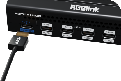
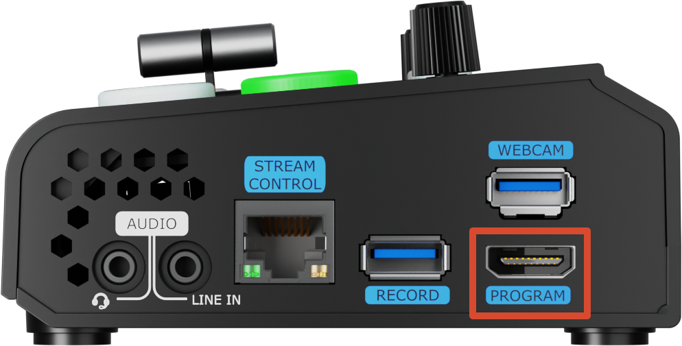
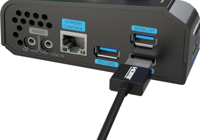
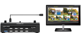
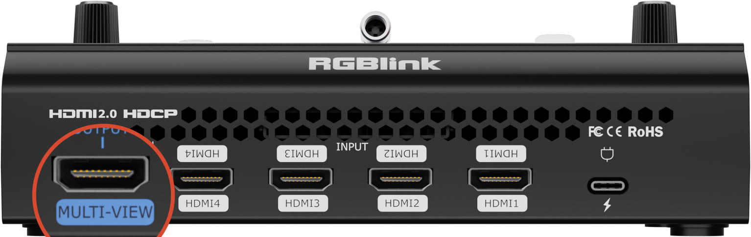
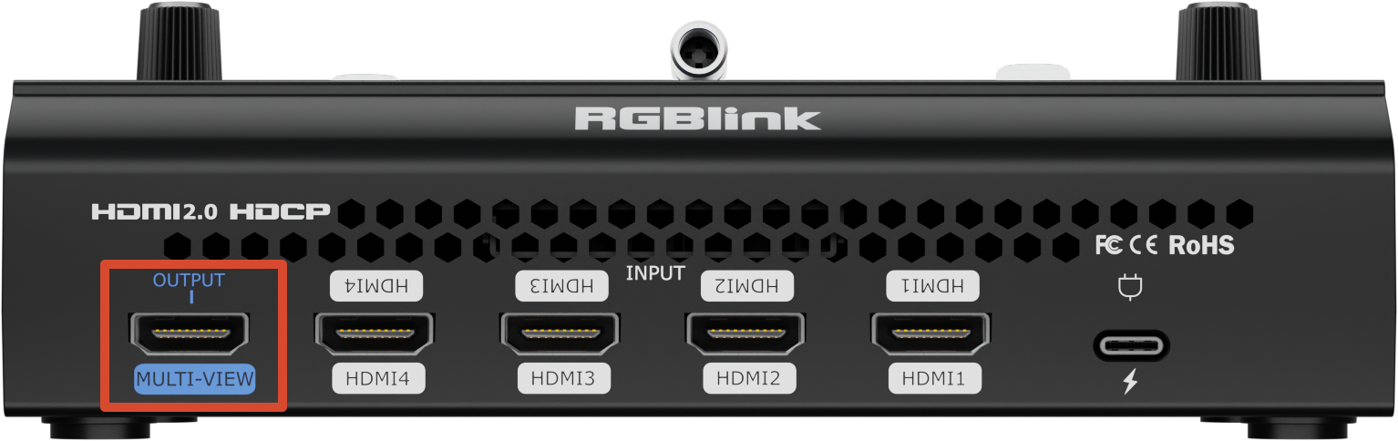
You can use HDMI cables to connect MULTI-VIEW output and PROGRAM output to HDMI monitors for simultaneous preview and program monitoring.
๐Ÿ‘‰
๐Ÿ‘‰

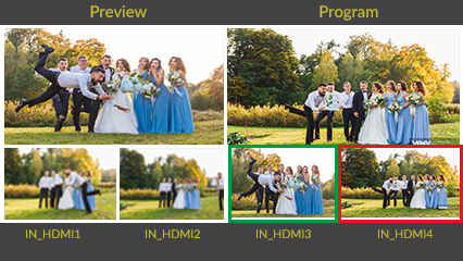
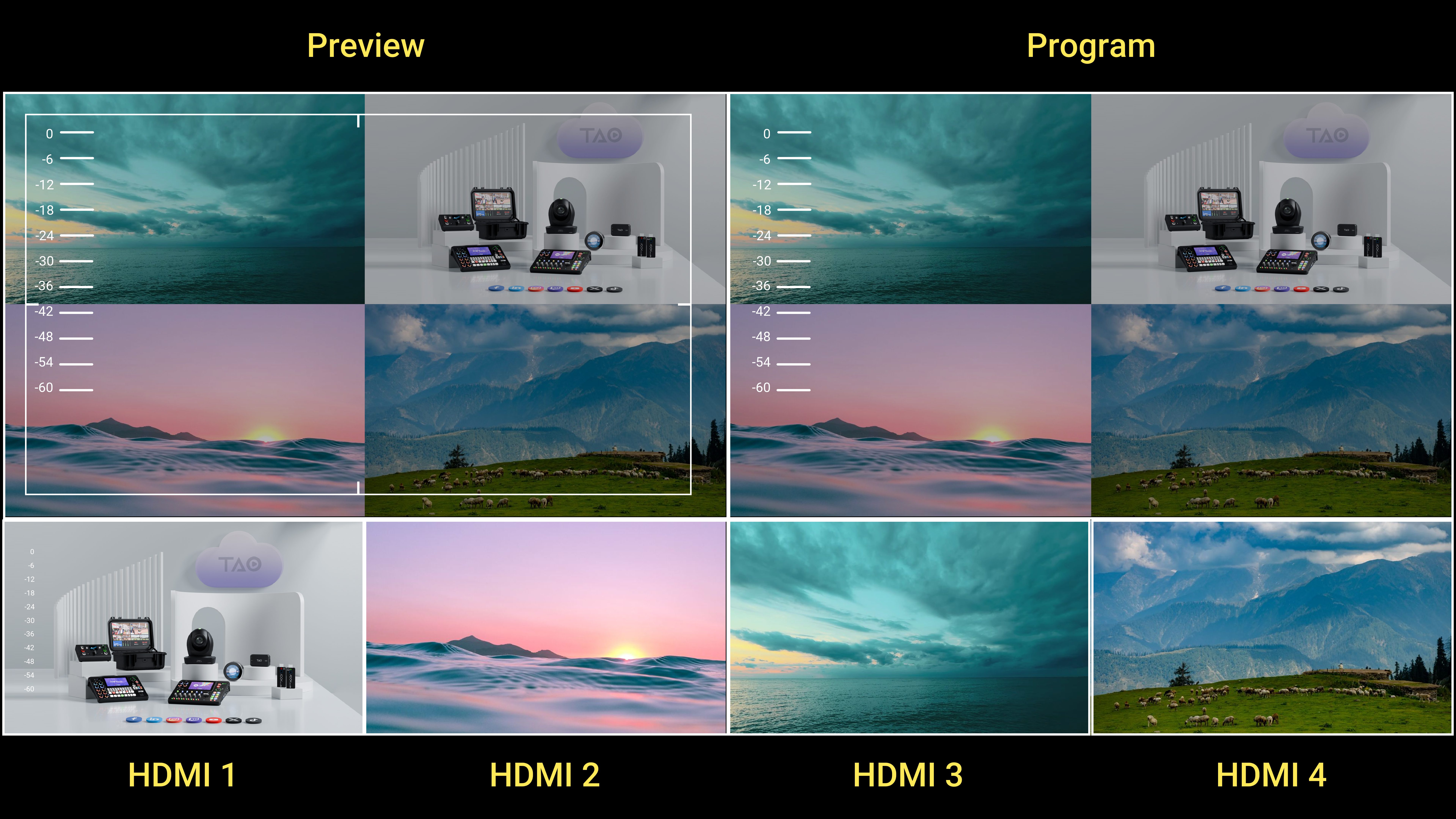
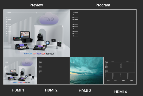
By default, the MULTI-VIEW output displays a multi-view monitoring interface, allowing you to view:

  • Audio and video status of all input sources
  • Current device status
  • Preview (PVW) output
  • Program (PGM) output
๐Ÿ‘‰

In addition to multi-view monitoring, the MULTI-VIEW output can also:

  • Output a fixed input source
  • Output the PGM signal directly

You can switch between PVW, PGM, and input sources in the [Video Output] menu.

mini also supports adjustable HDMI output resolution.

  • Press the [M] button and tap [Video Output] in the menu to select the output resolution format.
  • The HDMI output supports resolutions up to 1080p60.

Connect Microphone and External Monitoring Devices

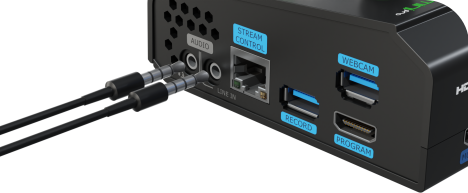
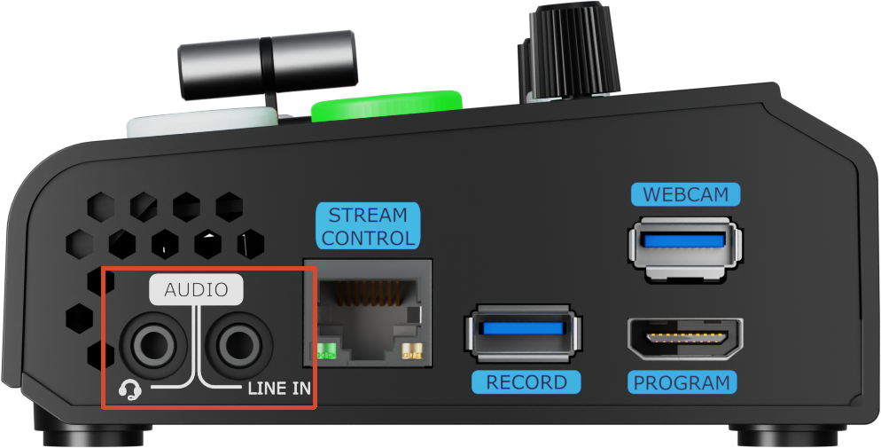
The right-side panel of mini provides two** 3.5mm **audio ports:

  • Audio Output (Line Out)

Connect headphones or speakers for real-time monitoring of the main output audio.

  • Microphone Input (Mic In)

Connect a microphone, wireless mic receiver, or the Line Out output from an external audio mixer for audio mixing.

mini supports:

  • 4-channel embedded HDMI audio
  • 3.5mm analog audio input
  • Multi-source audio mixing

This allows computer audio and microphone audio to be output simultaneously.
๐Ÿ‘‰

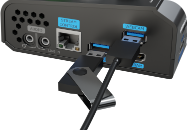
Connect via USB for Recording

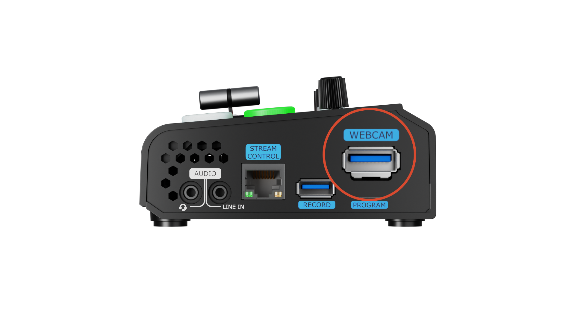
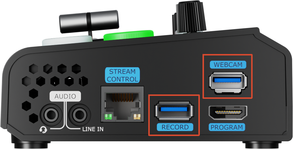
Connect the USB 3.0 port labeled as WEBCAM on mini to your computer using a USB cable. The computer will recognize the device as a USB webcam source.

You can then select mini as a video input source in streaming or recording software such as TikTok, Douyu, Bilibili, or OBS to achieve professional multi-camera production.
๐Ÿ‘‰
**๐Ÿ“ข  Notes**

- If your computer only has USB-C ports, you can use a USB-A to USB-C cable. Make sure the cable supports data transfer.  
- The signal is recognized in Windows and MAC system as "RGBlink USB 3.0 Capture".
- For SSD, check the drive specifications to confirm whether external power is required.  
- Using multiple streaming outputs simultaneously, or using UVC output and recording at the same time, may cause frame drops or lag on mini  .

Connect Router

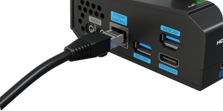
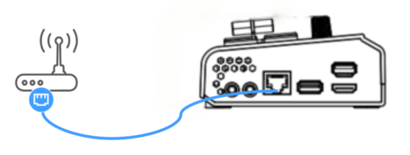
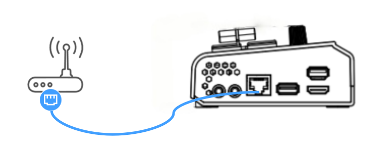
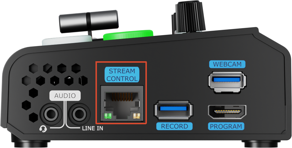
Use a CAT6 Ethernet cable to connect mini to the router.

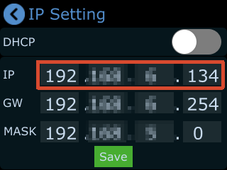
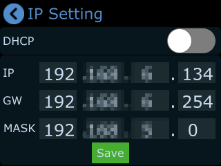
Press the [M] button to enter the menu, then go to: [Menu] > [Settings] > [IP Settings] > [Disable DHCP], manually configure the IP address for mini.

Make sure the router and mini are on the same network segment.
๐Ÿ‘‰

1.2.1Device Control

Touchscreen Operation

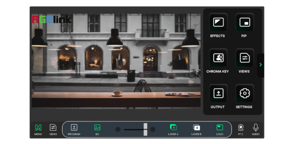
mini features a 2-inch full-color touchscreen, and most device operations are performed through this display.

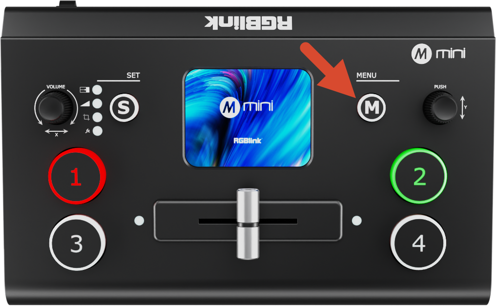
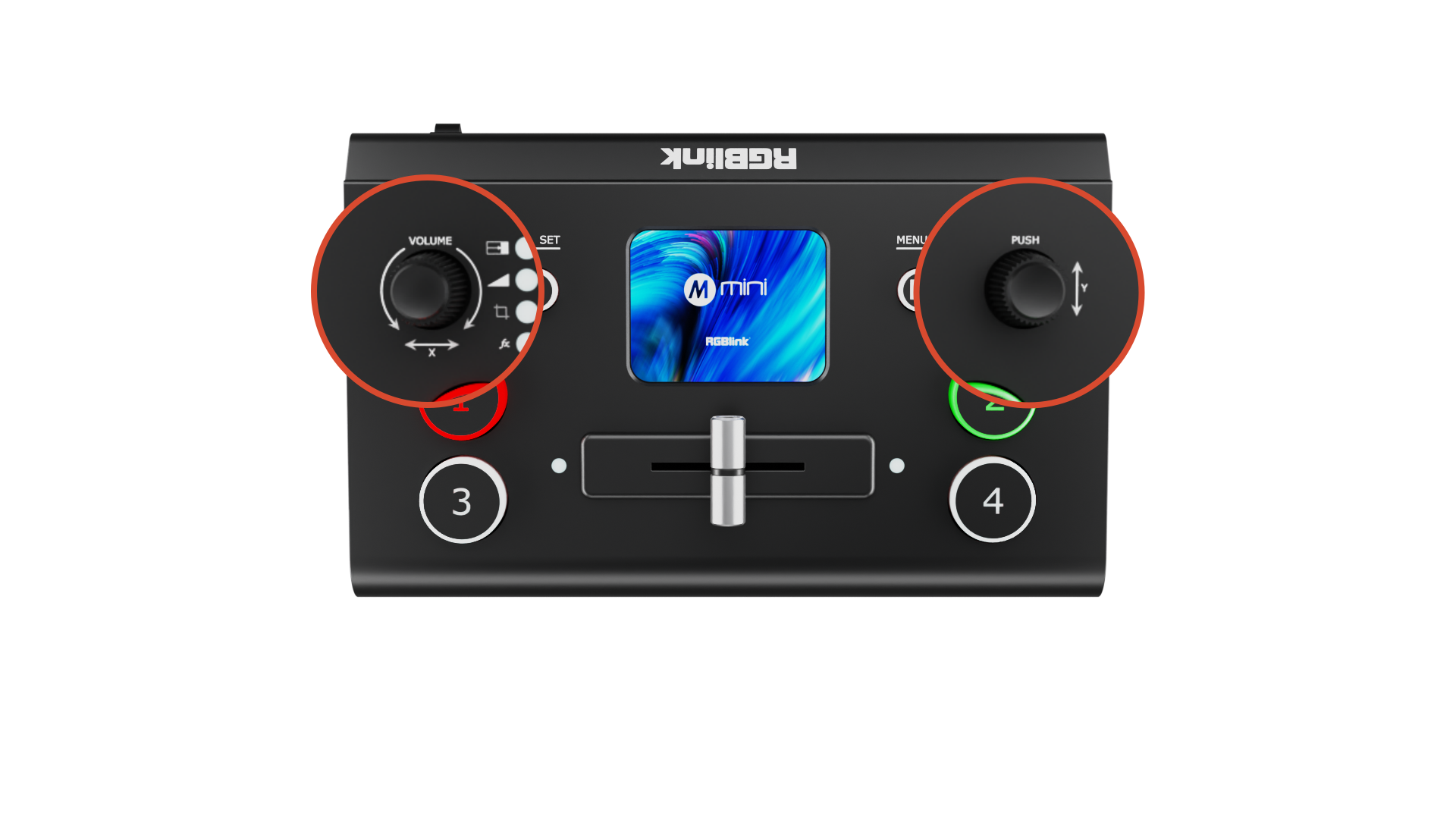
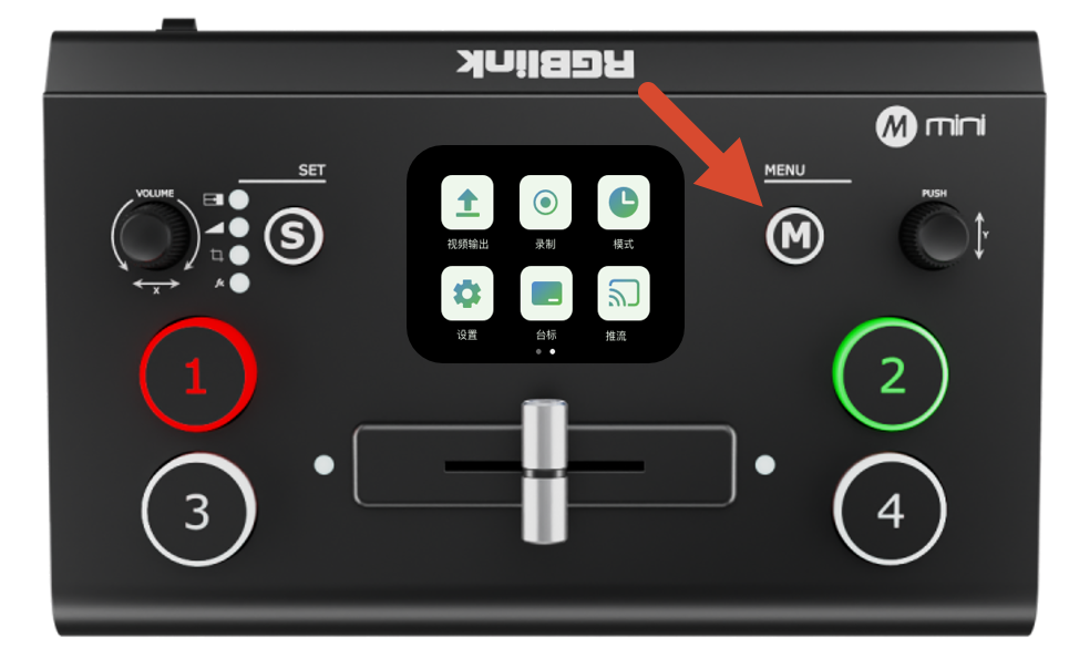
Before using the touchscreen, first familiarize yourself with the [M] button:

The [M] button is the MENU button. Press it once to quickly return to the main menu.

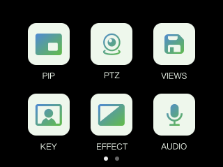
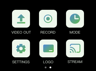
The touchscreen interface of mini is similar to that of modern smartphones. Main menu items are displayed as icons, and you can tap an icon to quickly access the corresponding function page.

Swipe Gestures

mini supports several touchscreen swipe gestures:

  • Swipe left or right to switch between menu pages
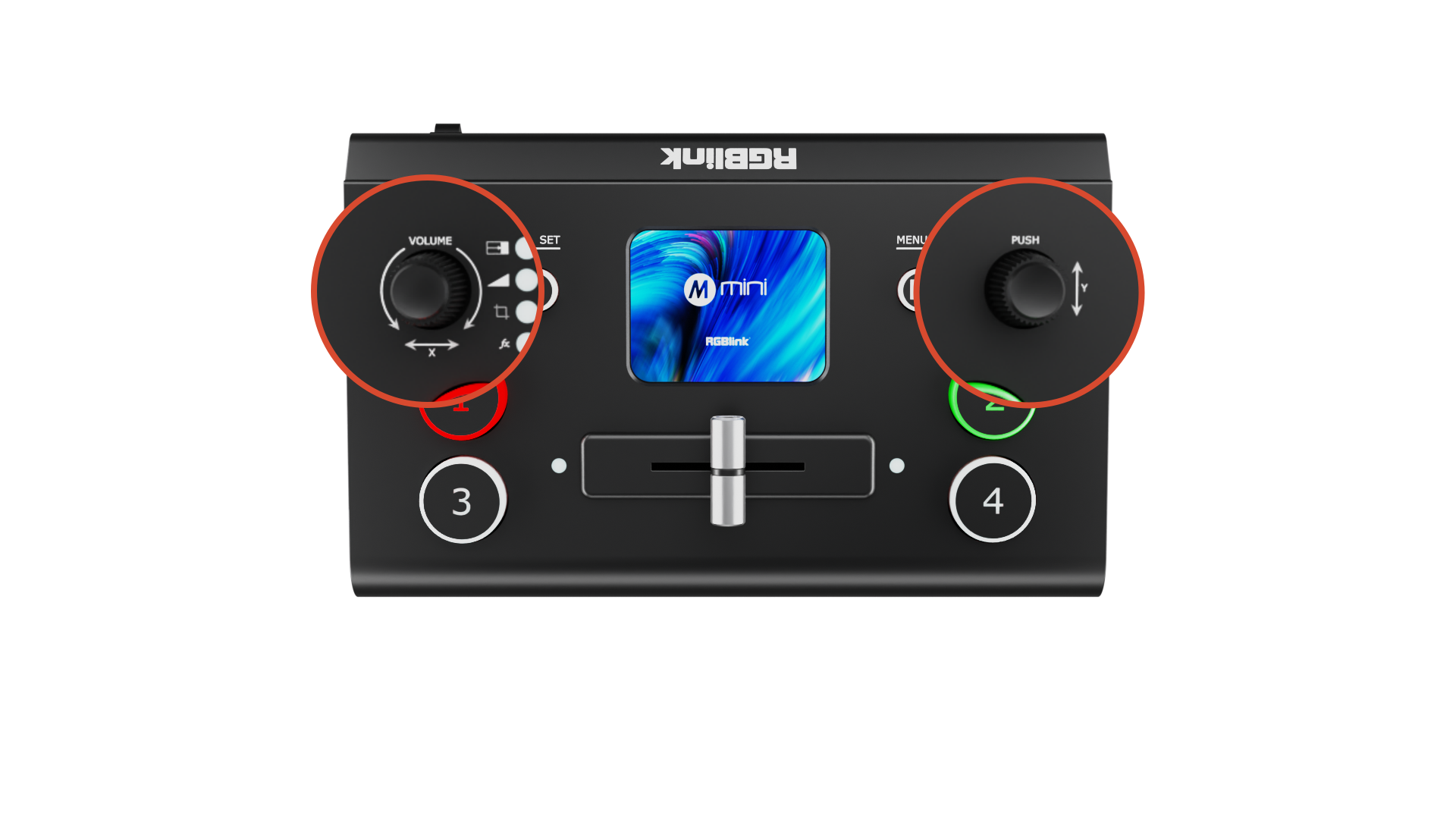
  • In adjustment interfaces such as time settings, you can drag the on-screen slider or use the knobs on both sides of the panel for adjustment

Preset Menu

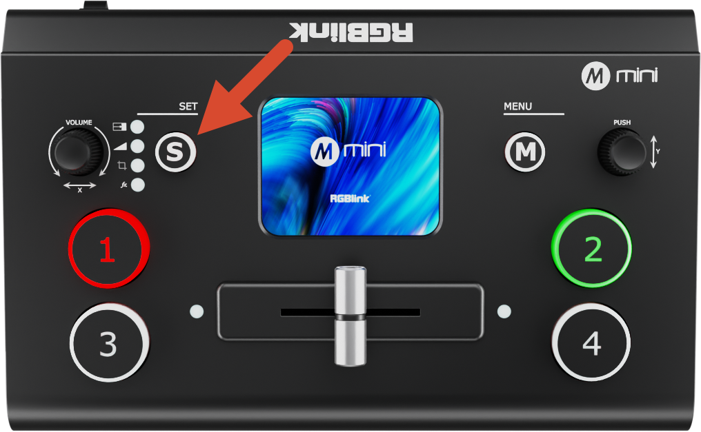
Press the [S] button to enter the preset menu. Press [S] repeatedly to switch between functions.

In this menu, icons on the screen are dimmed by default to indicate inactive status.

The preset recall menu includes:

  • Effects
  • Modes
  • Presets 1โ€“8
  • ...

Web App

You can also remotely control mini through the Web App.

  • Connect mini to the router using an Ethernet cable

  • Go to [Settings] > [IP Setting], enable DHCP, and check the device IP address

  • Enter the device IP address in your browser's address bar to access the web control interface

1.2.2Switch Source

Switch Sources

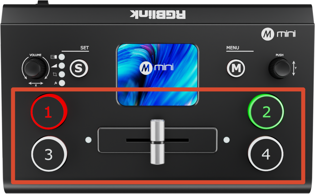
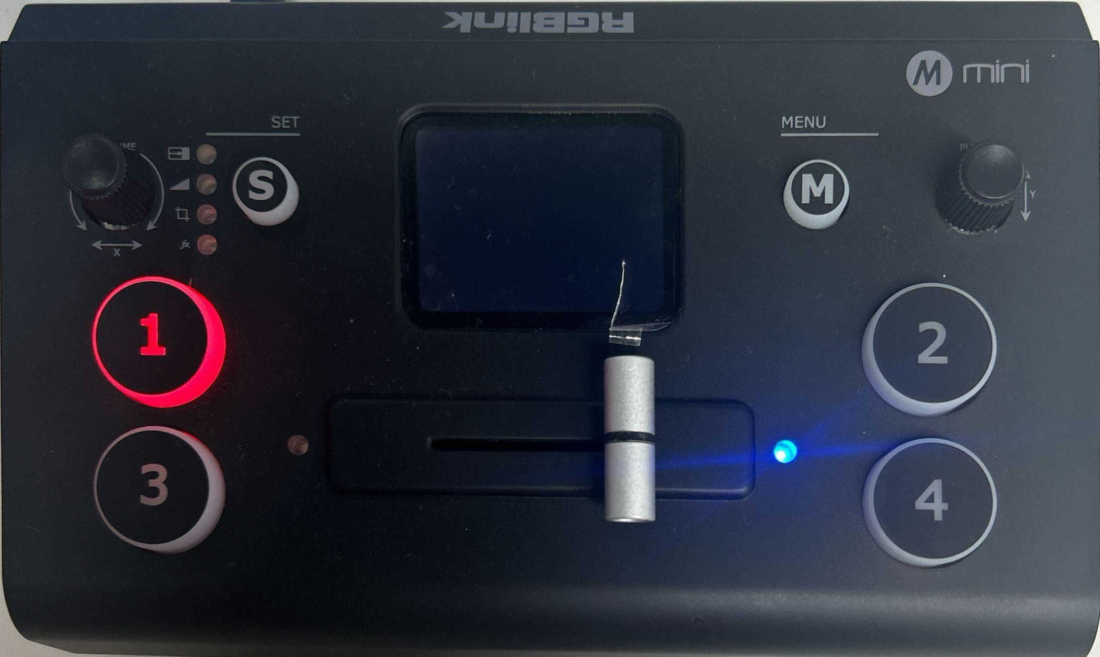
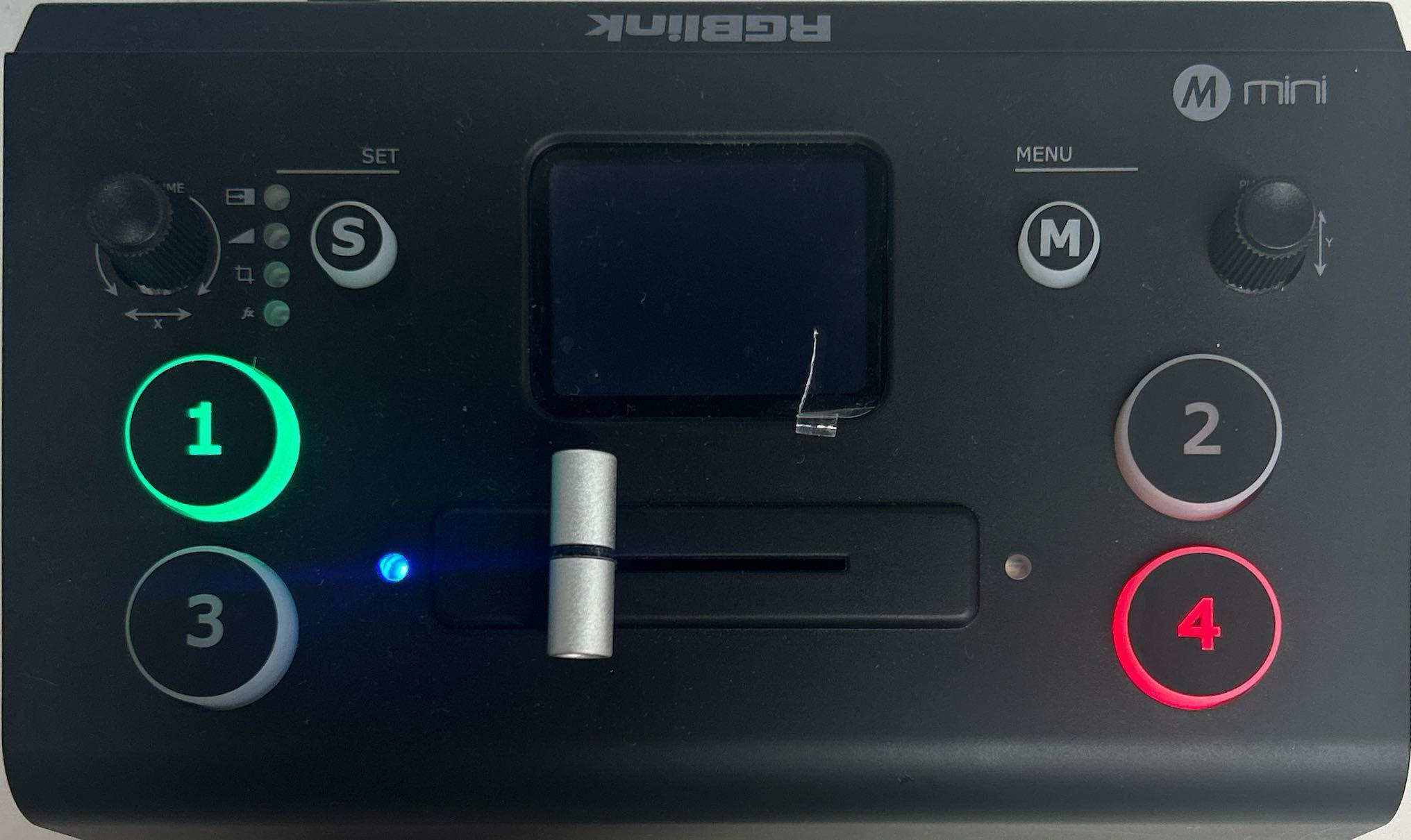
The [1], [2], [3], and [4] buttons on the mini control panel correspond to the four HDMI input ports.

After connecting input sources, the button indicators will display the following statuses:

  • **Solid green: **Signal detected and idle
  • **Flashing green: **The selected source is currently being edited
  • **Solid red: **The source is currently on the main output
  • **Off: **No signal detected, or the input resolution is not supported by mini

When four signal source plug in, the lights on the signal source buttons will appear in four states:

  • **Steady green: **The signal is recognized and no operation is performed;
  • **Flashing green: **The currently selected signal is ready to be switched;
  • **Steady red: **The current signal is in Program output;
  • **Unlit: **No signal source is connected or the resolution of the signal source connected is not accepted.

Transition Effect Settings

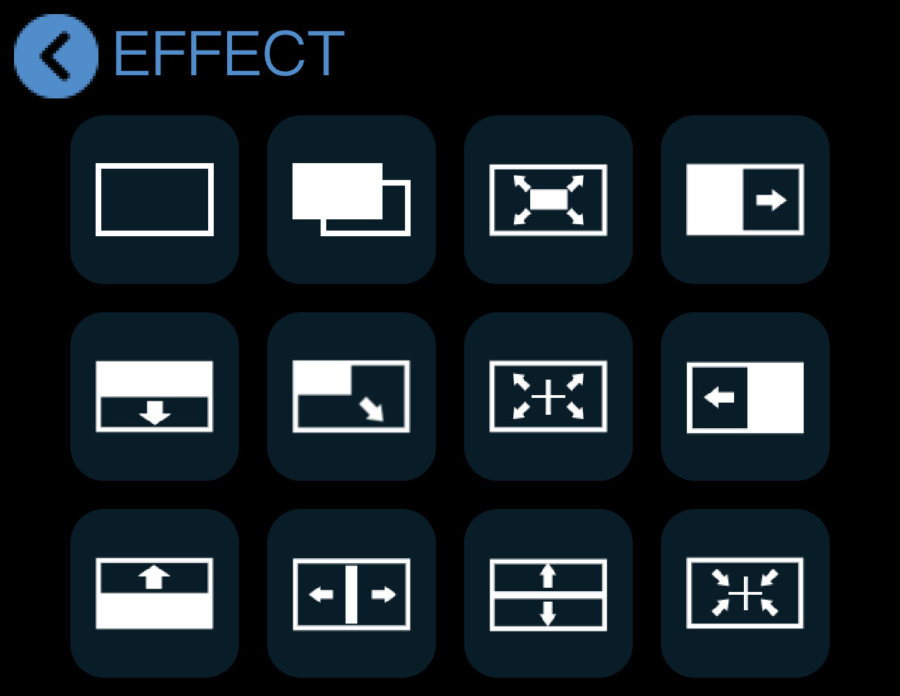
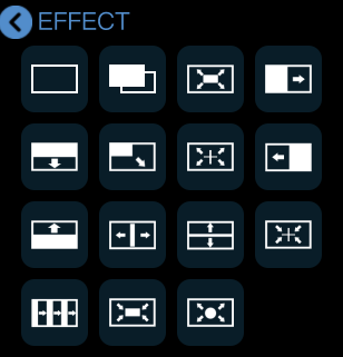
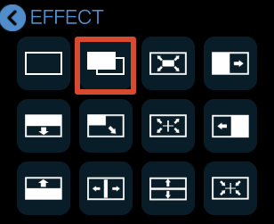
To create more dynamic scene transitions, mini provides 15 transition effects for different production scenarios.

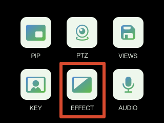
Tap the [EFFECT] icon on the touchscreen to open the transition effect selection menu.

What follows are the 15 transition effects.

Transition Effects
Cut

The Picture 1 switches to Picture 2 instantly with no transition effect.

๐Ÿ‘‰
Mix

During the transition, Picture 1 gradually fades out while Picture 2 gradually fades in, blending together smoothly.

๐Ÿ‘‰
Circle Expand

A circular mask expands outward from the center of the screen to transition from Picture 1 to Picture 2.

๐Ÿ‘‰
Cross Expand

A cross-shaped mask expands outward from the center of the screen to transition from Picture 1 to Picture 2.

๐Ÿ‘‰
Cross Collapse

A cross-shaped mask expands inward from the screen edges toward the center to transition from Picture 1 to Picture 2.

๐Ÿ‘‰
Square Expand

A square mask expands outward from the center to transition between Picture 1 and Picture 2.

๐Ÿ‘‰
Square Collapse

A square mask expands inward from the screen edges, to transition between Picture 1 and Picture 2.

๐Ÿ‘‰
Bottom Up Wipe

Picture 2 wipes upward over Picture 1 until the transition is complete.

๐Ÿ‘‰
Top Down Wipe

Picture 2 wipes downward over Picture 1 until the transition is complete.

๐Ÿ‘‰
Left to Right Wipe

Picture 2 wipes from left to right over Picture 1 until the transition is complete.

๐Ÿ‘‰
Right to Left Wipe

Picture 2 wipes from right to left over Picture 1 until the transition is complete.

๐Ÿ‘‰
Diagonal Wipe

Picture 2 wipes in diagonally over Picture 1 until the transition is complete.

๐Ÿ‘‰
Horizontal Center Expand

Picture 2 expands horizontally from the center toward both sides until it fully replaces Picture 1.

๐Ÿ‘‰
Vertical Center Expand

Picture 2 expands vertically from the center toward both sides until it fully replaces Picture 1.

๐Ÿ‘‰
Venetian Blinds Right

Picture 2 appears in vertical strips expanding horizontally from the center, creating a venetian blinds transition effect.

๐Ÿ‘‰

1.2.3Switch Mode

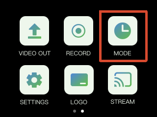
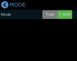
mini provides two switch modes:

  • Fast mode
  • T-BAR mode

T-BAR mode is enabled by default. Tap the corresponding icon to switch modes.

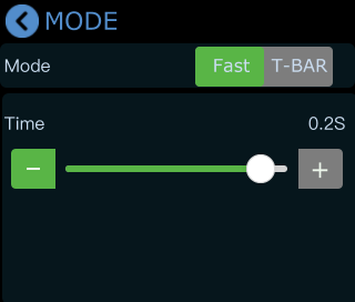
  1. Tap the [Mode] icon on the touchscreen to open the transition mode and transition duration settings menu.

  1. Fast Mode

After selecting [Fast] mode, you can adjust the transition duration using the on-screen slider. The selected value will be displayed in real time.

Once configured, transitions will follow the selected effect and duration time settings.

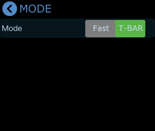
  1. T-BAR mode

For important production scenarios where accurate and stable switching is required, you can use [T-BAR] mode.

In this mode, the next scene can be previewed and edited in the PVW window before going live. After confirming the output, move the T-Bar to switch between PVW and PGM.

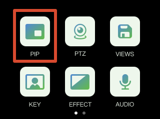
1.2.4PiP (Picture in Picture)

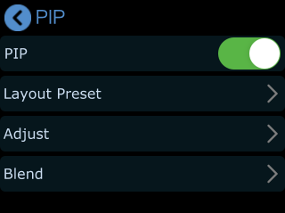
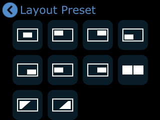
The PiP layout defines the preset scene structure.

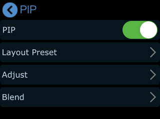
Tap the arrow on the right side of the [Layout Preset] option to open the PiP quick layout selection menu, where you can choose a layout based on your needs.

PiP Layer Settings

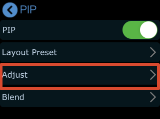
  1. Tap [Adjust] in the PiP menu to enter the layer adjustment interface.

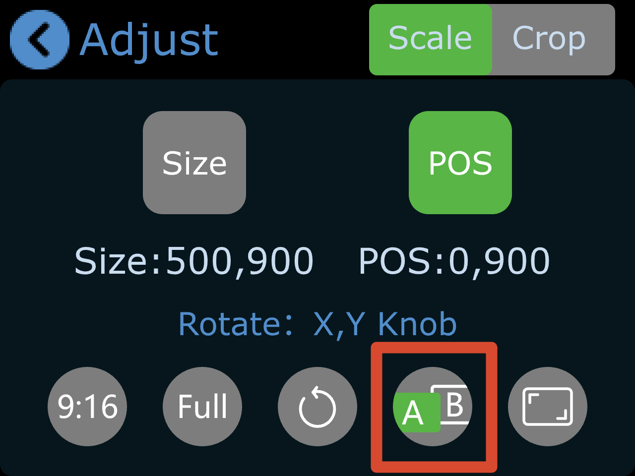
  1. Select Main/Sub Layer
  • Tap [A/B] to select the main or sub layer.
  • Press [1] [2] [3] [4] to select the input source for each layer.

  1. Layer Adjustment

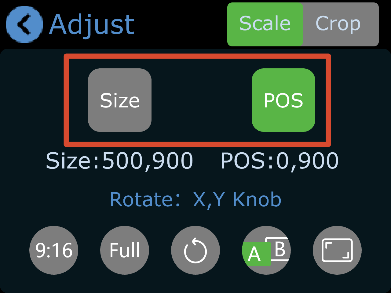
After selecting layer A or B, you will enter the edit mode for that layer.

You can adjust the image using the following methods:

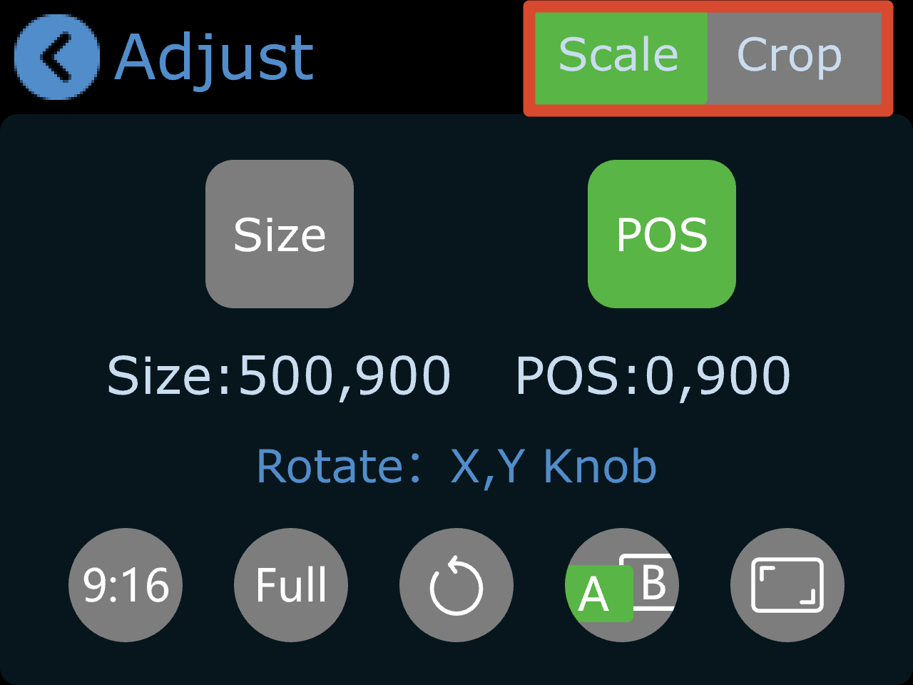
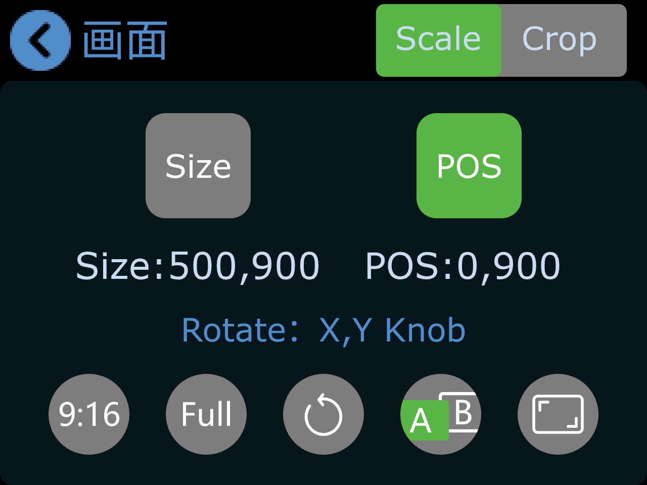
  • Select Size or POS (Position) on the touchscreen, then use the X/Y knobs on the front panel.

  • Use X knob to adjusts width, and Y knob to adjusts height.

  • All changes are saved in real time to the current scene.
  • If aspect ratio lock is enabled, width and height will scale proportionally when adjusted.
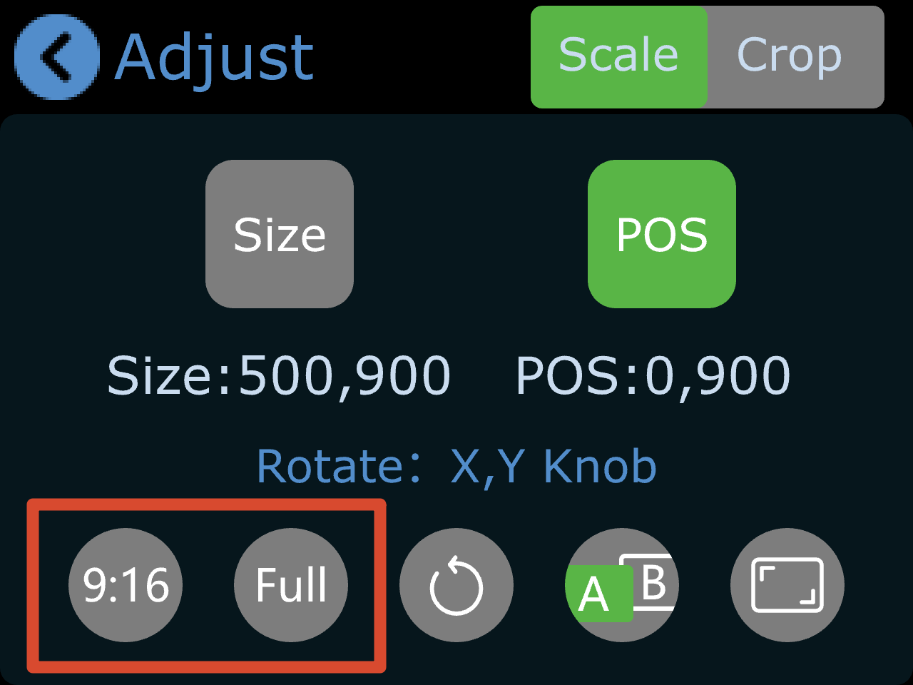
  1. Aspect Ratio Adjustment

The default display mode is full screen.

To support vertical video production, mini supports a 9:16 aspect ratio:

  • Tap [9:16] to switch to vertical mode
  • Tap [Full] to restore full screen

๐Ÿ‘‰
  1. Scale and Crop

Scale and Crop share the same control logic as image adjustment. Refer to the section above.

Blend

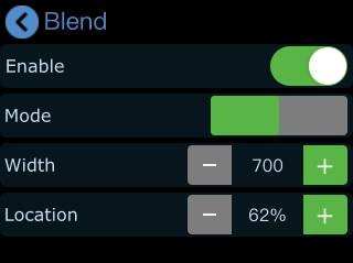
The Blend function creates a soft transition between two input sources by feathering the boundary area for a more natural composite effect.

  1. Go to the PiP menu and select [Blend] to enter the configuration page.

  1. Turn on the Enable switch to activate the blend effect.
  2. Parameters

Blend modes:

  • Left blend
  • Right blend

Adjustable parameters:

  • Width (default: 700)
    • Higher values increase the blur range and soften the edge
    • Lower values create a sharper boundary
  • Position
    • Controls the proportion of the blending area
    • Higher values expand the blend region

Blend settings can be saved to View 1โ€“8 for quick recall.

Following is the illustration of Blend effect.

Display 4 Inputs on PGM

PiP supports up to two input sources in a left-right layout.

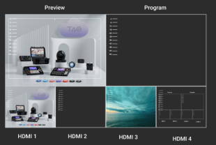
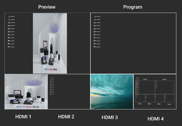
To display all four input sources simultaneously on the main output, combine PiP layout with T-Bar switching:

  • Set both preview and program outputs to PiP layout.
  • Set transition mode to T-Bar and select Fade effect.

  • When the T-Bar is positioned in the middle, both preview and program windows will display all four input sources.

**๐Ÿ“ข  Notes**

Since this display method uses a fade transition effect, the image may appear darker when the T-Bar is centered. You may adjust brightness as needed.

1.2.5Save and Load Views

mini supports real-time view preset saving.

To quickly load your setup the next time the device is powered on, save the current configuration as a view preset.

View presets store all current parameters, including:

  • Picture-in-picture settings
  • Chroma key settings
  • Input source assignments
  • PTZ scene settings
  • Other current configuration parameters

Once saved, views can be recalled instantly using the [S] button.

  1. Save a View Preset

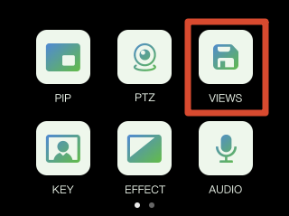
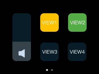
After completing your setup, press the [M] button and open the [VIEWS] menu.

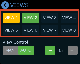
Tap a VIEW icon to save the current configuration to VIEW 1โ€“8.

  1. Status Indicators
  • Yellow Icon: view that being used
  • Green Icon: saved views
  • Grey Icon: blank view
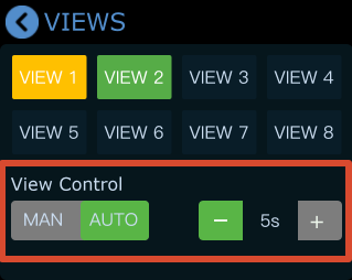
  1. View Control
  • [MAN]: Manual switching
  • [AUTO]: Automatic switching
  • Scene transition interval settings

  1. Load a View Preset

Press the [S] button to open the recall interface. From this menu, you can quickly access VIEW 1โ€“8.

  1. Modify a Loaded View Preset

After recalling a scene, you can still adjust the layout if needed:

  • Tap [PiP] on the touchscreen.
  • Select the main or sub layer.
  • Use the [1][2][3][4] buttons to switch inputs.
  • Use the X/Y knobs to adjust image size and position.

All changes are saved to the current working state in real time.

  1. Re-save a View Preset

To make updated settings available for future load, the view must be saved again.

  • You can:
    Overwrite the current scene.
    Or save the configuration as a new scene.

Repeat the save steps above to complete the update.

1.2.6Audio

mini features a built-in audio control system for convenient adjustment of all input audio sources.

Supported features include multi-channel audio mixing and AFV (Audio Follow Video) mode. This makes mini suitable for live streaming, recording, and multi-source audio production.

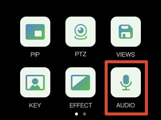
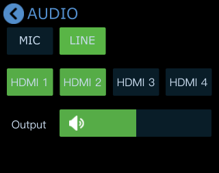
Press the [M] button to return to the main menu, then tap [Audio] to enter the audio settings page.

Adjust Volume

In the [AUDIO] settings interface:

  • Drag the on-screen slider to adjust the main output volume
  • Or use the front-panel knobs for adjustment
    • Y knob: MIC, LINE, and HDMI 1โ€“4 embedded audio
    • X knob: the main output

Tap MIC, LINE or HDMI 1โ€“4 to open detailed settings for each input source.

MIC and LINE

mini provides:

  • MIC: 1 microphone input
  • LINE: 1 Line-in input

This means mini can be connected to microphones or line-level audio devices.

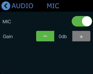
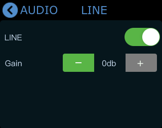
Tap [MIC] or [LINE] to open detailed settings.

  • Enable/disable input

    • Gray: Disabled
    • Green: Enabled
  • Adjust input volume

    • Tap [-] or [+] to adjust volume.
    • Adjustment range: 0โ€“100
    • Gain/Step size: 10 db

MIX

mini supports multi-channel audio mixing. Up to 6 audio sources can be mixed simultaneously:

  • 4 HDMI embedded audio channels
  • 1 MIC input
  • 1 LINE input

MIC and LINE can also be enabled simultaneously.

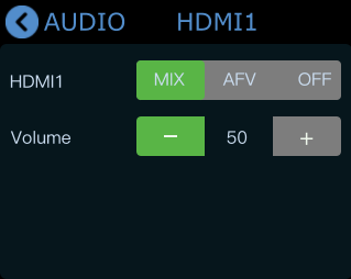
In the [Audio] menu:

  • HDMI 1โ€“4 represent the four HDMI audio inputs
  • Tap HDMI 1โ€“4 for detailed settings

Tap [Mix] to enable MIX mode and mix HDMI audio into the main output.

You can independently adjust the volume level of HDMI 1โ€“4 audio channels.

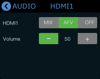
AFV (Audio Follow Video)

mini also supports AFV (Audio Follow Video) mode.

Tap [AFV] to enable the mode. Audio transitions automatically follow video switching for smoother synchronization.

How AFV works:

  • When an HDMI audio channel is set to AFV mode, its audio will only be output when that HDMI channel is switched to the PGM output.
  • All four HDMI channels on mini support independent AFV configuration. For example: If HDMI 1 is set to AFV mode, its embedded audio will automatically become active when HDMI 1 is switched to the PGM output.

4FAQ

Need help?

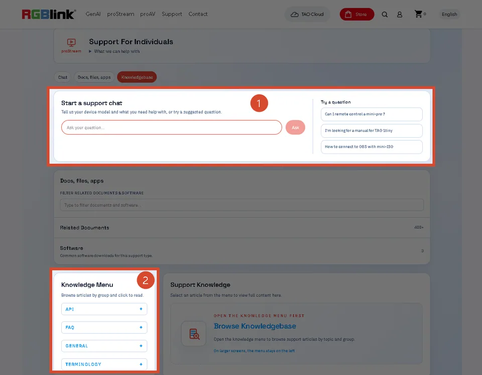
Choose one of the following support options:

  • AI Support Search (Recommended): Visit Support > Support For Individual on the RGBlink official website and ask the RGBlink AI Bot for quick answers to your questions.
  • FAQs: Visit Support > Support For Individual on the RGBlink official website and browse Knowledge Menu > FAQ for relevant information.
  • Contact Technical Support: Visit this manual, Technical Support page for our contact details.

Document image

1.2.7Video Output

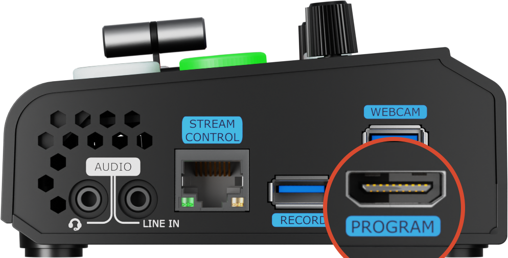
mini provides two independent video outputs:

  • PROGRAM (PGM) output
  • MULTI-VIEW (PVW) output

mini-Right Panel mini Rear Panel

This allows simultaneous program output and multi-view monitoring without manual switching, making operation more intuitive and efficient.

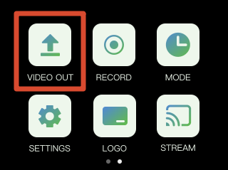
Press the [M] button to open the main menu, then tap [VIDEO OUT] to enter the output settings page.

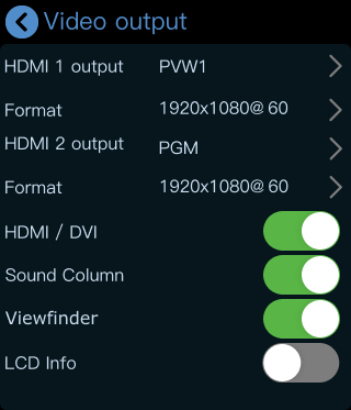
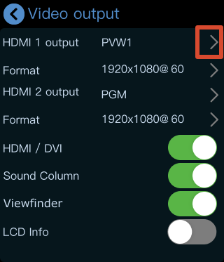
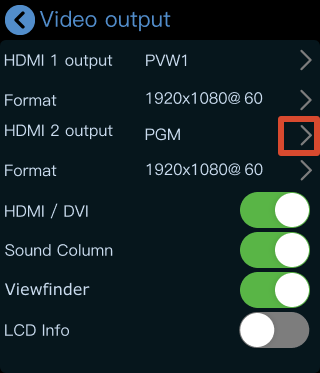
HDMI 1 Output

HDMI 1 outputs the multi-view preview (PVW) screen by default.

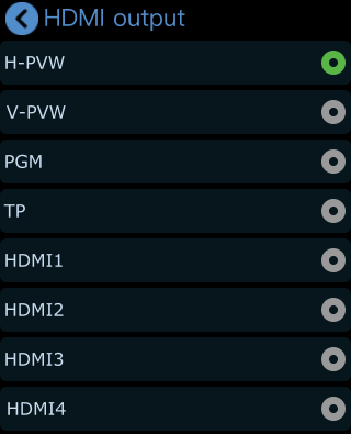
Depending on your workflow, it can also be configured to output:

  • PVW 1/2
  • PGM
  • HDMI 1โ€“4
  • TP: Test Pattern

Go to the [VIDEO OUT] menu to configure [HDMI 1 output].

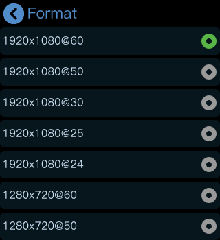
  1. Output Resolution
  • ** **Tap [Format] to configure HDMI output resolution according to your requirements.

  • Tap the [>] icon on the right side to select another output source and configure the output resolution.

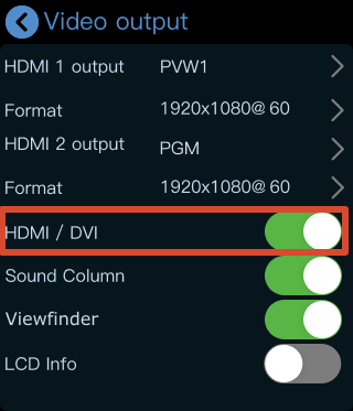
  1. HDMI/DVI Mode

The [HDMI/DVI] option is enabled by default. This feature is designed for setups using different types of display devices simultaneously, such as:

  • DVI devices
    • LED controller/sender cards
    • Monitors with DVI input
  • HDMI devices
    • Monitors with HDMI input

When enabled, mini automatically adapts to the connected display type.

  1. View the Output

After connecting a display, you can directly monitor the configured output. After configuration:

  • Press the [M] button to return to the main menu
  • Press [M] again to switch pages
  • Press [M] once more

The touchscreen will then enter the 4-view monitoring interface.

๐Ÿ‘‰
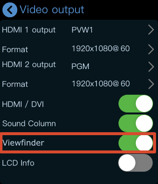
  1. Viewfinder

When [Viewfinder] is enabled, a white frame will appear on the PVW preview screen to assist with composition and framing.

  1. LCD Information Display

When [LCD Info] is enabled, the interface switches from Simple Mode to Standard Mode.

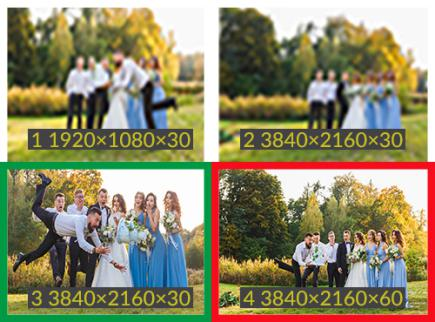
In Standard Mode, the resolution of all four input sources is displayed.

Simple๐Ÿ‘‰Standard

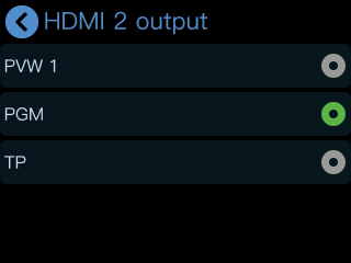
HDMI2 Output

HDMI 2 outputs the PGM feed by default.

Depending on your workflow, it can also be configured to output:

  • PVW 1/2
  • HDMI 1โ€“4
  • TP: Test Pattern
  1. Go to the [VIDEO OUT] menu to configure [HDMI 2 output].

  1. Tap the [>] icon on the right side to select another output source and configure the output resolution.

1.2.8LOGO

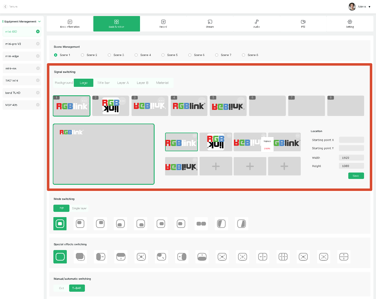
Import Logo Material in TAO Cloud

Open TAO Cloud and go to [My Collection] > [My Devices], then open the management page for the target mini device.

Under [Basic Settings], select the target scene and upload or add logo material in the content management section.

Adjust the Logo Position

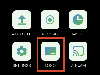
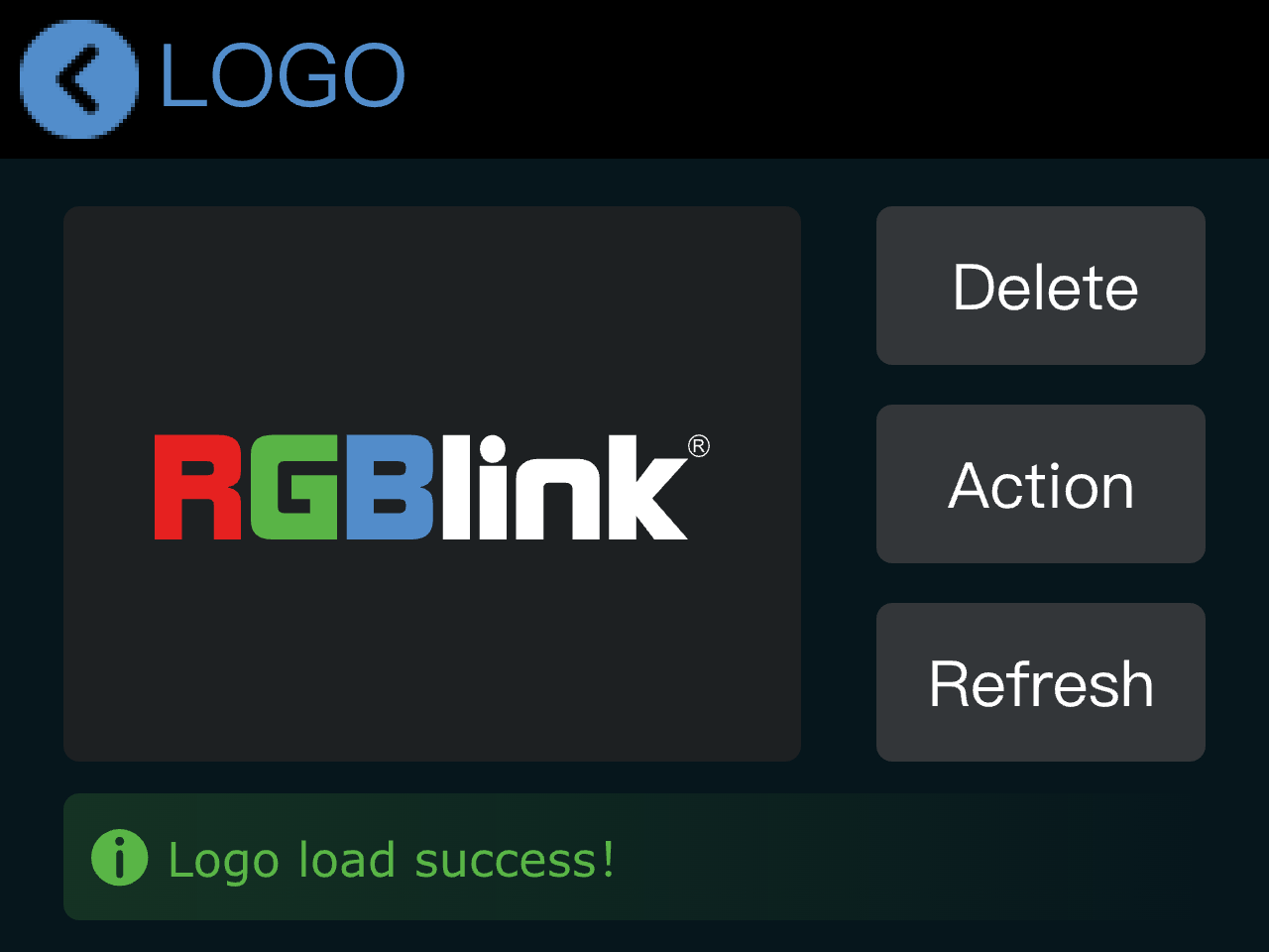
Open the [Logo] menu from the main menu on mini.

The logo settings page will display the material uploaded in TAO Cloud.

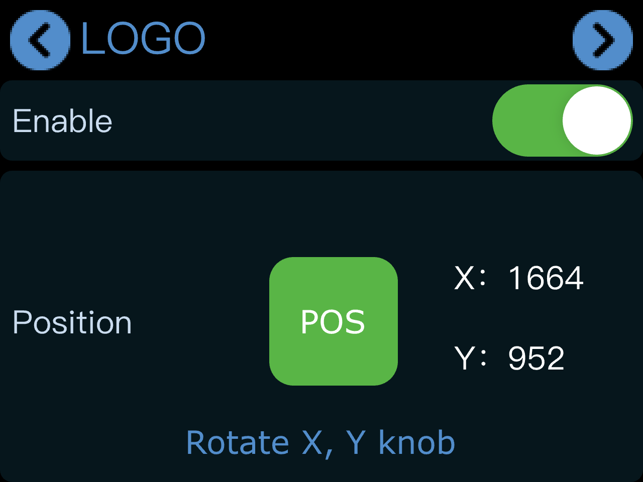
Tap [Action]. After enabling the logo function, the logo will appear in the current preview screen.

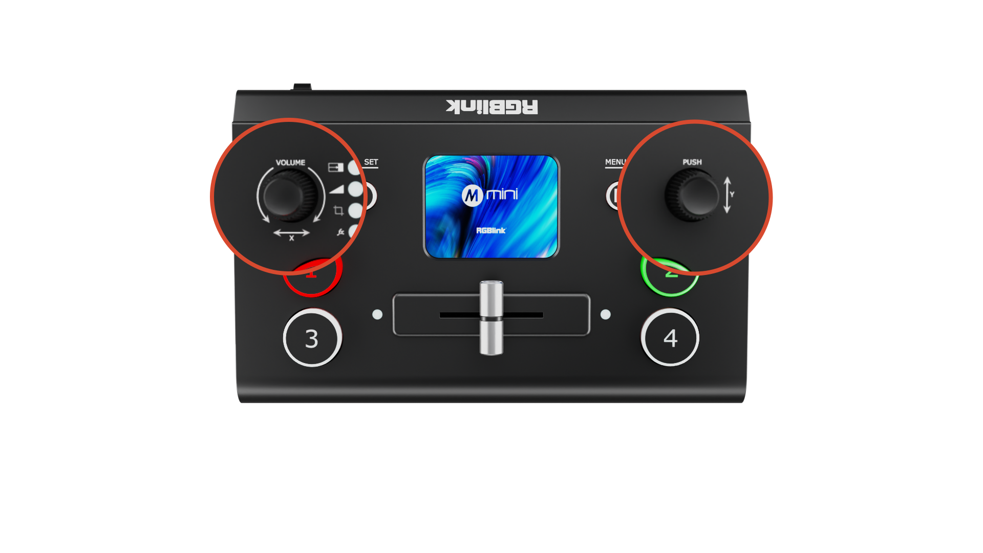
Use the knobs to adjust the position:

  • X knob: adjusts horizontal position
  • Y knob: adjusts vertical position

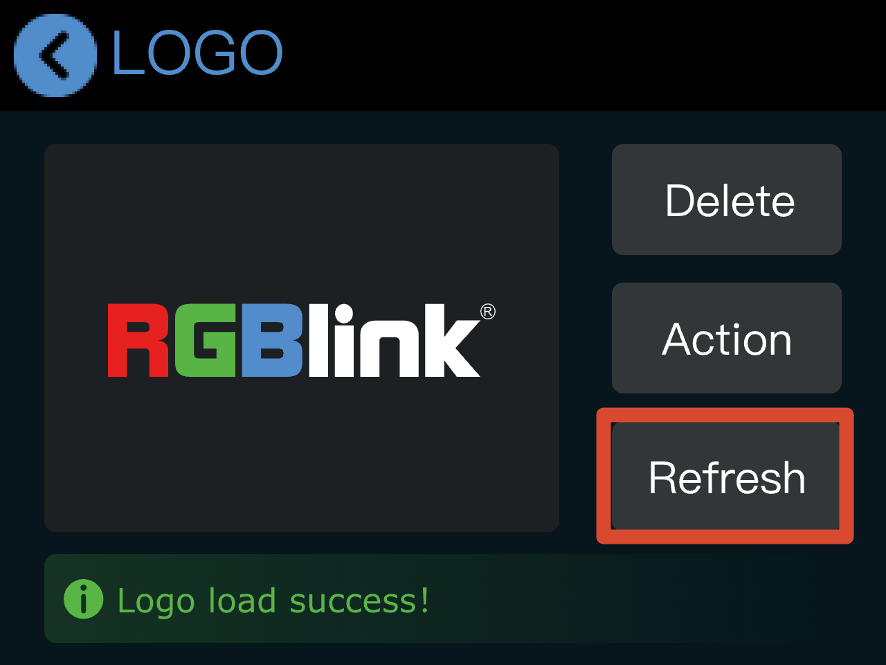
Logo refreshment must be performed in TAO Cloud.

Go to the mini device management page and select a new logo asset under [Basic Settings].

Then return to the logo settings page on mini and tap [Refresh] to update the current logo.

1.2.9Settings

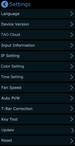
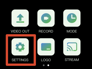
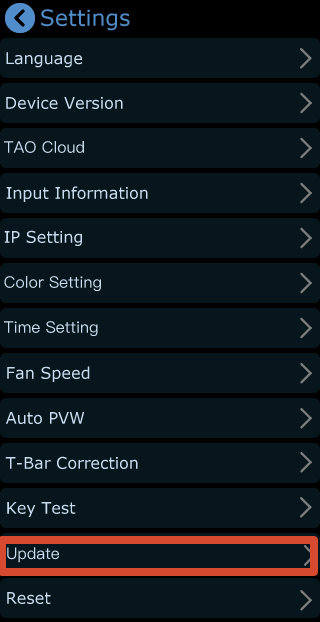
Tap [Settings] to open the system settings menu.

The settings menu includes:

Language, Device Version, Input Information, IP Setting, Color Setting, Time Setting, Fan Speed, Auto PVW, Reset, T-Bar Correction, Key Test, Update and Reset.

Language

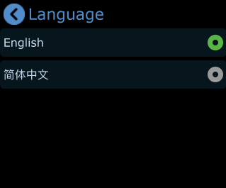
Go to [Settings] > [Language] to open the language settings page.

mini supports:
โ— ็ฎ€ไฝ“ไธญๆ–‡
โ— English

Select the preferred interface language as needed.

Device Version

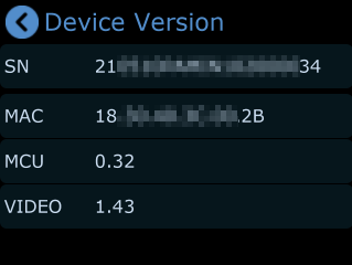
Go to [Settings] > [Device Version] to view device information.

Available information includes:

  • SN: Device Serial Number
  • MAC address
  • MCU version
  • Video version

Input Information

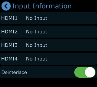
Go to [Settings] > [Input Information] to view HDMI input status.

In this page:

  • If no HDMI input is detected, the screen displays [No Input]
  • If an HDMI source is connected, the input resolution will be displayed
  • If the input signal is interlaced, [Deinterlace] can also be enabled.

Color Setting

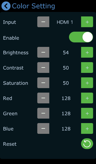
Go to [Settings] > [Color Management] to open the image adjustment page, you can independently adjust HDMI 1โ€“4 input sources.

After enabling Color Management, you can use the following controls:

  • Tap [-] or [+] to switch HDMI input sources, or use the front-panel X knob to select inputs
  • Tap [-] or [+] to adjust image parameters, or use the front-panel Y knob for adjustment
    • Brightness
    • Contrast
    • Saturation
    • Other image parameters

This helps achieve more consistent and balanced output across different sources.

If incorrect settings are applied, tap [Reset] icon to restore default parameters.

Fan Speed

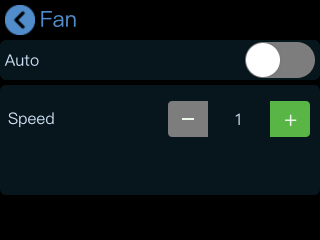
Go to [Settings] > [Fan] to configure fan settings.

โ— When Auto mode is enabled, mini adjusts fan speed automatically
โ— When Auto mode is disabled, fan speed can be adjusted manually

Four fan speed levels are available.

Auto PVW

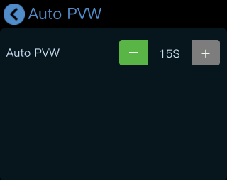
Go to [Settings] > [Auto PVW] to configure automatic preview return timing.

The system can automatically return to the default PVW after a period of inactivity.

  • Default value: 15 seconds
  • Adjustment step: 15 seconds

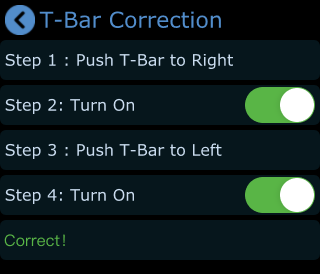
T-Bar Correction

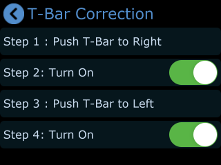
Go to [Settings] > [T-Bar Correction] to open the calibration page.

Follow these steps to complete:

  1. Move the T-Bar fully to the right

  1. Enable the switch
  2. Move the T-Bar fully to the left

  1. Enable the switch again
  2. When calibration is complete, the screen will display "Correct!"

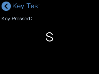
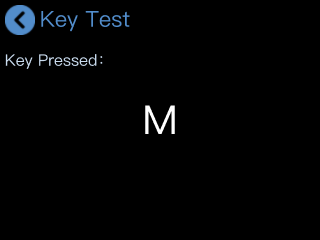
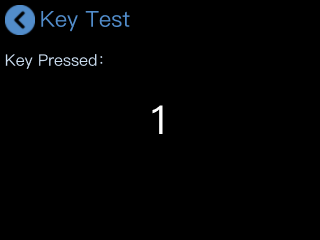
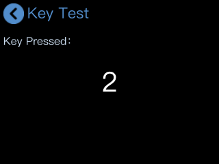
Key Test

Tap [Key Test] to enter the test interface.

Press the [M] button or other buttons and verify that the displayed information matches the button being pressed to confirm proper operation.

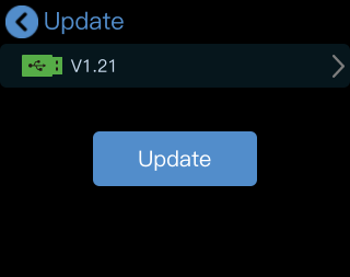
Update

Tap [Upgrade] to enter the system upgrade interface.

Tap [Upgrade] to start upgrading mini.

๐Ÿ“ข ** Important**

Make sure the network connection is stable before and during the upgrade process.

![](https://rgblinkw3media9490.blob.core.windows.net/product-images/online-document-images/mini-v3/yuque-1779181161351-5a228267.png)

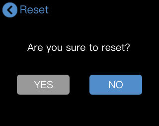
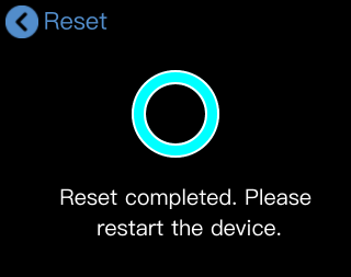
Reset

Tap [Reset] to enter the factory reset interface.

Tap [YES] to restore the device to its default settings.

After the reset is complete, reboot the device.

2.1TAO Cloud Feature Licensing

mini v3 is the industry's first video switcher with customizable feature licensing.

Users can activate features through TAO Cloud using:

  • Monthly Plan
  • Separate Lifetime Plan: for individual features
  • Pay Once, Use Forever

This provides flexible access based on different production needs.

Function TypeAuthorization MethodFunction Details
Basic FunctionsFree+ Picture-in-Picture + View + Transition Effects + Switching Modes + Audio + Logo + PGM HDMI Output + WEBCAM Capture Output
TAO Cloud Licensed FunctionsMonthly/Lifetime Subscription PlanProduction + Recording + PTZ Control + Chroma Key Network Streaming + Stream + MP4 Playback (coming soon)
+ TAO Remote Control + NDI Encoding/Decoding (coming soon) + UVC Camera (coming soon) + Overlays (coming soon) + Background (coming soon) + MIC IN (coming soon)
One-Time Lifetime UnlockUnlock lifetime access to all features

2.1.1Activate TAO Cloud Benefits

Bind mini to TAO Cloud

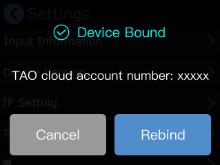
Tap [Settings] > [TAO Cloud] to open the binding page.

You can bind RGBlink devices such as mini to TAO Cloud for management and efficient content production.

Connect mini to the Network

If mini is not bound to TAO Cloud and has no network connection, a network warning message will appear.

Connect mini to a router using an Ethernet cable.

For detailed network setup instructions, refer to 2.1.3Direct Ethernet Connection

IP Settings

Go to [Settings] > [IP Settings] to configure the network.

  1. When DHCP is enabled, mini automatically obtains an IP address from the router
  2. When DHCP is disabled, you can manually configure
  • IP address
  • GW: Gateway
  • MASK: Subnet mask

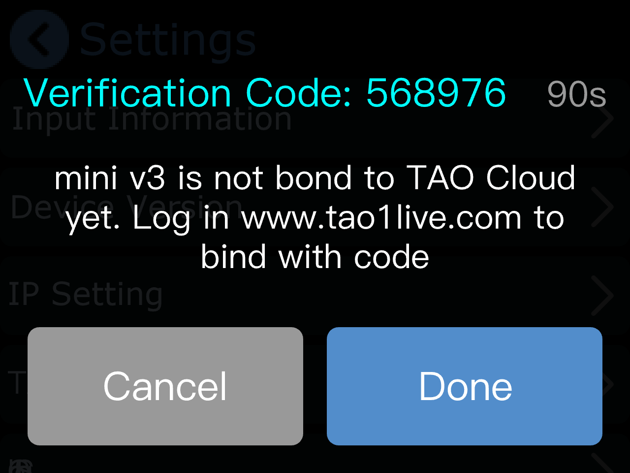
Get the Verification Code

After the network connection is established:

Tap [Settings] > [TAO Cloud]

The device binding verification code will be displayed on the screen.

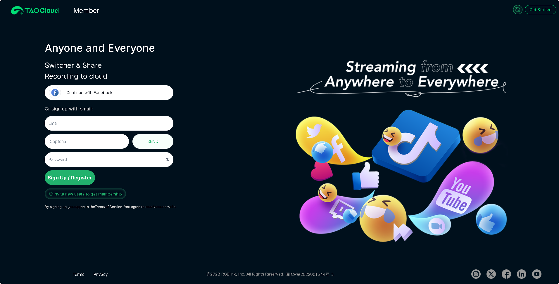
Log In to TAO Cloud

Open the official TAO Cloud website: TAO Cloud

Continue with Facebook account or sign up with e-mail.

Then tap [Send] for verification code.

After receiving the verification code, enter it and log in.

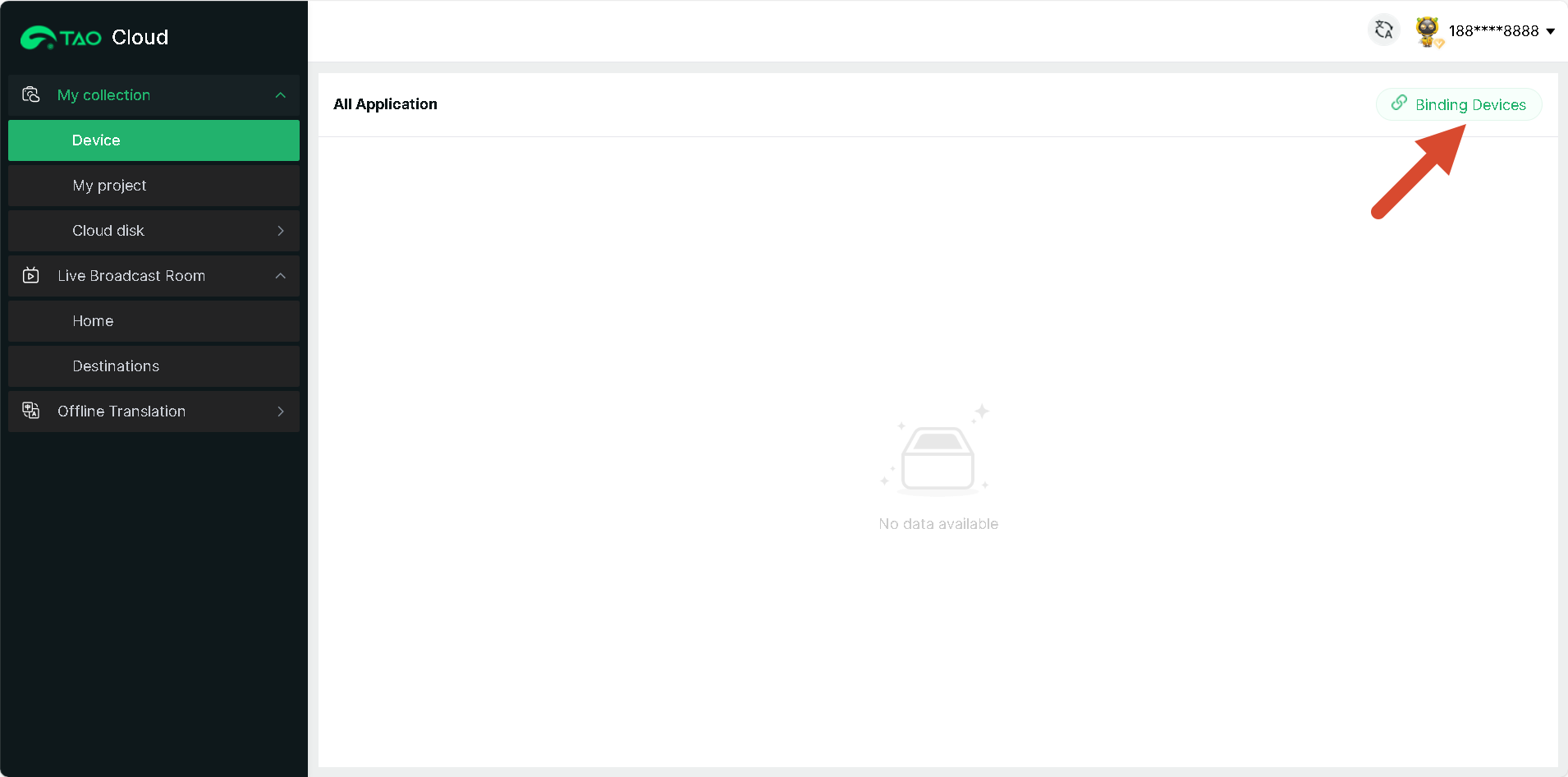
Bind the Device

After logging in to TAO Cloud, go to:

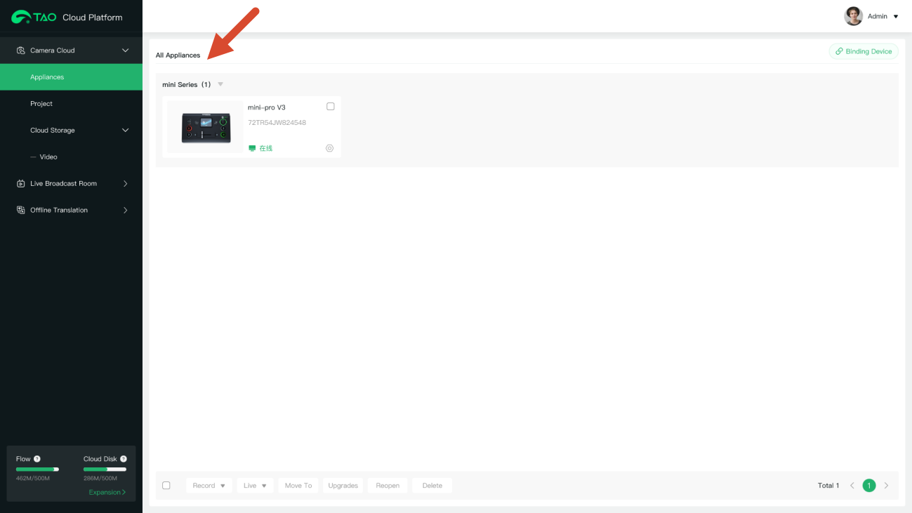
[My Collection] > [Device] > [All Application] >[Binding Devices]

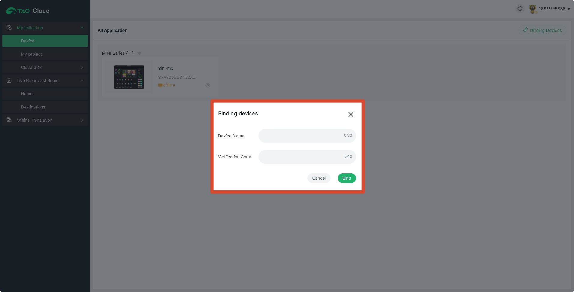
Enter:

  • Device Name
  • Verification Code

Then tap [Bind] to complete device binding.

After binding, the device status can be viewed in [All Application] page.

Unbind the Device

To unbind the device:

Open the [TAO Cloud] page on mini again and select [Rebind] to remove the current binding.

Feature Licensing

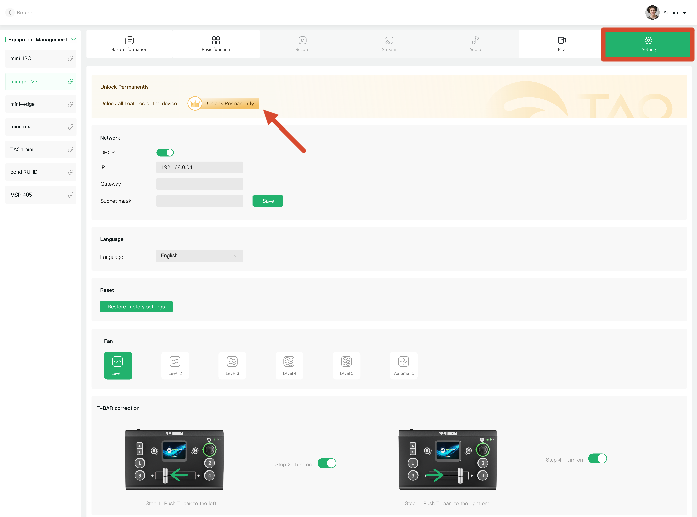
After binding the device, open the mini device management page.

Go to TAO Cloud > [Setting], find [Unlock Permanently]

Purchase Feature Licenses

Select the features you want to activate.

You can also choose [Pay Once, Use Forever]

Tap [Next] to proceed to the payment page.

After payment is completed, the selected features will be unlocked automatically.

2.1.2TAO Remote Control

**๐Ÿ’Ž  **The features described in this chapter are paid features. Please refer to [Activate TAO Cloud Benefits](https://www.yuque.com/rgblink-kb/rlueug/vg2nb6zdh9ylbe45) to unlock them before use.  

```In
addition to local device operation, mini also supports control through TAO Cloud, allowing full device operation without installing additional software.

To access and control device functions through the device management page, the [TAO Remote Control] feature must be activated first.

```tips
๐Ÿ“ข  **Notes**

If [TAO Remote Control] has not been activated, other purchased feature licenses cannot be successfully enabled or used on either TAO Cloud or the device itself.

```After
activating [TAO Cloud Control], simply bind mini to TAO Cloud to:

- View device information
- Switch input sources

We also provide a detailed tutorial video (using mini-ISO as an example) demonstrating signal switching in TAO Cloud.

The workflow shown in the video can be referenced for all mini series products.

[https://www.youtube.com/watch?v=VssE0FBItI4](https://www.youtube.com/watch?v=VssE0FBItI4)

2.1.3Network Streaming

**๐Ÿ’Ž  **The features described in this chapter are licensed features. Please refer to [Activate TAO Cloud Benefits](https://www.yuque.com/rgblink-kb/rlueug/vg2nb6zdh9ylbe45) to unlock them before use.  

```Users
can bind RGBlink devices such as mini to TAO Cloud for efficient content production and live streaming management.

TAO Cloud provides a streamlined streaming platform designed for fast live setup and operation.

mini supports **simultaneous streaming** to up to** 4 platforms**.

Press the [M] button to return to the main menu, then tap [STREAM] to open the streaming configuration page.

![](https://rgblinkw3media9490.blob.core.windows.net/product-images/online-document-images/mini-v3/yuque-1779181170194-d6896d0e.png)

![](https://rgblinkw3media9490.blob.core.windows.net/product-images/online-document-images/mini-v3/yuque-1779181169944-7697330f.png)

#### Network Connection
Before using the streaming function, make sure mini is connected to the network.

Supported connection methods:

- Wired Ethernet connection
- Mobile network sharing

##### Wired Ethernet Connection
Connect mini to a router or network switch using an Ethernet cable.

RGBlink CAT6 Ethernet cable (Product Code No. 940-0001-00-11-0) is recommended.

##### Mobile Network Sharing
```tips
๐Ÿ“ข  **Notes**

Due to ongoing updates to third-party operating systems, the interface layouts and navigation paths described below may differ slightly from the actual interface. 

Please refer to the actual version in use.  

iPhone Network Sharing

Follow these steps:

  1. Connect the iPhone to mini using a standard USB cable through the USB streaming port (labeled WEBCAM)

  1. When the "Trust This Device" prompt appears, tap [Trust]
  2. Open [Settings] > [Personal Hotspot]
  3. Set the Wi-Fi password and enable [Personal Hotspot]
  4. Open Control Center and press the network panel in the upper-left corner
  5. When the hotspot status changes to "Connected", mini has successfully connected to the network.
Android Network Sharing

Follow these steps:

  1. Open [Settings] > [More Settings] > [Developer Options]
  2. Enable [USB Debugging]
  3. Connect the phone to mini using a standard USB cable through the USB streaming port (labeled WEBCAM)

  1. Open [Settings] > [Mobile Network] > [Personal Hotspot] > [Other Sharing Mode]
  2. Enable [Share phone network via USB]

Platform Streaming Setup

This section uses **YouTube **as an example for configuring a streaming destination.

Get the Streaming Address
  • Go to YouTube Studio.
  • Click** Create > Go live**.
  • Copy the Stream key and Stream URL from the stream settings tab.
๐Ÿšจ ** Risk Warning**

**Do not share your stream key with anyone or display it during a live stream.** Doing so may result in unauthorized account access, stream hijacking, or other potential risks and losses.

If your stream key is exposed:

-  Immediately reset the stream key on the corresponding platform.
-  Stop the current live stream.
-  Restart streaming using the new stream key.

```View
[2.4.2 Streaming to Live Platforms](https://www.yuque.com/rgblink-kb/hycqsg/nw1w4iphsnfdzgh9#PtM8f) to check how to get stream key from other platforms.

##### Bind the Device to TAO Cloud
Log in to TAO Cloud and complete device binding.

Make sure the network connection remains stable while receiving the verification code.

##### Import Streaming Information
Paste the streaming address and stream key into TAO Cloud, then click [Distribute].

![](https://rgblinkw3media9490.blob.core.windows.net/product-images/online-document-images/mini-v3/yuque-1779181170785-8d4556f4.png)

##### Start Streaming
Enable the streaming switch from the streaming page or shortcut menu to start streaming.

During streaming, individual platform outputs can be enabled or disabled independently.

Status indicators:

- Solid green: Streaming successfully
- Blinking green: Streaming failed or connection abnormal

![](https://rgblinkw3media9490.blob.core.windows.net/product-images/online-document-images/mini-v3/yuque-1779181170137-43c01238.png)

#### Streaming Quality Settings
To achieve smoother and more stable streaming performance, mini supports bitrate adjustment.

![](https://rgblinkw3media9490.blob.core.windows.net/product-images/online-document-images/mini-v3/yuque-1779181170467-736a85e1.png)

If the network connection is unstable or bandwidth is limited, reducing the bitrate is recommended.

mini also supports:

- Horizontal: Landscape streaming
- Vertical: Portrait streaming

for different platforms and streaming scenarios.

![](https://rgblinkw3media9490.blob.core.windows.net/product-images/online-document-images/mini-v3/yuque-1779181170396-61045dc0.png)

#### PTZ Control During Streaming
To use PTZ control and live streaming simultaneously, ensure that:

- The PTZ camera
- mini device
- The network

are all on the same subnet.

Enabling DHCP on mini is recommended.

If static IP addresses are used, streaming will still function normally as long as there are no IP conflicts.

##### IP Settings
Tap [Settings] > [IP Settings] to open the network configuration page.

mini supports two IP assignment methods:

##### Dynamic IP (DHCP)
Connect mini to a DHCP-enabled router, then:

- Enable DHCP on the router
- Enable DHCP on mini

mini will automatically obtain an IP address.

##### Static IP
If DHCP is not used:

Disable the DHCP option and manually configure:

- IP address
- MASK: Subnet mask
- GW: Gateway

![](https://rgblinkw3media9490.blob.core.windows.net/product-images/online-document-images/mini-v3/yuque-1779181170139-e4a2ad84.png)

2.1.4Record

**๐Ÿ’Ž  **The features described in this chapter are licensed features. Please refer to [Activate TAO Cloud Benefits](https://www.yuque.com/rgblink-kb/rlueug/vg2nb6zdh9ylbe45) to unlock them before use.  

```mini
supports recording video to an external SSD or USB drive through the USB port, providing local recording for live streaming and content creation.  

Supported Specifications

- External SSDs up to 2 TB are supported 
- USB drives up to 64 GB are supported 
- Supported file systems: FAT32 and exFAT 

When a recording file reaches 2 GB, the system automatically saves the recording as a new segment. Each recording segment is approximately 60 minutes long.

#### Connect a Storage Device
Insert the USB drive or external SSD into the USB recording port labeled [RECORD] on the mini panel.

![](https://rgblinkw3media9490.blob.core.windows.net/product-images/online-document-images/mini-v3/yuque-1779181173287-75483c21.png)

#### Format the Storage Device
Before using the recording function, format the USB drive or external SSD first.

1. Press the [M] button to return to the main menu.
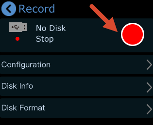
2. Tap [RECORD] to enter the recording settings page. The system will display the current disk status and related settings.

![](https://rgblinkw3media9490.blob.core.windows.net/product-images/online-document-images/mini-v3/yuque-1779181173201-7ce1ba90.png)

3. mini automatically detects whether a storage device is connected. Recording is unavailable if no disk is detected.

![](https://rgblinkw3media9490.blob.core.windows.net/product-images/online-document-images/mini-v3/yuque-1779181173834-7cbf6570.png)

4. Format the disk on the computer. On Windows:
-  Insert the USB drive or external SSD 
-  Right-click the target disk partition and select [Format] 
-  Select [exFAT] as the file system 
-  Set [Allocation Unit Size] to [128 KB] 

e. On the [RECORD] page, tap [Disk Format] > [Yes] to complete disk formatting.

![](https://rgblinkw3media9490.blob.core.windows.net/product-images/online-document-images/mini-v3/yuque-1779181173338-04c6e62f.png)![](https://rgblinkw3media9490.blob.core.windows.net/product-images/online-document-images/mini-v3/yuque-1779181172944-c051faad.png)

```tips
๐Ÿ“ข  **Tips**

If the computer cannot recognize the external SSD after connection, use a dual-USB power cable to provide additional power.  

Recording Configuration

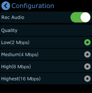
After formatting the disk, tap [RECORD] > [Configure] to set:

  • Audio recording on/off
  • Recording quality level

View Disk Information

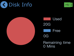
Tap [Record] > [Disk Info] to view:

  • Used disk space
  • Remaining available space
  • Remaining time for recording

Start Recording

Recording can be started from either of the following locations:

  • The recording switch on the [RECORD] page

  • The recording icon on the [Preset Recall Menu] page

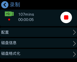
After recording starts, the [Record] page displays:

  • Total recording duration
  • Recording progress

2.1.5Chroma Key

**๐Ÿ’Ž  **The features described in this chapter are licensed features. Please refer to [Activate TAO Cloud Benefits](https://www.yuque.com/rgblink-kb/rlueug/vg2nb6zdh9ylbe45) to unlock them before use.  

```mini
supports chroma keying, allowing solid-color backgrounds to be removed and composited with other video sources for virtual scenes and similar applications.

Chroma key parameters can be configured through the desktop control software for advanced adjustments or directly on the device for quick setup.

#### Enable Chroma Key
1.  Press the [M] button to return to the main menu. 
2.  Tap the [KEY] icon to enter the chroma key settings page. 

![](https://rgblinkw3media9490.blob.core.windows.net/product-images/online-document-images/mini-v3/yuque-1779181175192-a904f565.png)

3.  Select On or Off. 

![](https://rgblinkw3media9490.blob.core.windows.net/product-images/online-document-images/mini-v3/yuque-1779181174596-b9009f7b.png)

#### Adjust Chroma Key Parameters
1.  The default chroma key color is green (green screen). Different color options can be selected on the touchscreen. 
2.  Tap the [-] or [+] buttons to fine-tune the chroma key parameters. 

Default parameter values:

-  Max Limit: 1232 
-  Min Limit: 560 
-  Margin: 602 

![](https://rgblinkw3media9490.blob.core.windows.net/product-images/online-document-images/mini-v3/yuque-1779181174590-8d877b25.png)

![](https://rgblinkw3media9490.blob.core.windows.net/product-images/online-document-images/mini-v3/yuque-1779181176502-c498fb90.png)

#### Adjust the Layout
Tap [ Adjust] to enter the layout settings page.

On this page:

-  Tap [A/B] to select the main screen or PiP screen 
-  Press [1], [2], [3], or [4] on the main panel to switch input sources 

Default configuration:

-  PiP screen: Input [4] 
-  Main screen: Input [1] 

Input sources can be changed based on actual requirements.

Use the X/Y knobs on the main panel to adjust the screen size and position.

All changes are saved automatically to the current scene in real time.

![](https://rgblinkw3media9490.blob.core.windows.net/product-images/online-document-images/mini-v3/yuque-1779181174870-29310c7d.png)

#### Save Chroma Key Settings
Chroma key settings can be saved directly on the device.

The next time chroma key is enabled through:

-  Desktop control software 
-  The device itself 

the previously saved parameter settings can be recalled automatically.

2.1.6PTZ

**๐Ÿ’Ž  **The features described in this chapter are licensed features. Please refer to [Activate TAO Cloud Benefits](https://www.yuque.com/rgblink-kb/rlueug/vg2nb6zdh9ylbe45) to unlock them before use.  

```mini
supports PTZ camera control through the IP VISCA protocol, including:

-  Pan and tilt control (X/Y axis) 
-  Lens zoom control 
-  Manual and auto focus 
-  PTZ preset recall 

mini also supports saving PTZ camera position and zoom status for quick recall later.

PTZ scenes on mini save both PTZ parameters and the corresponding input source. When a PTZ scene is recalled, the system automatically switches to the associated camera input.

```info
mini v3 currently supports PTZ cameras using the** VISCA** protocol.

Open the PTZ Control Menu

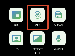
  1. Press the [M] button to return to the main menu.
  2. Tap [PTZ] to enter the PTZ control page.

Select a PTZ Camera

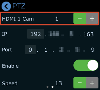
  • Press [1], [2], [3], or [4] to select the corresponding input source.
  • Tap [-] or [+] next to the camera icon to switch between different video sources.

The selected camera becomes the active PTZ camera for control.

Camera Port Settings

Before controlling the camera with mini, ensure the camera port number is set to 1259.

If the camera port is not 1259:

  • Refer to the camera user manual
  • Enter the correct port number on the PTZ settings page

This ensures proper PTZ communication.

We recommend using the RGBlink vue series PTZ cameras.

Network Requirements

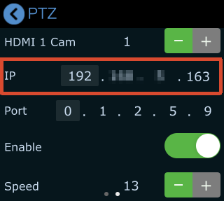
mini and the PTZ camera must be on the same subnet.

The first three segments of the following IP addresses must match:

  • mini IP address
  • PTZ camera IP address

The mini IP address can be modified in:

  • [PTZ] menu
  • [SETTINGS] > [IP Setting]

When modifying the IP address, use the X/Y knobs on the front panel to select and adjust each IP address segment.

PTZ Preset Control

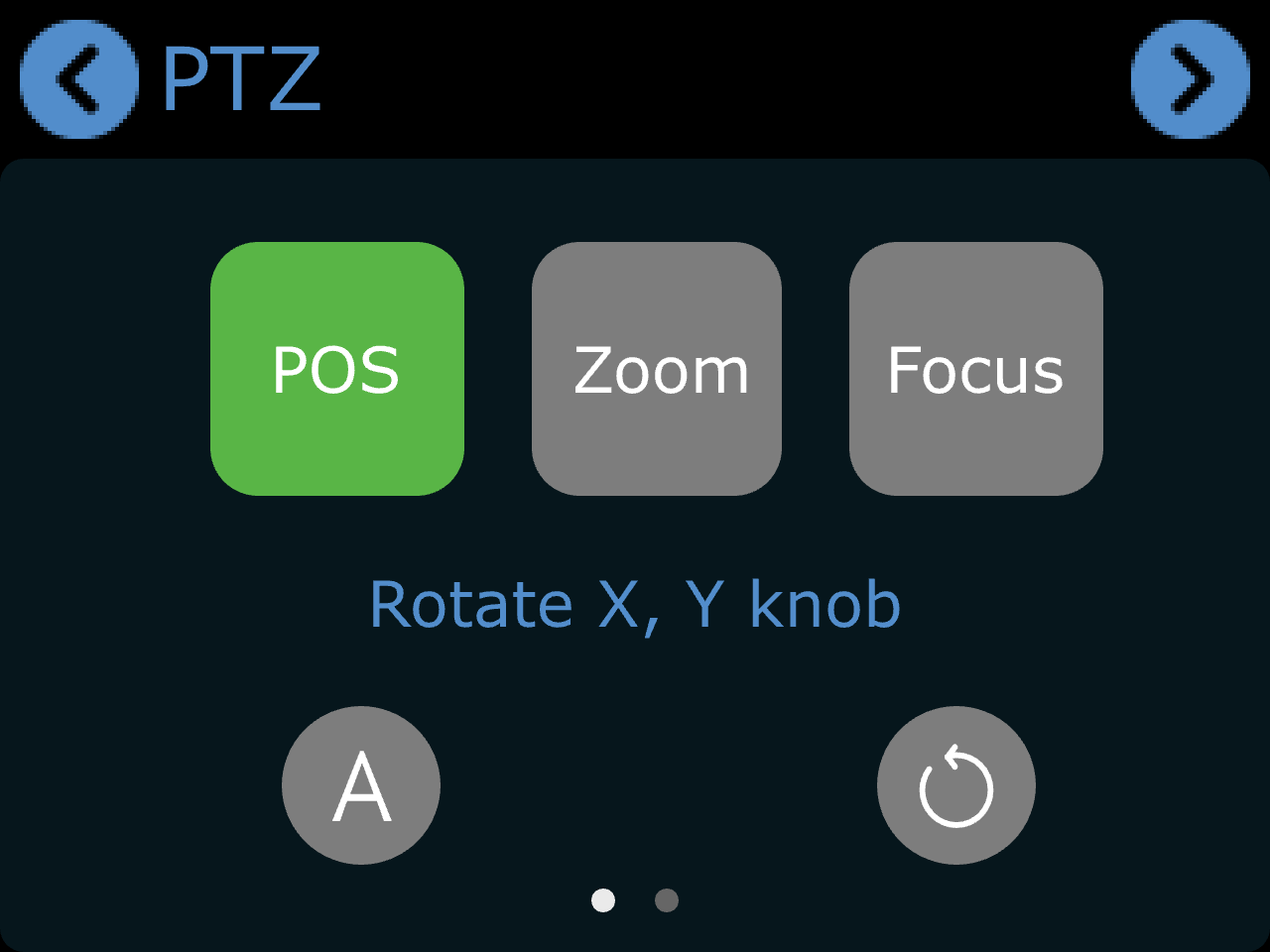
Adjust Position / Zoom / Focus

After PTZ is enabled:

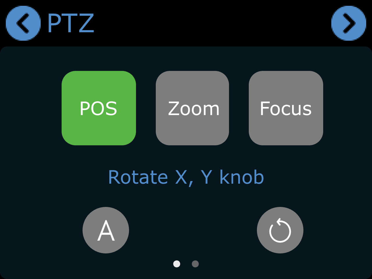
  • Tap [POS] and use the X/Y knobs on the main panel to control camera movement
  • Tap [Focus] and use the X knob on the main panel for manual focus
  • Tap [A] icon to enable auto focus
Adjust PTZ Speed
  1. Tap [POS].
  2. Tap the next-page button to enter the detailed settings page.
  3. Adjust the PTZ movement speed in the [Speed] section.
  4. Supported speed levels: 17, 14, 11, 8, 5, 2
Reset PTZ Settings

Tap the reset icon on the screen to restore PTZ parameters to default settings.
2.2USB Port Capture and Output

๐Ÿ“ข  **Notes**

The screenshots in this document may differ from the current software version. 

Actual interface layout and wording may vary, but the operation flow remains the same.

Please refer to the version currently in use.

```The
USB port labeled [WEBCAM] supports USB video capture.

Users can capture video from mini to a computer and stream through third-party software such as OBS to platforms including:

-  Facebook 
-  YouTube 
-  Zoom 
-  Twitter/X 
-  Other streaming platforms 

#### OBS Streaming
mini is compatible with various third-party streaming applications. We recommend using OBS.

Download OBS from: [OBS Studio](https://obsproject.com/download?utm_source=chatgpt.com)

Install the software and update it to the latest version before use.

##### Add Video Capture Device
1.  Click the [+] icon in the Sources panel. 

![](https://rgblinkw3media9490.blob.core.windows.net/product-images/online-document-images/mini-v3/yuque-1779181179659-5490f75a.png)

2.  Select [Video Capture Device]. 

![](https://rgblinkw3media9490.blob.core.windows.net/product-images/online-document-images/mini-v3/yuque-1779181179386-ffcb9ddc.png)

3.  Select [RGBlink USB 3.0 Capture] as the capture device. 
4.  Set [Video Format] > [YUY2]. 

![](https://rgblinkw3media9490.blob.core.windows.net/product-images/online-document-images/mini-v3/yuque-1779181179397-335e1482.png)

```tips
**๐Ÿ“ข  Notes **

If the YUY2 format is unavailable, check the USB connection:

-  Ensure the device is connected to a USB 3.0 port 
-  Use a USB 3.0 cable 
-  USB 3.0 ports are typically blue, while USB 2.0 ports are usually black 

Audio Settings

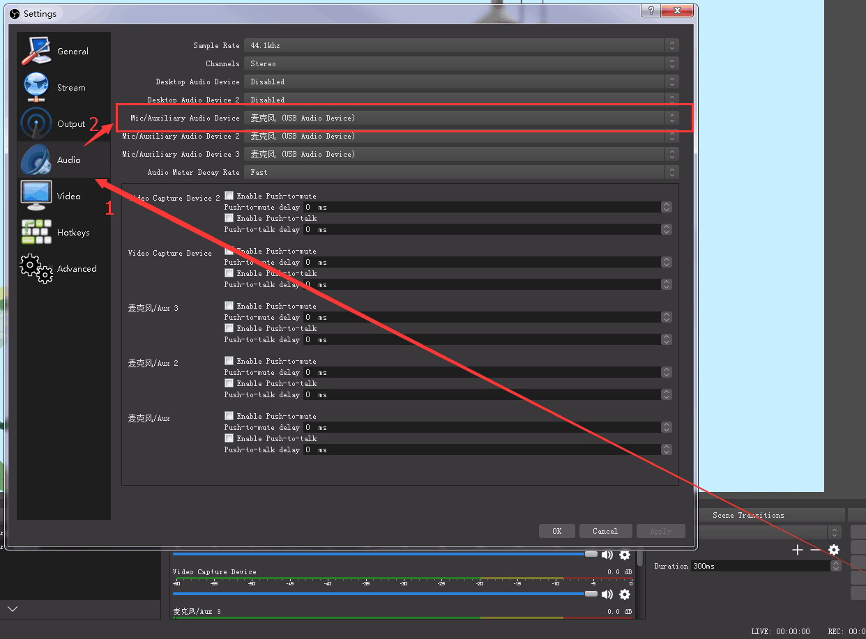
If no audio is detected during streaming:

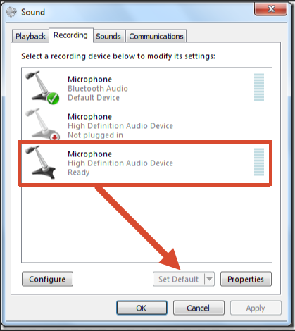
  1. Confirm the audio source on the device is configured correctly (Set Default).

  1. In OBS, go to [Settings] > [Audio]. Select the correct device [Mic/Auxiliary Audio Device].
Synchronize Video with External Audio

If the video source does not contain embedded audio and external audio is used separately, synchronize the audio and video using the following steps.

  1. Go to [Settings] > [Audio] > [Mic/Auxiliary Audio Device] and select the audio source.

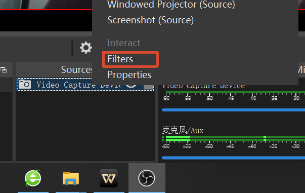
  1. In the Sources panel, right-click [Video Capture Device], then select [Filters].

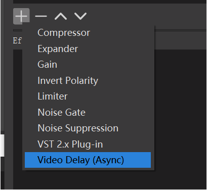
  1. Under [Audio/Video Filters], click [+] and select [Video Delay (Async)].

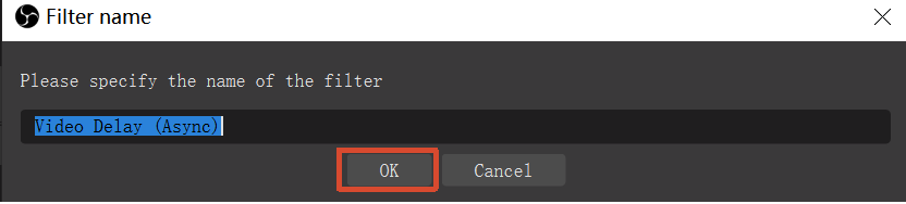
  1. Enter a filter name if needed, then click [OK].

  1. Enter the delay value in milliseconds (ms).
    Adjust the value until the audio and video are synchronized.

Streaming Settings
  1. Obtain the RTMP URL and Stream Key from the streaming platform.
  2. Copy the RTMP URL and Stream Key.
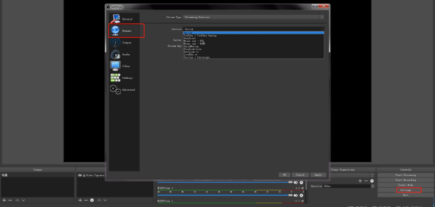
  3. In OBS, go to [Settings] > [Stream].
  4. Select the streaming type:
  • [Streaming Service]
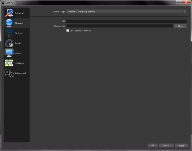
  • [Custom Streaming Server]

If the platform is listed under [Service], select it directly.

If using a custom server:

  • Enter the RTMP URL in [Server]/[URL]

  • Enter the Stream Key in [Stream Key]
  1. Click [Start Streaming].
  2. Return to the streaming platform and confirm the live stream is active.

vMix Streaming

 ๐Ÿ“ข**  Notes**

vMix cannot automatically detect the output resolution of mini.  
Each time the output resolution of mini is changed, the video preview in vMix may freeze. Re-select [RGBlink USB3.0 Capture] and manually set the current output resolution of mini to restore normal video display.  

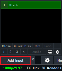
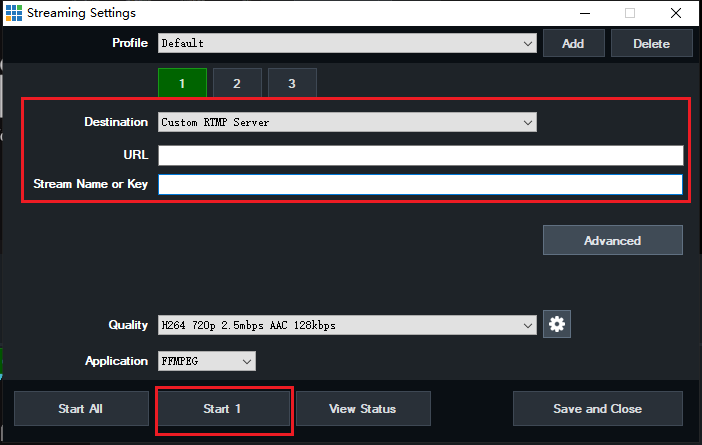
  1. Click an empty input area, then click [Add Input].

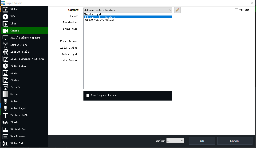
  1. Select [Camera] > [Camera] > [RGBlink USB3.0 Capture].

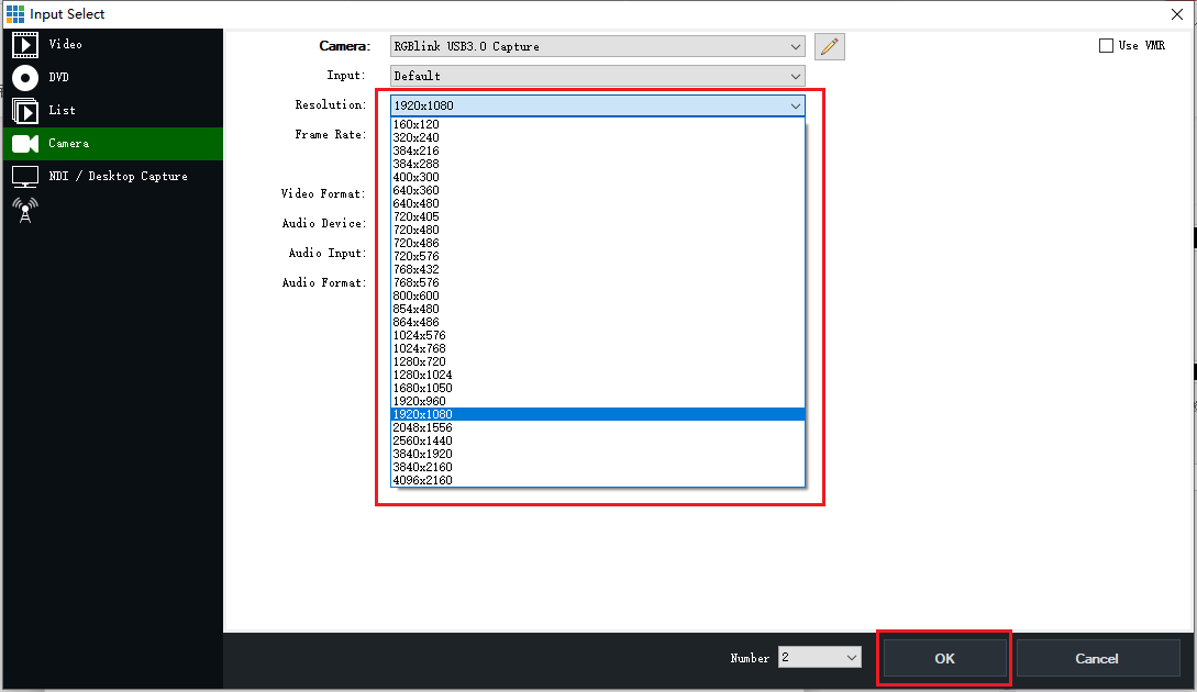
  1. Select the same resolution as the mini output resolution, then click [OK].

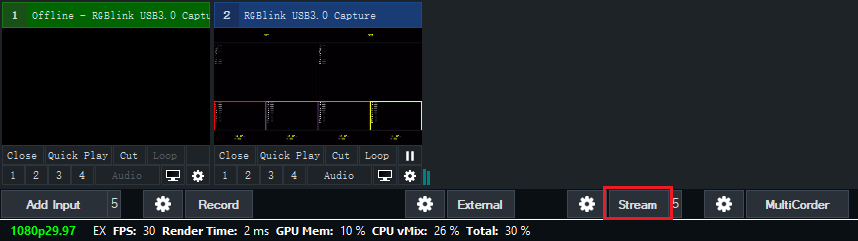
  1. Click the stream settings button.

  1. Enter the streaming URL and Stream Key.
  2. Click [Start 1] to begin streaming.

Facebook Streaming

Refer to the actual Facebook Live interface for streaming setup.

Official Guide link: https://www.facebook.com/business/help/165076674943644?id=1123223941353904

Zoom Streaming

Refer to the actual Zoom interface for streaming setup.

Official Guide link: https://support.zoom.com/hc/en/article?id=zm_kb&sysparm_article=KB0064210

3Upgrade

mini supports online upgrades.

Before You Start

  1. Connect the mini to the computer using an Ethernet cable.
  2. Open the network settings on the computer and ensure the computer and mini are connected to the same LAN. DHCP is recommended for automatic IP address assignment to ensure proper communication.

Upgrade Procedure

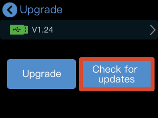
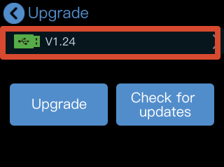
  1. Go to [SETTINGS] > [Upgrade] to open the upgrade page.

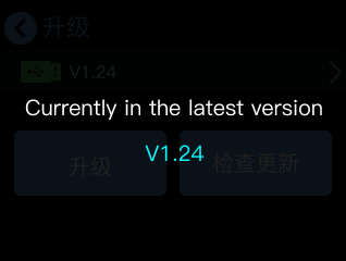
  1. If the device is already running the latest version, tap [Check for Updates], the page will display [Currently in the latest version] along with the current version number.

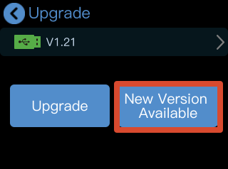
  1. If a new version is available, the page will display [New Version Available].

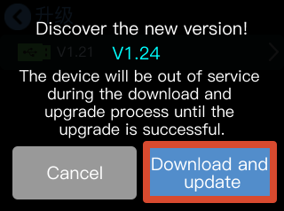
  1. Tap [New Version Available] to view the latest version information. Then tap [Download and Update] to download the upgrade package.

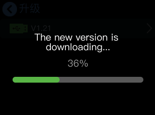
  1. The download progress will be displayed during the process.
    The download may take approximately 10 minutes, depending on the network speed.

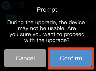
  1. After the download is complete, tap [Confirm] to start the upgrade.

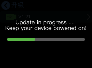
  1. The upgrade progress bar will be displayed during the upgrade process. Once the upgrade is complete, the device will restart automatically.

**๐Ÿ“ข  Important**

**Do not** power off the device during the upgrade process. 

Otherwise, the upgrade may fail.

  1. After the device restarts, the updated version number will be displayed on the [Upgrade] page.

5Technical Support

6Revision History

VersionDateDescriptionAuthor
V1.02025-07-11Release mini.Alyssa
V1.12025-08-04Modify the premium function range.Alyssa
V1.22025-10-14Enrich the Support SectionAlyssa
V1.32026-05-08Add FAQ items and update related details.Alyn

About Us / Find Support

Xiamen RGBlink Science & Technology Co., Ltd. designs and manufactures professional video processing, switching, streaming and LED display control products for live events, broadcast, education and fixed installations.

Need help?

Choose one of the following support options:

  • AI Support Search (Recommended): Visit Support > Support proStream/proAV/proEvents on the RGBlink official website and ask the RGBlink AI Bot for quick answers.
  • FAQs: Visit Support > Support proStream/proAV/proEvents on the RGBlink official website and browse Knowledge Menu > FAQ.
  • Contact Technical Support: Visit the Technical Support page of this manual or the RGBlink official website for our contact details.

Document image

RGBlink

www.rgblink.com

ยฉ Copyright Xiamen RGBlink Science & Technology Co Ltd