Export PDF

RGBlink
MSP 325N HDMI to H.265 Encoder

User Manual

MSP 325N HDMI to H.265 Encoder

MSP 325N User Manual

601-0325-05-1

RGBlink

www.rgblink.com

November 2026

1.1Technical Specifications

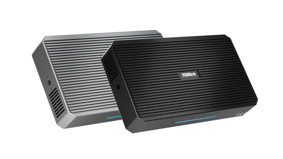
Document image Document image The actual product color may vary. Color versions are shipped at random.

UHD 4K HDMI Video Encoder/Decoder

Key Features

  • Small and compact, easy to carry
  • H.265/H.264 high-performance encoding and decoding capability
  • Input resolution up to 4K@60Hz
  • HTTP/SRT/RTMP/RTSP/NDI protocols supported
  • Multi-stream decoding capability
  • Feature with one USB interface for recording
  • PoE & DC 12V power supply +
  • TAO Cloud integrated control
  • Low latency transmission

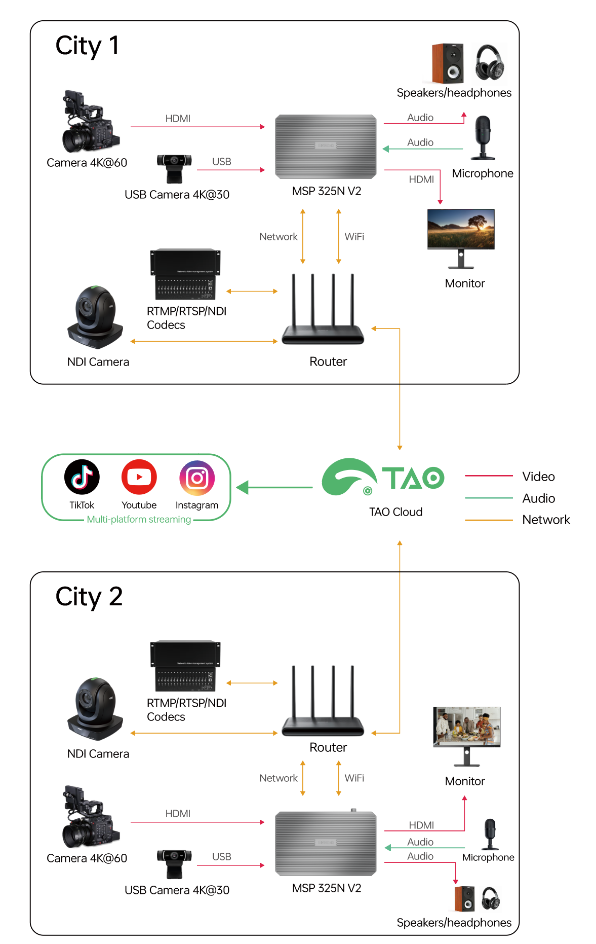
Application

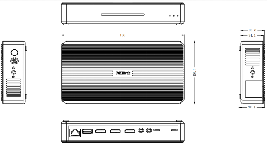
Dimensions (mm)

Connectors

ItemDescription
InputHDMI 2.01 × HDMI-A
OutputHDMI 2.01 × HDMI-A (Loop)
HDMI 2.01 × HDMI-A
CaptureLine-in1 × 3.5mm Audio Jack
Line-out1 × 3.5mm Audio Jack
Ethernet / Upgrade / StreamUSB1 × USB-A
PowerUSB1 × USB-C
InputLAN1 × RJ45
OutputPower1 × Type-C

Performance

ItemDescription
Input ResolutionHDMI 2.0720p@50, 1920 × 1080i@50/60, 1920 × 1080p@24/30/50/60, 3840 × 2160@30/50/60
FormatRGB/YUV 4:2:2 8bits
DeinterlacingYES
Embedded AudioYES
HDCP2.2/1.X
Output ResolutionHDMI 2.0720p@50, 1920 × 1080i@50/60, 1920 × 1080p@24/30/50/60, 3840 × 2160@30/50/60
Audio InputLINE INAnalog Audio Input
Audio OutputLINE OUTExternal Active Speakers Supported
RecordVideoH.264, up to 32Mbps
AudioAAC, up to 48Kbps
StorageBuilt-in Storage128GB
EncodingPerformanceH.264/H.265
ProtocolsHTTP/SRT/RTMP/RTSP/NDI
ResolutionUp to 3840 × 2160p@60
Decoding1×4K@60Hz, 2×4K@30Hz, 4×2K@60Hz

Power

ItemDescription
PD Input12V/3A

Working Environment

ItemDescription
Temperature0℃~55℃
Humidity5%~85% RH

Physical

ItemDescription
WeightNet Weight0.33kg
Package Weight0.96kg
DimensionsNet Dimension (no mounting ear)139mm × 99.5mm × 27.6mm
Package Dimension255mm × 147mm × 88mm

Order Codes

Product CodeItem
410-5513-06-2MSP 325N V2

1.2FCC/Warranty

Federal Communications Commission (FCC) Statement

This equipment has been tested and found to comply with the limits for a class A digital device, pursuant to Part 15 of the FCC rules. These limits are designed to provide reasonable protection against harmful interference when the equipment is operated in a commercial environment. Operation of this equipment in a residential area may cause harmful interference, in which case the user will be responsible for correcting any interference.

Guarantee and Compensation

RGBlink provides a guarantee relating to perfect manufacturing as part of the legally stipulated terms of guarantee. On receipt, the purchaser must immediately inspect all delivered goods for damage incurred during transport.

The period of guarantee begins on the date of transfer of risks, in the case of special systems and software on the date of commissioning, at latest 30 days after the transfer of risks. In the event of justified notice of compliant, RGBlink can repair the fault or provide a replacement at its own discretion within an appropriate period. If this measure proves to be impossible or unsuccessful, the purchaser can demand a reduction in the purchase price or cancellation of the contract.

If the purchaser or a third party carries out modifications or repairs on goods delivered by RGBlink, or if the goods are handled incorrectly, in particular if the systems are commissioned operated incorrectly or if, after the transfer of risks, the goods are subject to influences not agreed upon in the contract, all guarantee claims of the purchaser will be rendered invalid. Not included in the guarantee coverage are system failures which are attributed to programs or special electronic circuitry provided by the purchaser, e.g. interfaces. Normal wear as well as normal maintenance are not subject to the guarantee provided by RGBlink either.

The environmental conditions as well as the servicing and maintenance regulations specified in this manual must be complied with by the customer.

1.3Revision History

VersionDateDescriptionAuthor
V1.02026-04-28First release.Alyn

1.4Operators Safety Summary

The general safety information in this summary is for operating personnel.

Do Not Remove Covers or Panels

There are no user-serviceable parts within the unit. To avoid personal injury, do not remove the top cover. Do not operate the unit without the cover installed.

Use the Proper Power Cord

Use only the standard power cord for your product.

Do Not Operate in Explosive Atmospheres

To avoid explosion, do not operate this product in an explosive atmosphere.

1.1About the Product

The MSP 325N V2 is a high-performance, compact streaming processor that combines exceptional portability with powerful features. Its sleek, small design makes it easy to carry and versatile enough for various scenarios. Supporting H.265/H.264 high-efficiency encoding to ensure excellent video quality while minimizing bandwidth usage and decoding capability (Multi-stream decoding: 1×2160p60 + 2×2160p30 + 4×1080p60).

The MSP 325N V2 handles input resolutions up to 4K@60Hz, making it ideal for high-resolution video processing. It is compatible with a range of streaming protocols including HTTP, SRT, RTMP, RTSP, and NDI, catering to diverse streaming needs.

Additionally, the MSP 325N V2 also features USB connectivity for video recording, allowing users to replay content anytime, offering enhanced flexibility. With PoE power support and TAO cloud integration control, installation and management are simplified. The low-latency transmission makes the MSP 325N V2 an ideal choice for live streaming, conference, and other video IP transmission applications.

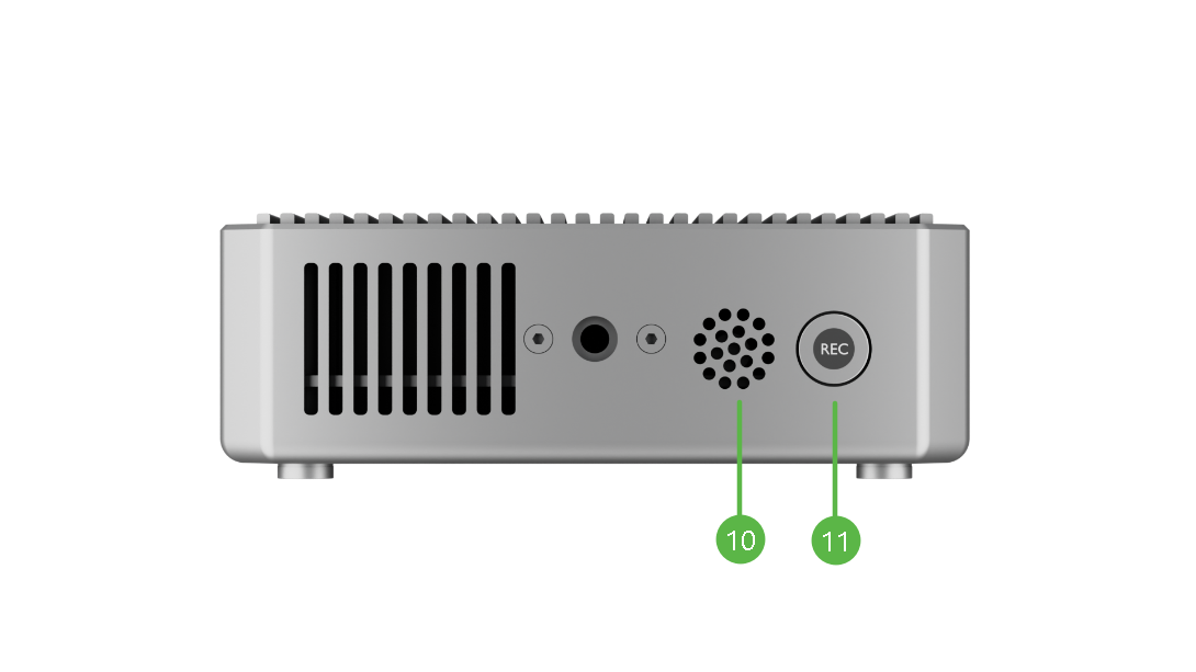
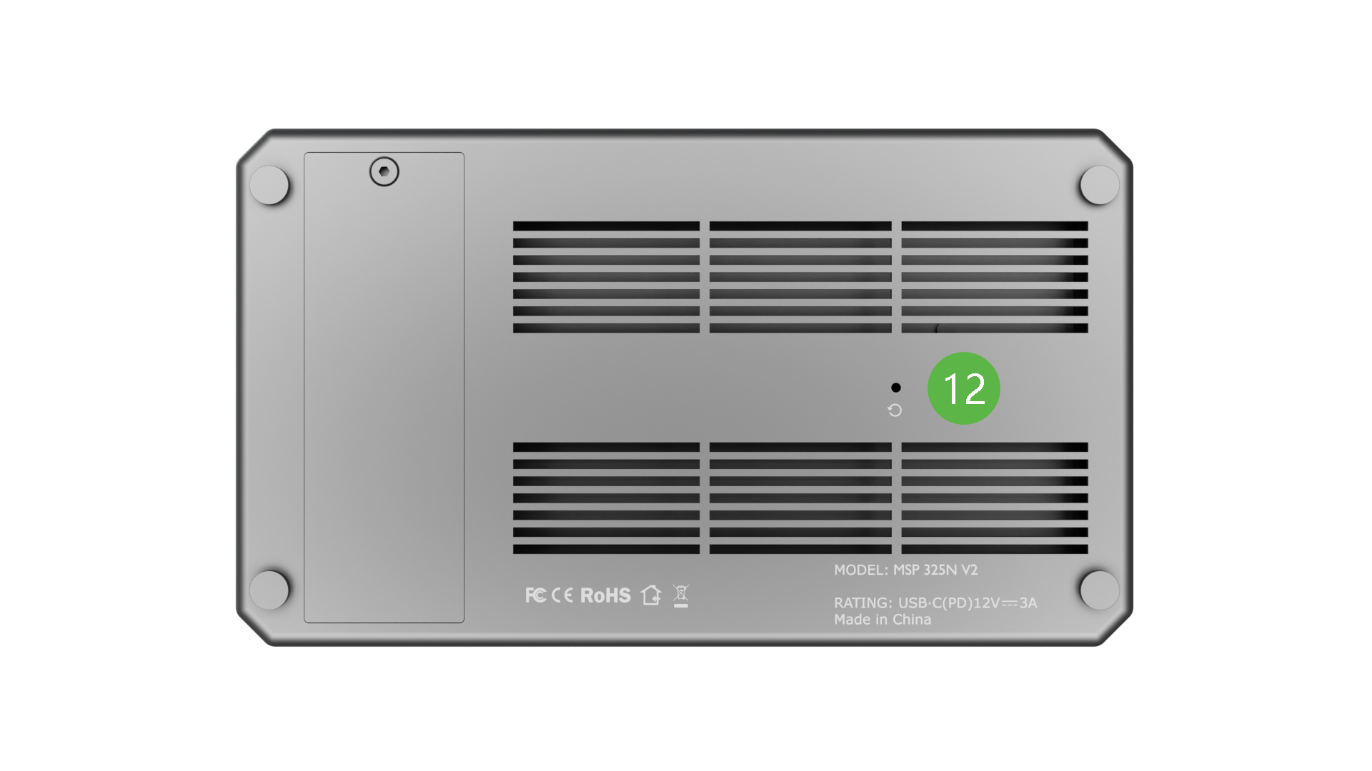
1.3Ports Info

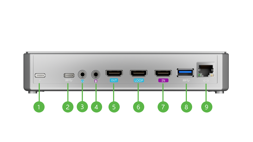
Diagram and description of the device
云宝背视图
云宝右视图
NO.InterfaceDesc.Function
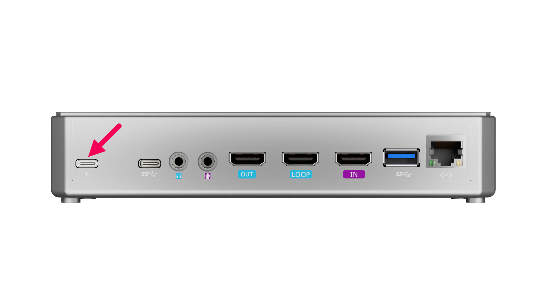
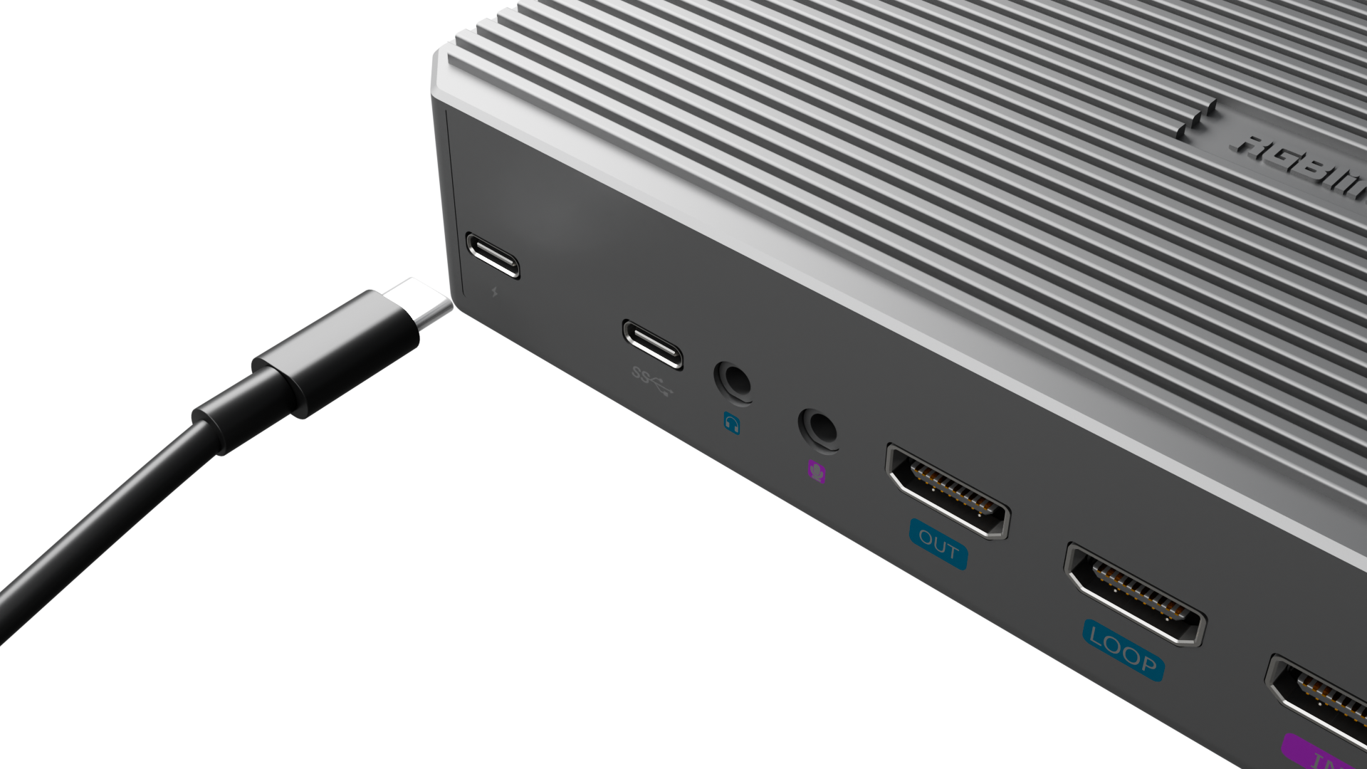
❶PowerSupport PD protocol12V/3A (minimum)
❷USB-CType-CStandard interface supporting UVC audio and video.
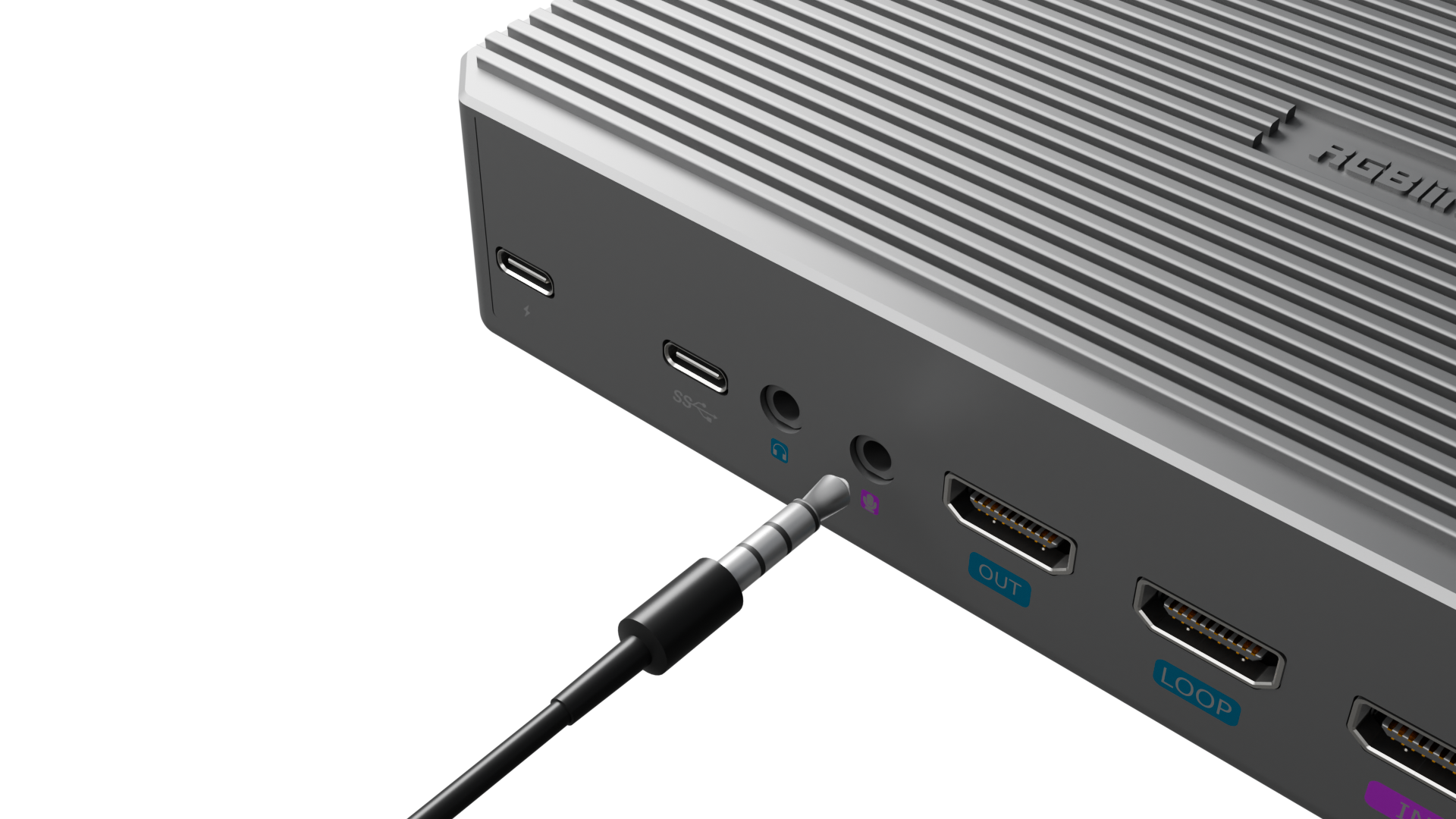
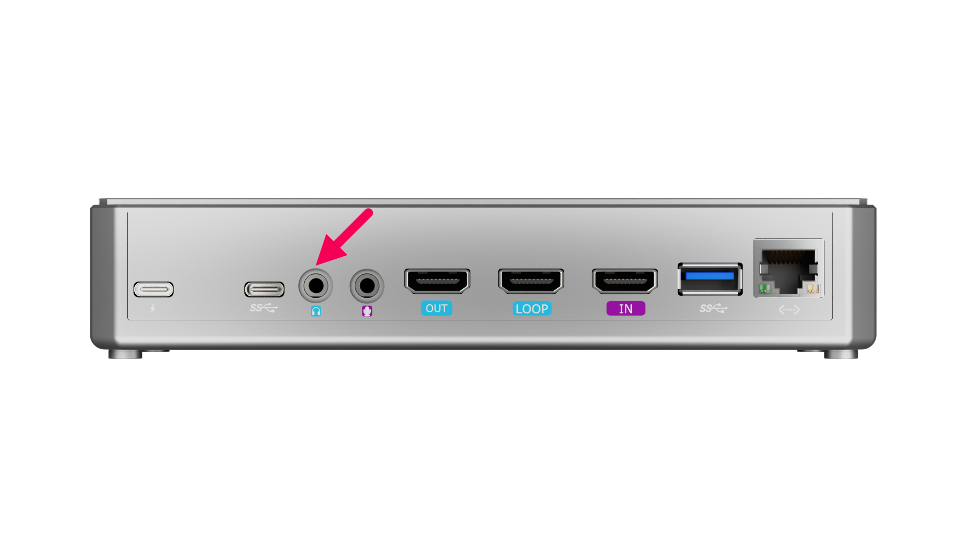
❸Line-out3.5mmMonitor final PGM audio via headphones or speakers.
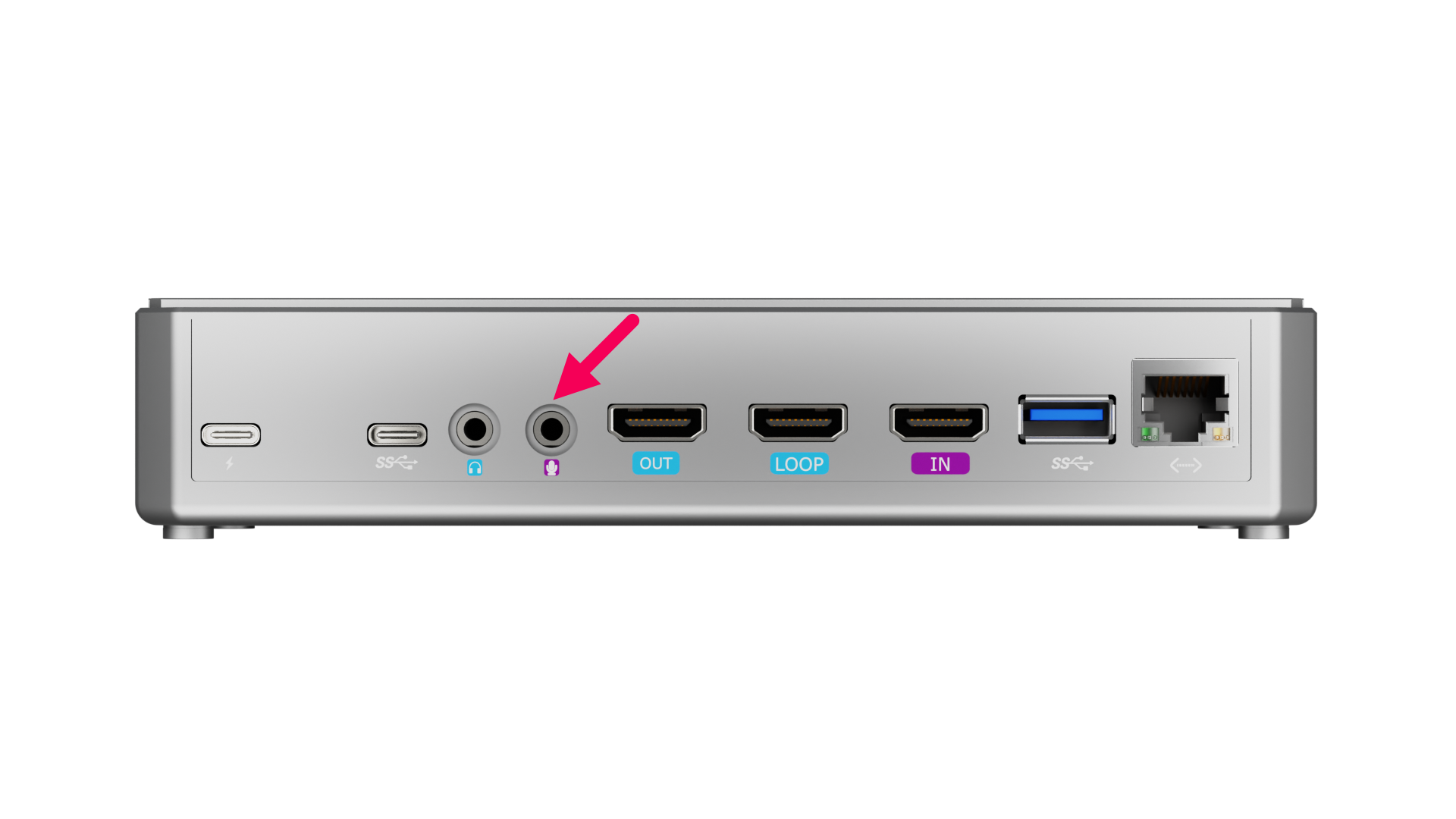
❹Line-in3.5mmConnect powered microphones and similar devices.
❺HDMI OUT/Switch between HDMI/UVC inputs; connect monitors for PGM preview.
❻HDMI LOOP/Pass original HDMI signals to secondary monitors or capture cards.
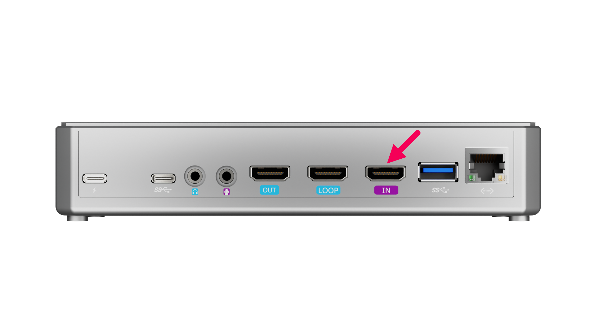
❼HDMI IN/Connect HD cameras, computers, etc.
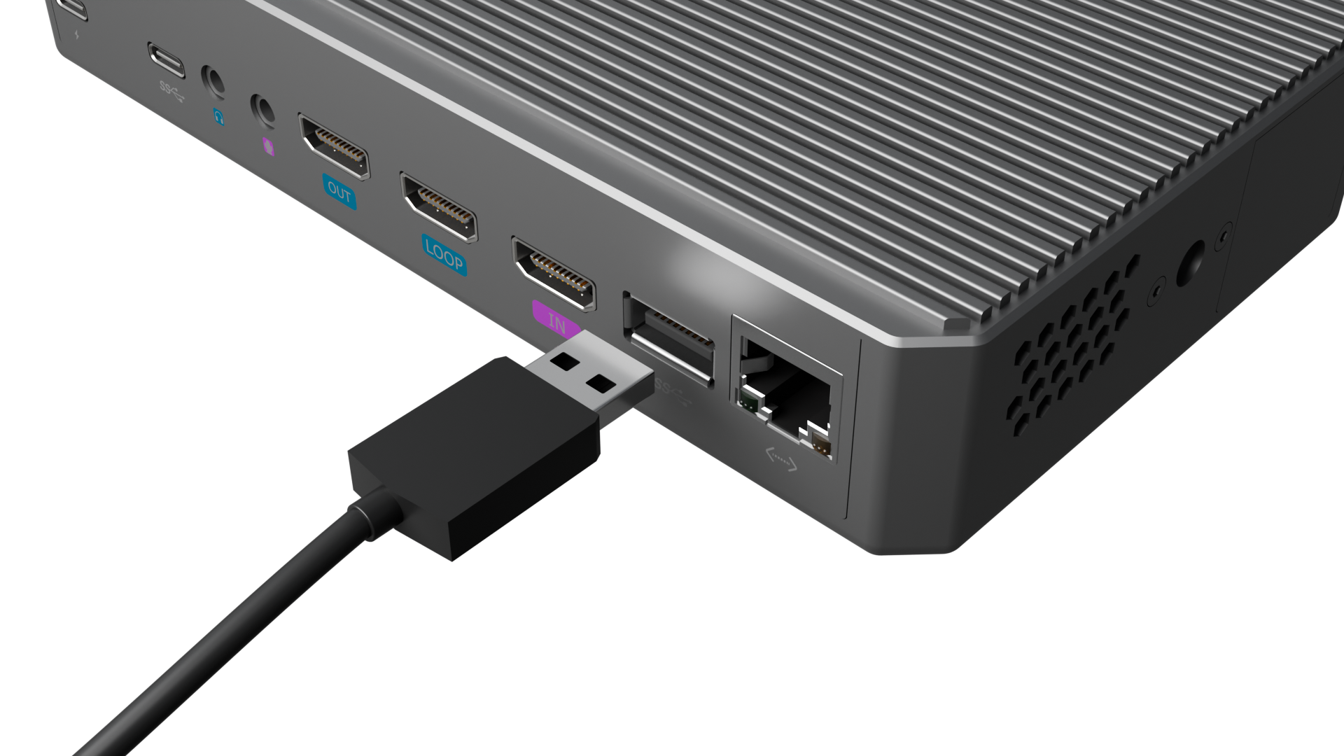
❽USB-AType-AConnect USB flash drives, external hard drives, and other storage devices for data storage and transfer.
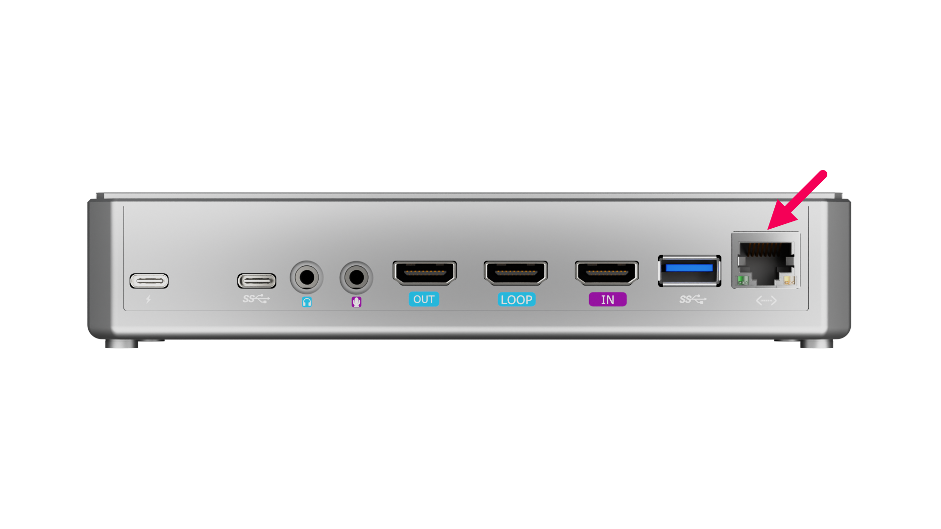
❾LAN/Connects to a network for live streaming and online updates. Support for Power over Ethernet (PoE).
❿MICBuilt-in MicrophoneSensitivity: -36 dBV/Pa Pickup range: 5m
⓫RECDisabled
⓬RESET//

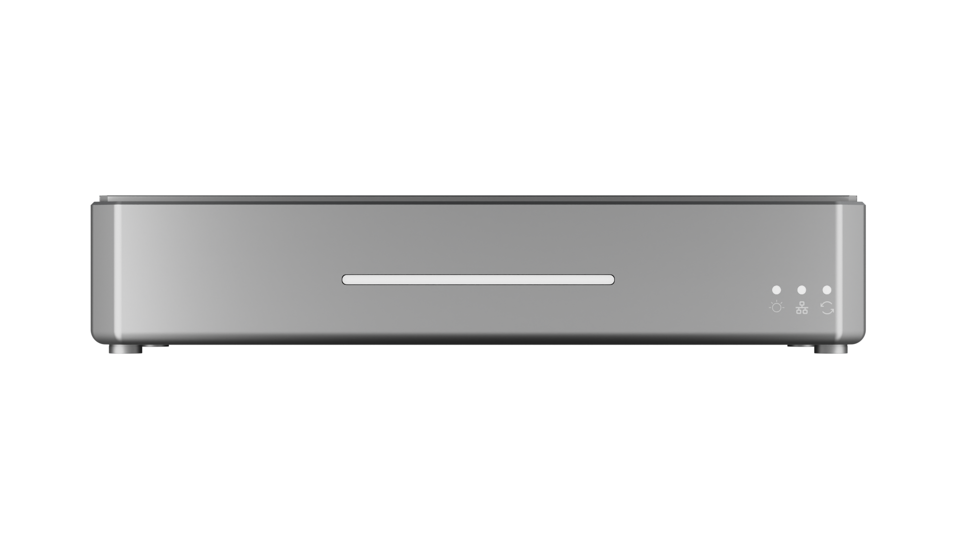
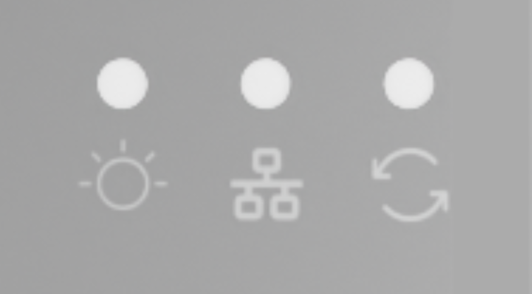
1.4Status Indicators

e

The Front Panel
IndicatorColorStatusDesc.
PowerWhiteSolidPower connected
OffPower off or malfunction
LinkWhiteSolidNetwork connected
OffNetwork error or disconnected
RunWhiteBlinkNormal operation
SolidStarting up
OffDevice malfunction or not started
Light BarWhiteOff/

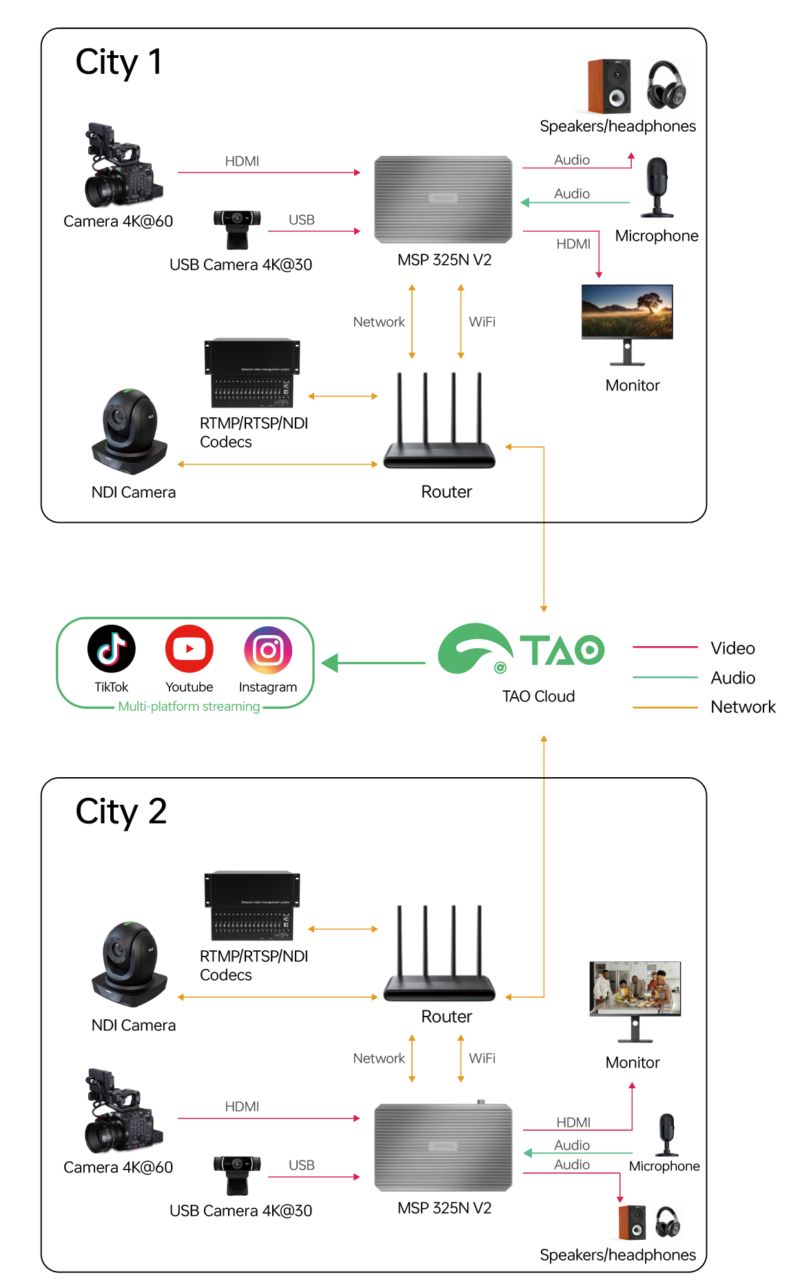
2.1Application

2.2Device Connection

Connect Power

Connect the power cable to turn on the device automatically.

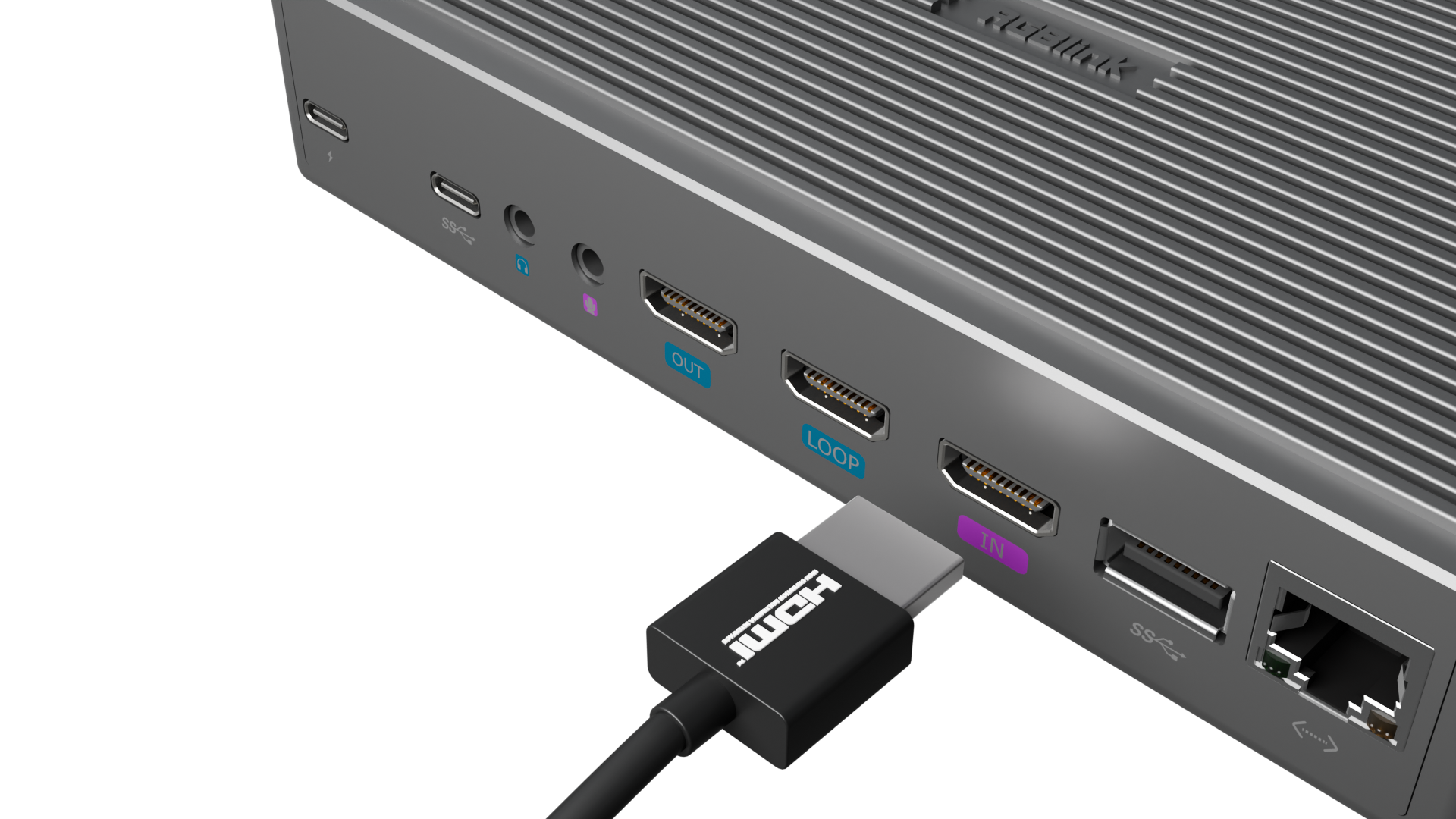
Connect HDMI Input Cable

Connect HD cameras, computers, and other input sources with HDMI interfaces.

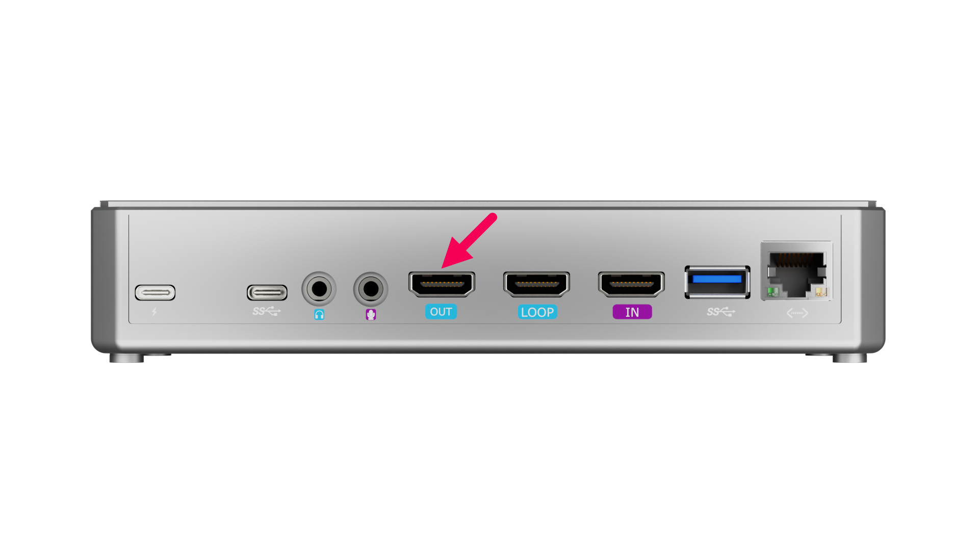
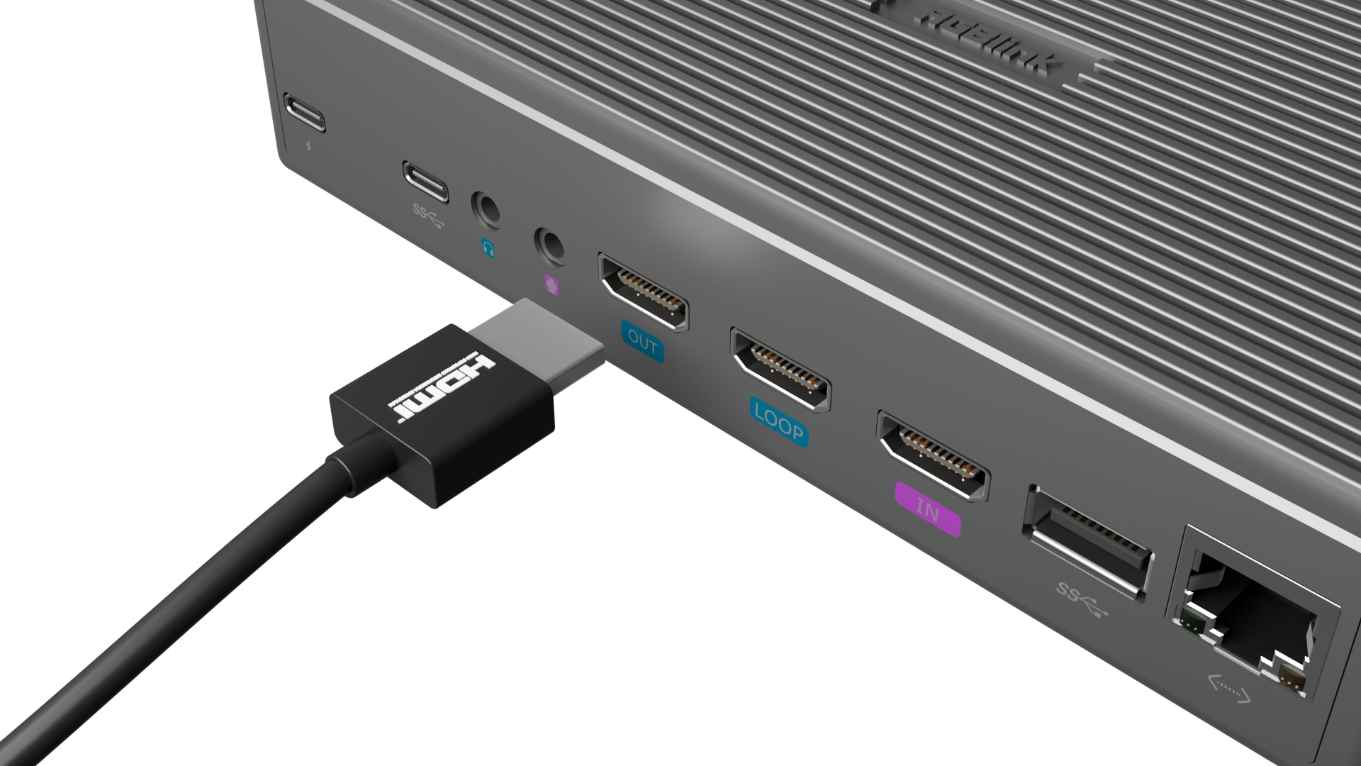
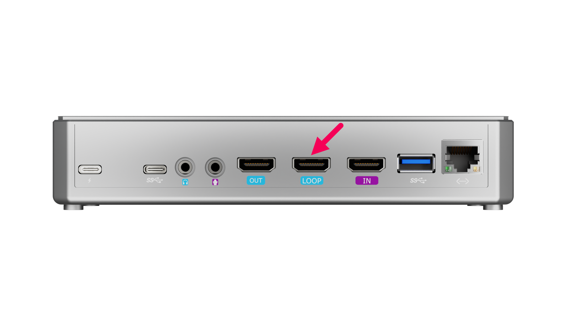
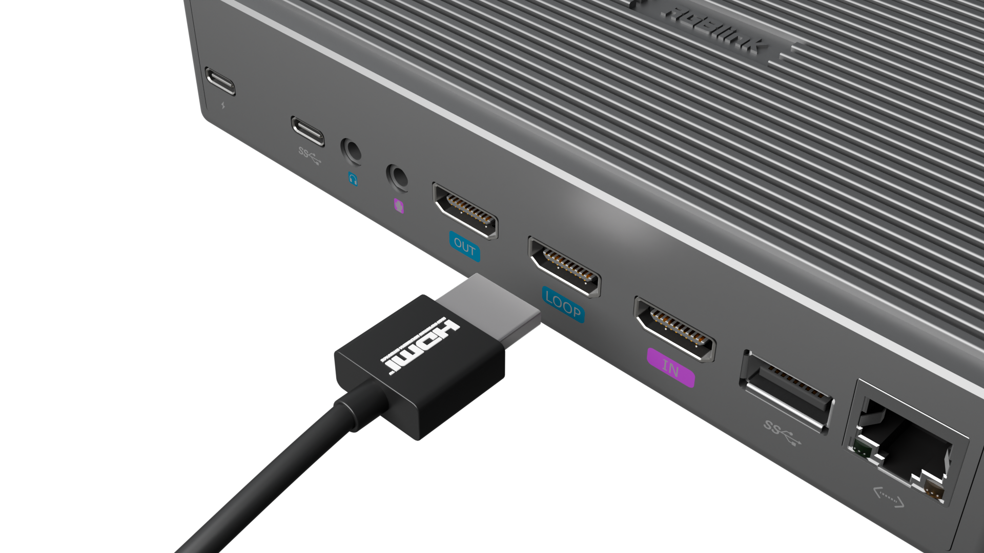
Connect HDMI Output Cable

HDMI OUT: Use an HDMI cable to connect the MSP 325N V2 to a monitor as the main output.

HDMI LOOP: Use another HDMI cable to connect the MSP 325N V2 to a monitor, looping the HDMI input signal.

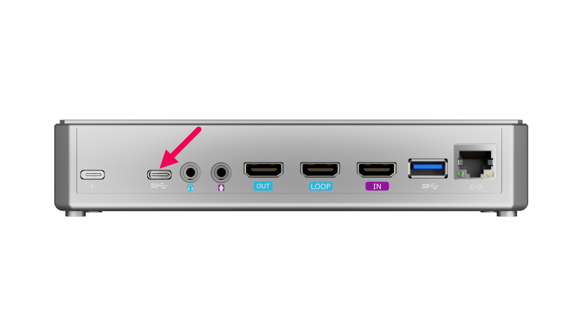
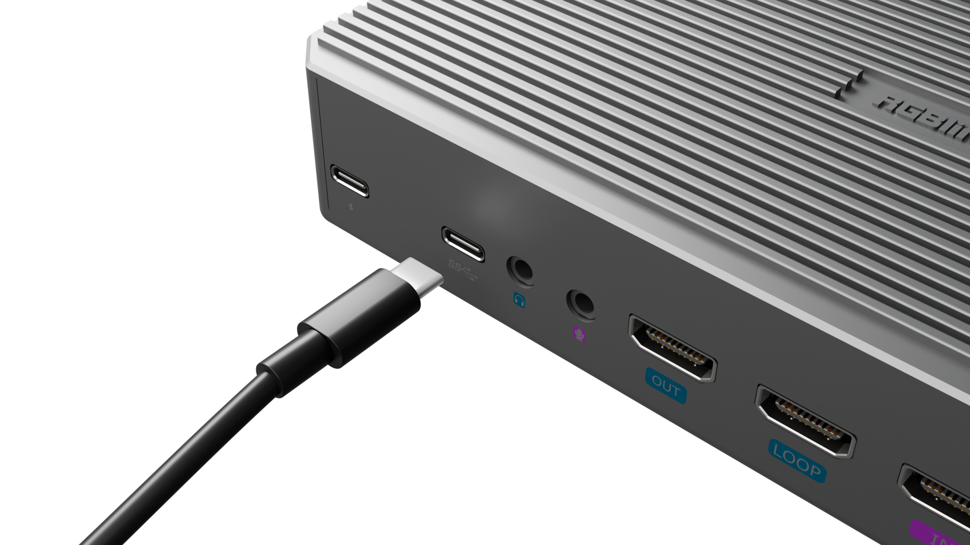
Connect USB-C Cable

Use a data cable supporting the UVC protocol to connect a USB input camera.

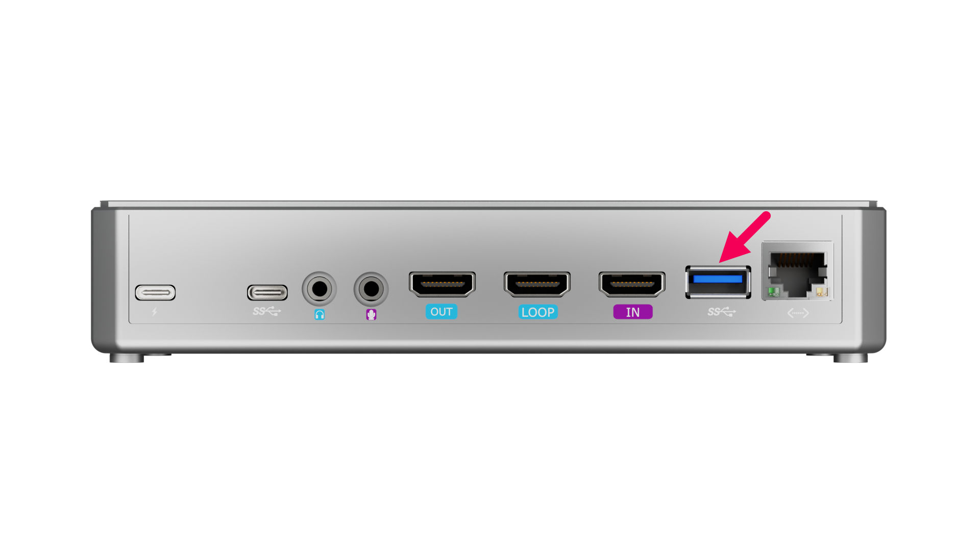
Connect USB-A Cable

Connect a USB camera.

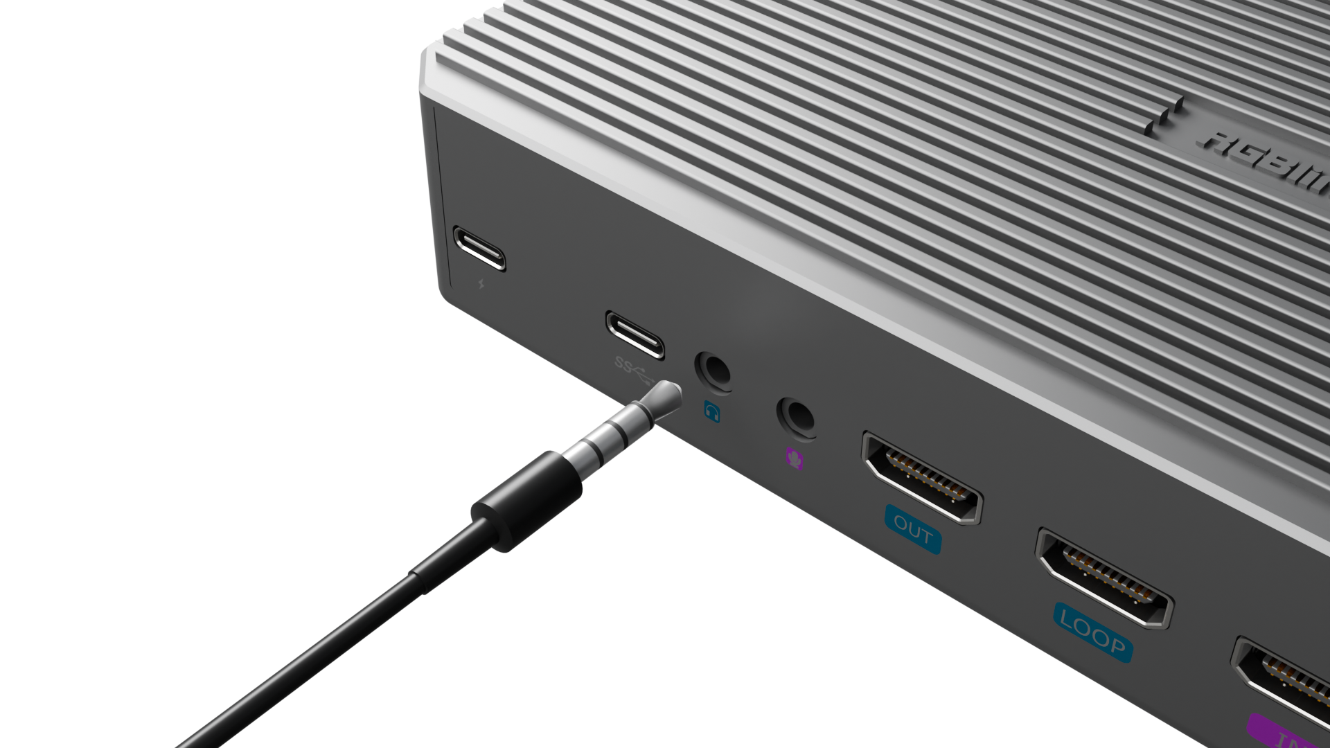
Connect Audio Cable

Connect a microphone to the Line-in interface.

Connect a speaker to the Line-out interface.

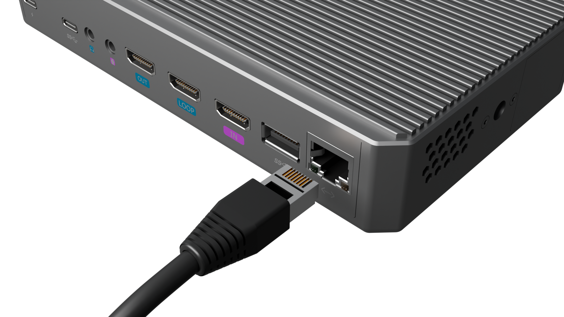
Connect Ethernet Port for Streaming

Use an Ethernet cable to connect the Gigabit Ethernet port to enable NDI encoding/decoding and network streaming.

3.1.1Logging in via Device Static IP

The device management page address of the MSP 325N V2 is its IP address.

Its factory default static IP is 192.168.5.100.

**For first-time use, **you need to set the IP of the login device (e.g., computer) to an IP in the same LAN as the MSP 325N V2's static IP, i.e., 192.168.5.x (the first three digits of the IP are the same, x is any number from 0 to 254).

Please proceed as follows:

  1. Use an Ethernet cable to connect the computer and the MSP 325N V2 (if the computer lacks an Ethernet port, use a USB to Gigabit Ethernet adapter).
  2. Disable the computer's current network to set a static IP address.
    1. Configure the computer's network settings: Go to System Settings > ** Network & Internet Settings ** > ** Network and Sharing Center** .
    2. ** Change adapter settings** > Ethernet > **Internet Protocol Version 4 (TCP/IPv4) **
    3. Select ** Use the following IP address **, enter the IP address (first three digits same as MSP 325N V2's static IP, i.e., 192.168.5.x) and subnet mask (set to 255.255.255.0).

The default gateway should also be set to 192.168.5.x. After confirming the settings, the computer and MSP 325N V2 will be on the same LAN.

  1. Open a browser, enter the MSP 325N V2's static IP (192.168.5.100). The default login username and password are both admin .
  2. After logging in, you will enter the device management page.

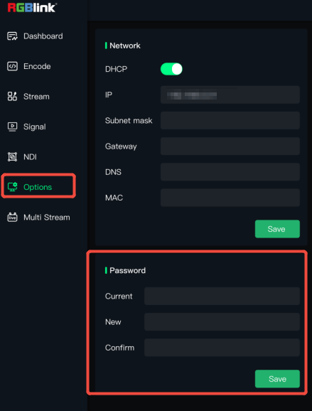
It is recommended to change the account password after the first login to ensure device management security.

3.1.2Connect the MSP 325N V2 to the Network

The MSP 325N V2's DHCP function (automatically receiving assigned IP address) is disabled by default.

After the first login using the static IP, you need to go to** Network ** in **Options ** to enable DHCP. This allows the device to obtain an IP address assigned by the router and access the network.

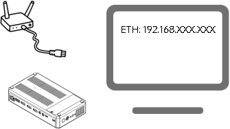
  1. Power on the MSP 325N V2 and connect it to the router using an Ethernet cable.
  2. Use an HDMI cable to connect the HDMI OUT interface on the right panel of the device to a display.

The display will show the IP address assigned to the device by the router .

The URL in the example below is for illustration only; please use the actual IP address assigned by your router).

图中网址仅为举例,请以路由器实际分配IP地址为准

3.2Dashboard

On the Dashboard, you can view:

  • Current system status of the device (CPU usage, memory usage, core temperature).
  • Current network status.
  • Connected port status.

After enabling the recording function and multi-platform live streaming function:

  • REC will display the current recording duration.
  • ON AIR will display the current live streaming duration.


After the MSP 325N V2 connects to a signal or input stream address, if **Preview **is enabled, you can preview the connected signal on the Dashboard.

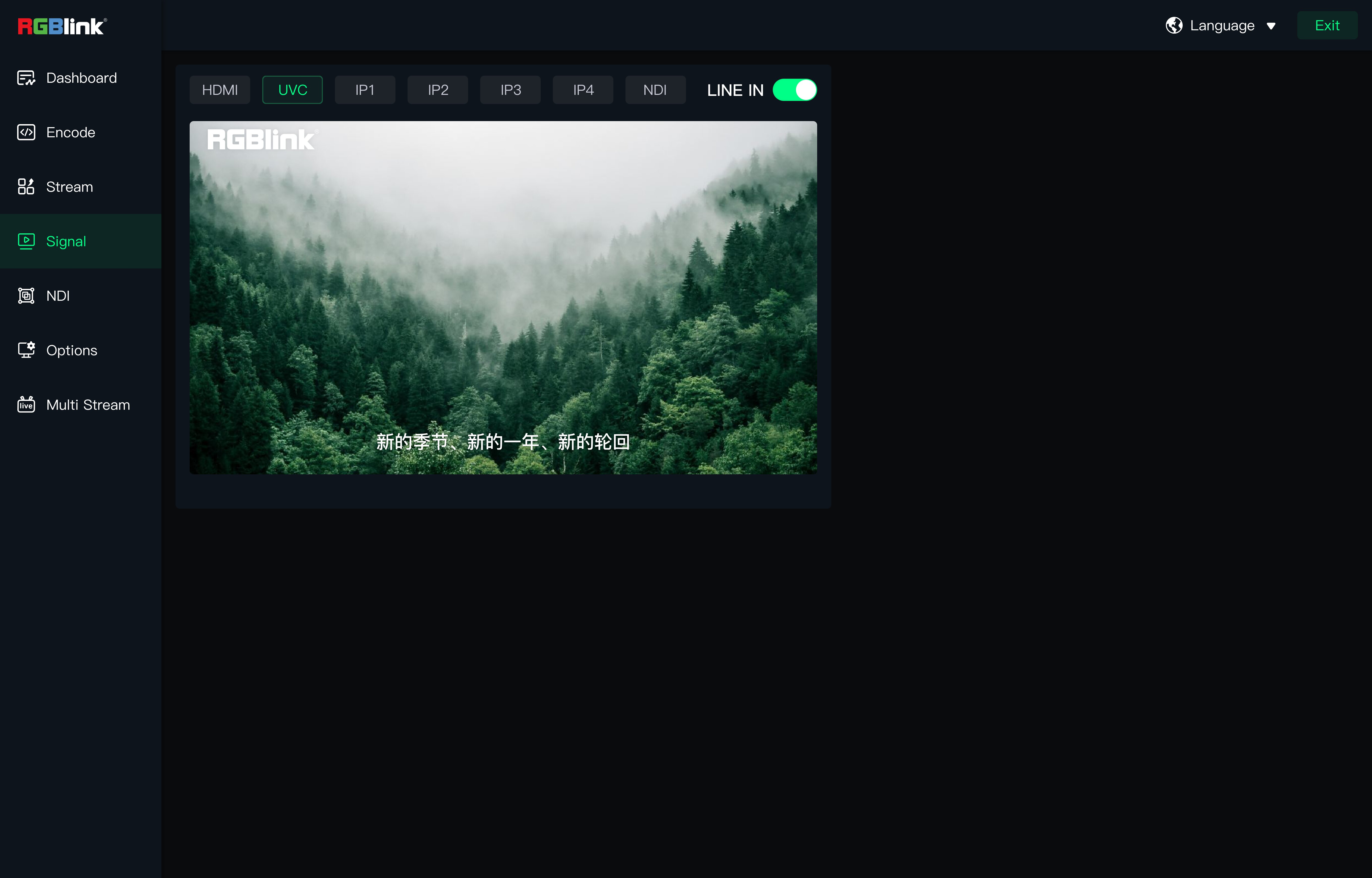
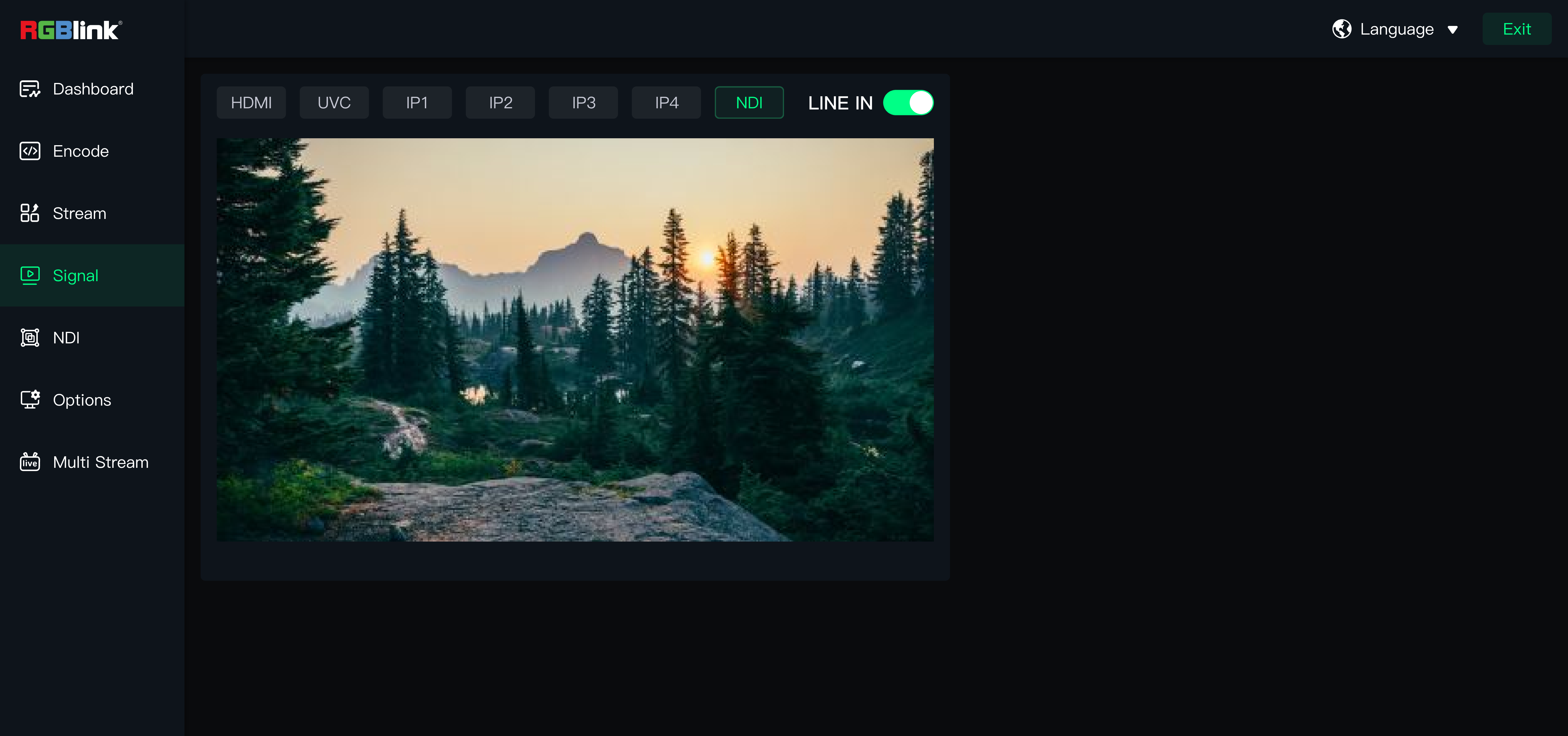
3.3Signal Switching

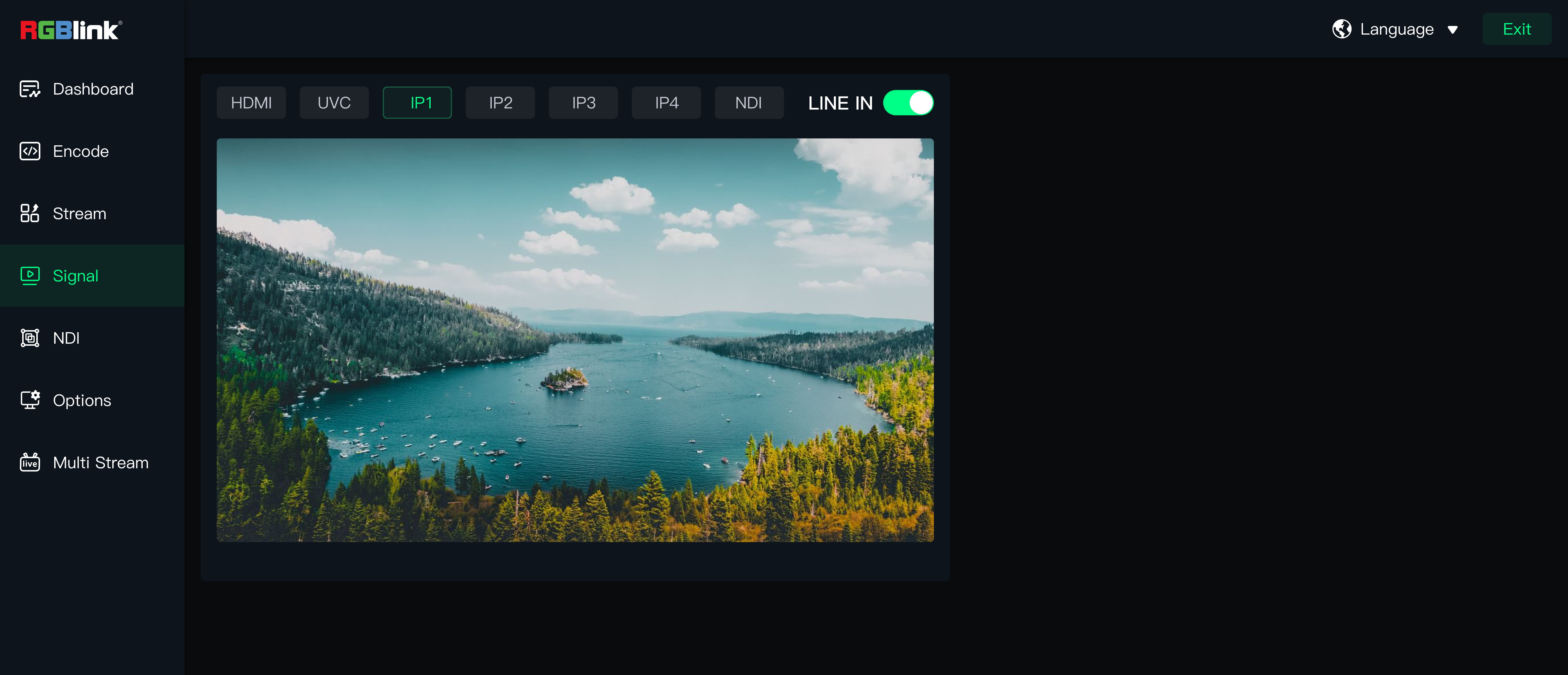
On this page, you can preview all signal sources connected to the MSP 325N V2 via physical interfaces and network inputs.

Click on which signal, that signal will appear in the preview window and on the main output display device connected to the HDMI OUT port.

3.4Encoding Settings

Encoding settings involve the configuration of compression parameters for video and audio, including resolution, codec format, bitrate control method (such as CBR or AVBR), frame rate, GOP and more.

These settings are designed to reduce file size or transmission bandwidth while maintaining perceptual quality, making them suitable for both local storage and streaming applications.

On this page, you can globally configure parameters for the Main Stream, Sub Stream video, and audio.

3.4.1Main/Sub Stream Video Parameters

Main/Sub Stream parameters are typically used for video conferencing or RTMP live streaming.

  • The Main Stream is used for high-quality, high-definition main picture transmission and is the core content for viewing.
  • The Sub Stream is usually for screen sharing (PPT, documents, etc.) or abackup relatively low-resolution stream switched to when the network is poor.

Resolution

The resolution can be set up to 4K@60Hz.

Encoding Method

  • H.264 (AVC): Video encoding standard, balances compression rate and picture quality, good compatibility, suitable for live streaming, video conferencing, etc.
  • H.265 (HEVC): An upgrade to H.264, improves compression efficiency by about 50% (lower bitrate at the same quality) but requires stronger hardware support. Suitable for 4K/8K ultra-high-definition video.
📢  **Notes**

Baseline/Main/High encoding cofigurations sequentially provide higher picture quality but requiring slightly higher computational demands.

Bitrate Control

ModeNamePicture QualityApplicable Scenarios
CBRConstant BitrateFluctuates greatly, unstableNetwork live streaming, video conferencing
VBRVariable BitrateHigh and stableLocal recording, movie encoding
AVBRAdaptive Variable BitrateVery high and more stableLive streaming requiring both quality and network stability
FIXQPFixed Quantization ParameterConstantVideo quality testing, extreme quality recording

GOP (Group of Pictures)

The interval duration between two keyframes, in seconds. Affects video error tolerance and compression efficiency.

3.4.2Audio Parameters

The audio can be set to AAC (Advanced Audio Coding) format, with a maximum sample rate of 48Kbps, supporting stereo dual channels.

The bitrate can be set to 128Kbps to ensure audio quality details.

3.4.3Local and Group

After completing the configuration, you can choose ** Apply to Local** , meaning the settings only apply to this MSP 325N V2 unit.

Or choose** Apply to Group** , meaning the settings will be saved to all discoverable MSP 325N V2 units on the local area network (connected to the same network as you).

  • Click Apply to Group the system will automatically search and display MSP 325N V2 units on your same LAN.
  • Click** Start Sync ** to synchronize the encoding settings to these devices.

3.4.4Network Input

The MSP 325N V2 also supports network input as a signal source, supporting HTTP/SRT/RTMP/RTSP/NDI streaming protocols.

Enter the corresponding stream address to obtain the picture.

This page uses pulling the picture from an IP-enabled PTZ camera into the signal monitoring picture as an example.

📢  **Important**

The IP address of the device must be on the same network segment as the camera's IP address, meaning the first three digits of the device's IP address are the same as the first three digits of the PTZ camera's IP address.

Using Static IP

Case 1: One PTZ and one MSP 325N V2
  1. In this case, you can make the MSP 325N V2 match the PTZ's IP. Connect the PTZ and MSP 325N V2 with an Ethernet cable.
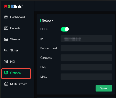
  2. After obtaining the PTZ's IP address from its manual or control panel, go to Options on the MSP 325N V2, disable DHCP.

Manually configure the MSP 325N V2's IP address, setting the first three digits of the MSP 325N V2's IP to be the same as the PTZ's IP. Click Save after setup.
Case 2: Four PTZs and one MSP 325N V2
  1. Plan a unified network segment, such as 192.168.1.x with subnet mask 255.255.255.0.
  2. Disable DHCP on the MSP 325N V2 and assign it a static IP (e.g., 192.168.1.x, where x is 1–254). Save the settings and refresh the page.
  3. Power on the four PTZ cameras and assign each a static IP within the same range (192.168.1.x).
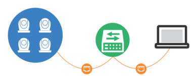
  4. Connect the MSP 325N V2 and all PTZ cameras (all with static IPs) to the same switch via Ethernet cables.
  5. Also connect your computer to the same switch. Press Win + R, type cmd, and press Enter. Ping each device's IP address one by one—a successful reply confirms the device is reachable.
For Automatic/DHCP Setup

  1. Ensure both the PTZ cameras and the MSP 325N V2 are set to obtain IP addresses automatically (via DHCP).
  2. Connect all devices—including the MSP 325N V2, PTZ cameras, and your computer—to the same switch.

The router will assign IP addresses to all devices, keeping them on the same network segment.

📢  **Note**

The MSP 325N V2 supports PoE power supply. If the chosen PTZ camera also supports PoE, it is recommended to use a PoE switch. In this case, neither the MSP 325N V2 nor the PTZ requires a power adapter, simplifying wiring.

Add Stream Addresses in MSP 325N V2

If you confirm that the MSP 325N V2 and the PTZ camera are on the same LAN, this device supports accessing the PTZ camera's (pan-tilt-zoom camera) picture via standard network protocols.

To connect successfully, you need to provide the camera's streaming address.
Most stream addresses follow this general structure; you only need to replace the variables.

The IP address is the static IP you set for the PTZ when connecting it to the same network as the device, or the dynamic IP obtained from the router.

The username, password, and stream path need to be checked in the PTZ's manual.
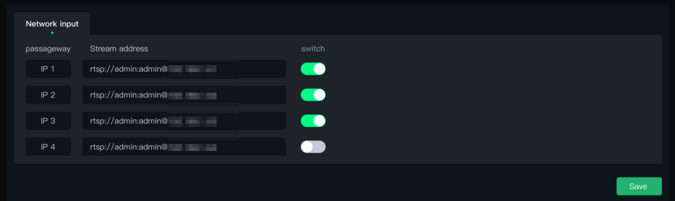
Enter a description for the stream address, then click Save below to save the settings. Now you can enable this stream address and view the PTZ signal in the preview column on the Dashboard.
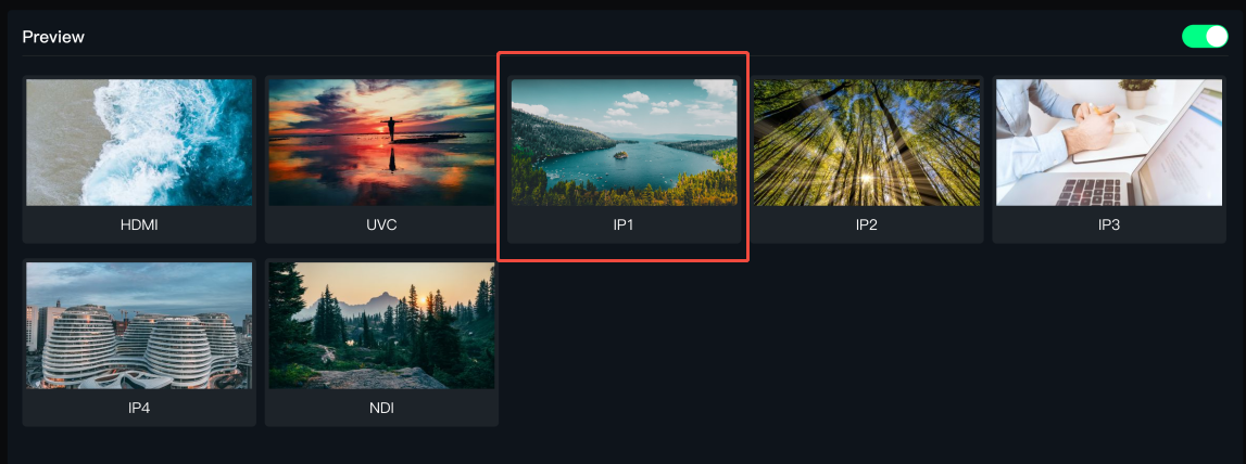
On the **Signal **page, select a IP signal for HDMI output display.

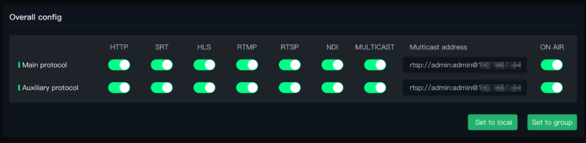
3.5.1Global Configuration

In** Global Configuration**, you can choose the streaming protocol for the Main Stream or Sub Stream as HTTP/SRT/HLS/RTMP/RTSP/NDI/Multicast protocol.

  • Select** Apply to Local **to save the settings to this machine.
  • Select** Apply to Group **to synchronize the settings to other MSP 325N V2 devices found on the LAN.

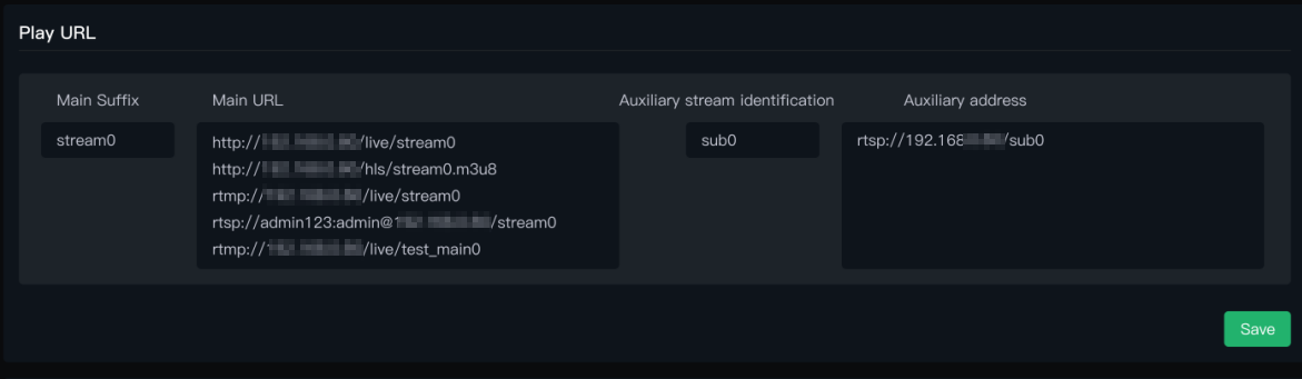
3.5.2Playback Address

  1. The Main Stream and Sub Stream code identifiers can be modified; however, the supported playback formats of the Main Stream and Sub Stream addresses are fixed and cannot be changed.

The Main Stream supports playback in multiple formats including HTTP, RTMP, RTSP, and SRT. You can select the appropriate Main Stream URL format based on compatibility with your player, platform, or network requirements — all formats provide access to the same Main Stream video output.

The Sub Stream, however, only supports RTSP format.

  1. For the different protocols in the Main and Sub Stream address formats, a simple summary is as follows:
ProtocolFeaturesScenarios
RTMPVery low delay (usually 1-3 seconds), very stable.Streaming to live platforms (Douyu, Twitch, etc.), professional live production.
RTSPDesigned for streaming control (e.g., play, pause). Needs specialized players (like VLC).Surveillance cameras, video conferencing systems, embedded devices.
HTTPHTTP-based. Can cut the stream into small files for download and playback.Web live streaming (Bilibili, YouTube).
SRTTargets unstable network environments, low latency.Remote production, high-quality low-latency transmission across public networks.
  1. VLC software supports playing all the Main Stream address formats above. You can consider downloading VLC Media Player (https://soft.ljdwl.cn/vlc/bFqbx37.html).
    1. Open VLC Player, click Media on the top menu bar. In the dropdown menu, select Open Network Stream....
    2. An input box will pop up. Copy and paste the complete address you see into it, then click Play .

3.5.3Recording

The MSP 325N V2 supports recording the Main Output picture after inserting a USB drive or solid-state drive into the USB-A interface of the MSP 325N V2.

  • The maximum supported capacity for USB drives is 128GB, for SSDs it is 2TB.
  • The supported format is exFAT.
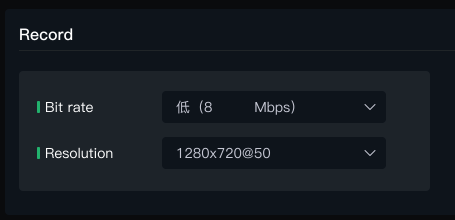
  1. Set the recording bitrate and resolution.
    1. Low quality recording bitrate is 4Mbps; Medium quality recording bitrate is 8Mbps; High quality recording bitrate is 16Mbps.
    2. Supports up to 4K resolution.

  1. Insert the USB drive. On the Recording interface, the MSP 325N V2 will automatically read the used capacity and free capacity of the USB drive. Click the recording switch, and the MSP 325N V2 will start recording and display the total recording duration and recording progress.
  2. During recording, you can view the recording dynamics and time on the Operation Status page.
  3. After turning off the recording button, the recording content is automatically saved, and the inserted USB drive or portable hard drive is automatically ejected from the device.
  4. Insert the USB drive or portable hard drive into a computer to view the recording files. The file format is MP4.
📢  **Note**

- The supported format for USB drives is exFAT. If the drive is not formatted correctly, please reformat it: On a Windows computer, select "exFAT" as the file system and set the allocation unit size to 128KB.
- Video recordings are automatically segmented into 4GB files. Recording will stop automatically when the disk is full. To avoid interruptions, regularly check the remaining space of the USB drive in the recording menu.

3.5.4Volume Adjustment

You can adjust the volume of the Main Output picture here, or enable "Mute" to mute the Main Output.

3.6.1NDI Encoding Settings

The NDI encoding function converts the signal from a USB camera into an NDI stream via the network port.

Specific steps are as follows:

  1. Connect the USB camera to the MSP 325N V2.
  2. Configure the computer and MSP 325N V2 to be on the same LAN.
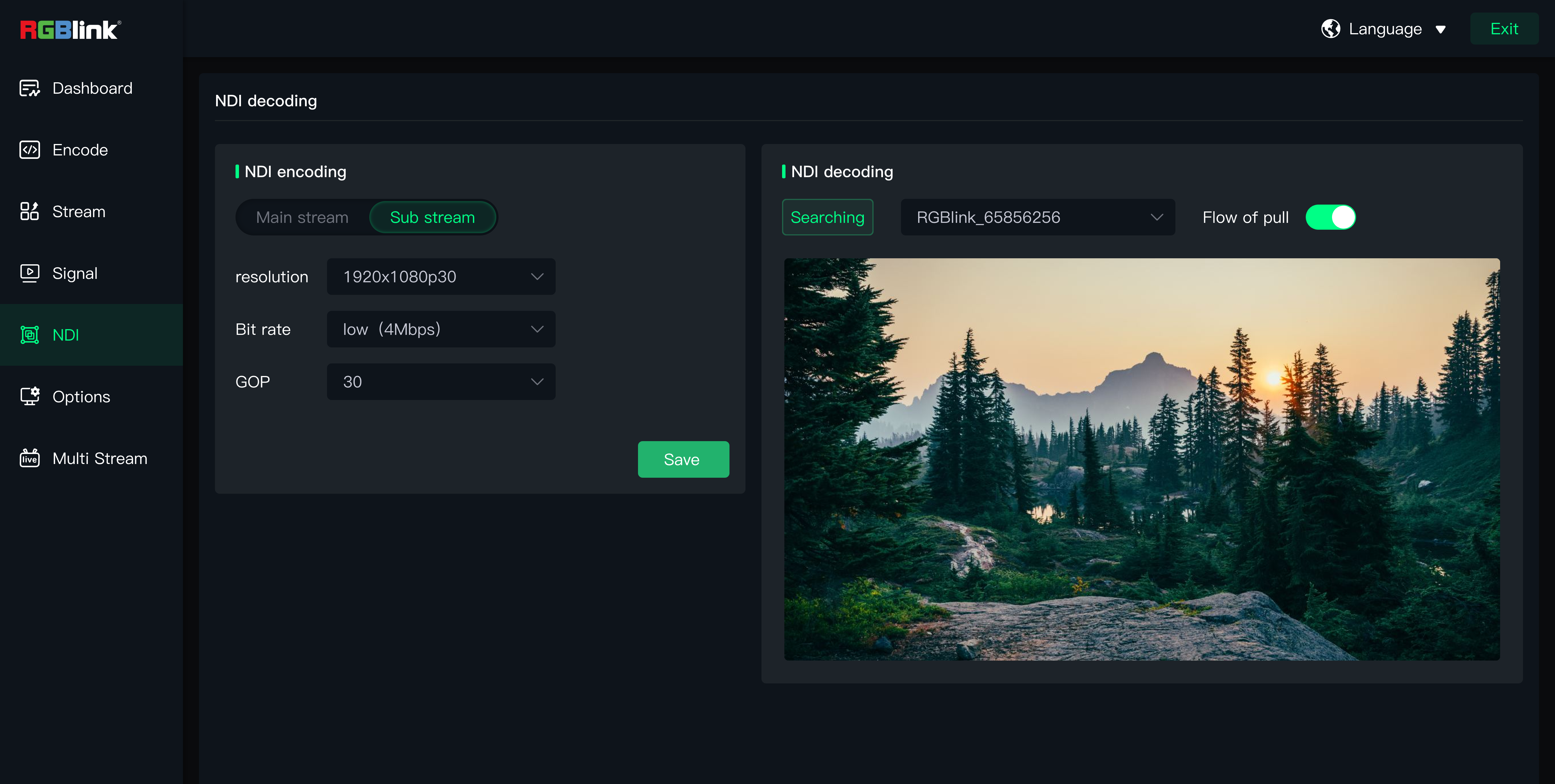
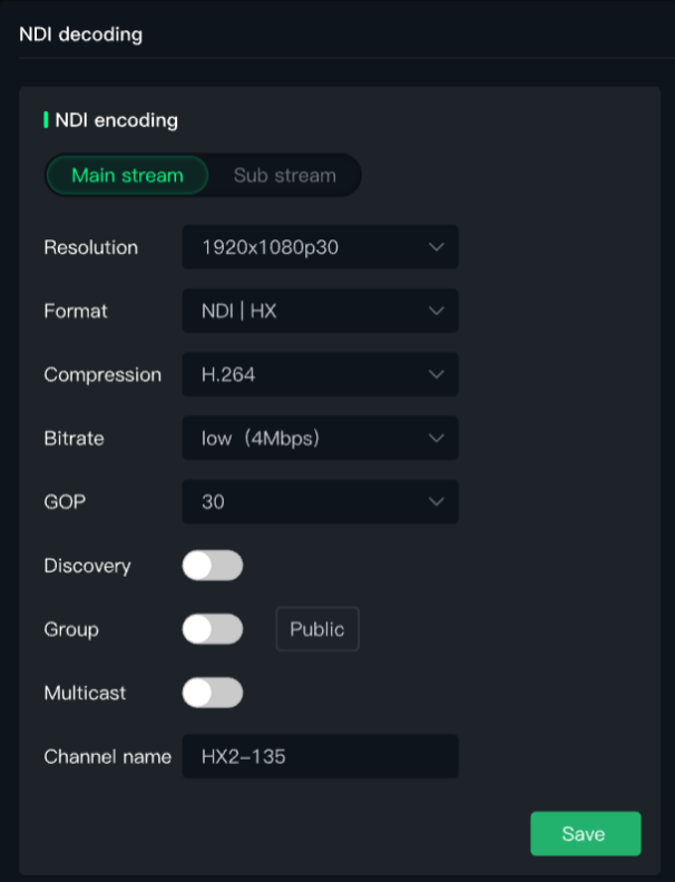
  3. Set the NDI encoding format. Set the NDI resolution, format, compression format, bitrate, etc., and click** Save** .

1. Resolution: Displays the resolution of the input signal source. Maximum resolution supported is 3840x2160p@60Hz.
2. Format: NDI encoding formats support Full NDI, NDI | HX3, NDI | HX2, NDI | HX.
3. Compression Format: Default is H.264.
4. Bitrate: Supports up to 8Mbps.
5. Channel Name: Not editable. If the channel name displays as HX-100, where HX is the format selected for NDI encoding, and 100 is the last field of the IP. Users can make overall modifications through the host software.
6. GOP: The interval between key frames. Larger settings save bandwidth but slow down scene switching and fault recovery. If the GOP length is 60 frames and the video frame rate is 30fps, it means there is a key frame every 2 seconds (60 frames / 30 frames/sec = 2 seconds).
7. Group: All NDI signals are in the public group by default if not grouped. You can enable  **Group** for grouping.
8. Multicast: The encoder only sends one data stream to the network.
9. Discovery: Enabling this switch allows other devices on the network to automatically find your encoder without manually entering the IP address.

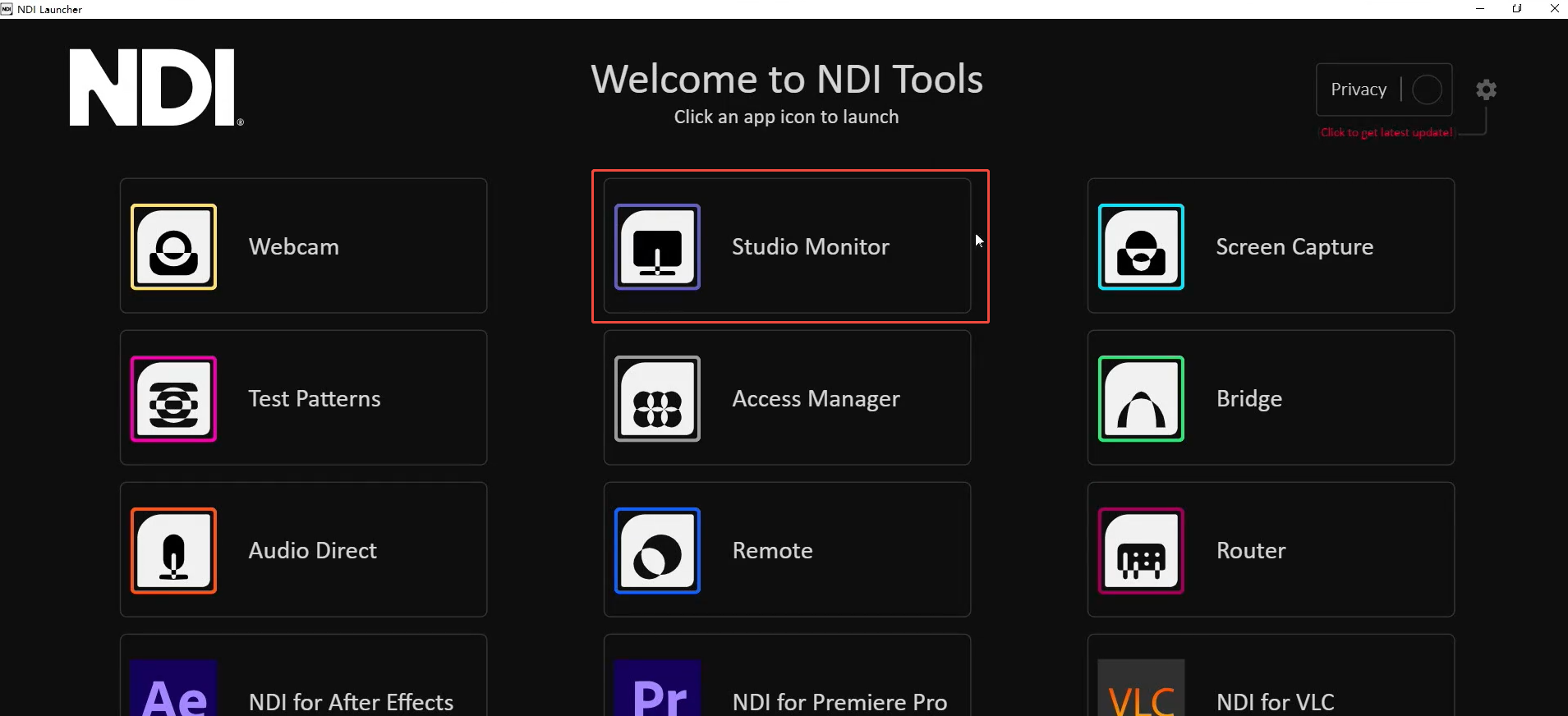
3.6.2Using NDI Tools to Output NDI Source

  1. Download URL:https://www.newtek.com/ndi/tools/
  2. Open NewTek's Studio Monitor software.
  3. Click the icon in the upper left corner to display the list of device names discovered by the Monitor software. Directly select the device you need to connect to, and it will pull and play the currently selected video stream. After successfully pulling the video stream, you can click on the blank area of the device to view the NDI resolution.

3.7NDI Decoding

  1. Connect the switch and router with an Ethernet cable, then connect the MSP 325N V2, NDI camera, and computer to the switch, placing them on the LAN.
  2. On the NDI Enc1. Connect the switch and router with an Ethernet cable, then connect the MSP 325N V2, NDI camera, and computer to the switch, placing them on the LAN.
  3. On the NDI Encoding/Decoding page, under NDI Decoding, click Search for NDI Source. Then click Pull Stream, and the NDI source picture will appear in the preview window.
  4. The decoded NDI video now becomes an input source. You can switch the HDMI output signal on the **Signal **page.oding/Decoding page, under NDI Decoding, click Search for NDI Source. Then click Pull Stream, and the NDI source picture will appear in the preview window.
  5. The decoded NDI video now becomes an input source. You can switch the HDMI output signal on the "Signal" page.

3.8Options

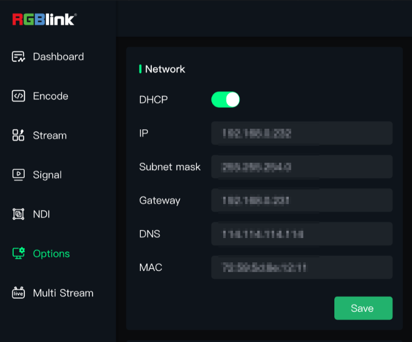
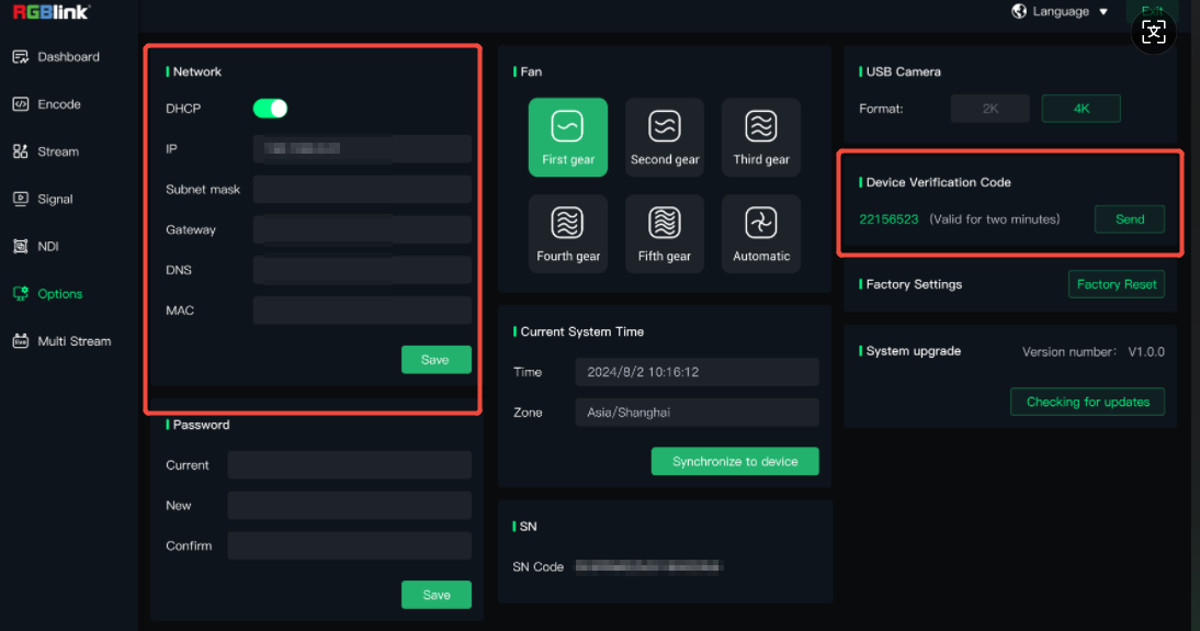
Network Port

When the MSP 325N V2 leaves the factory, the DHCP function (automatically receiving assigned address) is disabled by default.

After the first login using the static IP, you need to go to **Network Port in Options **to enable DHCP. Disabling DHCP allows manual IP address setting.

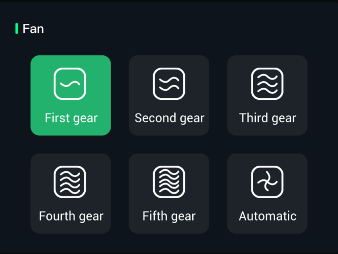
Fan

Click Fan Speed Adjustment to control the speed of the built-in fan of the MSP 325N V2, enhancing heat dissipation performance.

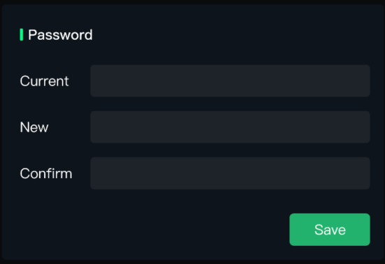
Change Password

After the first login, for the security of your account, it is recommended to change the password immediately.

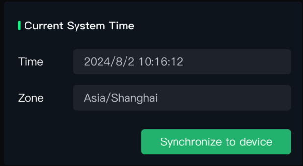
Time Setting

After connecting to the network, the device will automatically synchronize with the local network time, which cannot be modified. You can choose to synchronize to the device.

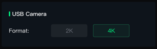
USB Camera

Here you can set the output resolution of the connected USB camera to 2K or 4K.

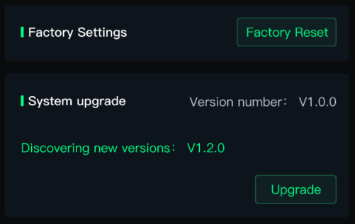
Factory Reset and Upgrade

Restoring factory settings will unbind the device and reset all user configurations. This operation is irreversible. **Please back up important data before performing it! **

The MSP 325N V2 supports online upgrades. When connected to the network, click** Upgrade **to detect the latest version and upgrade online.

3.9.1Binding to TAO Cloud Platform

  1. Follow the steps in 3.1.2 Connect the MSP 325N V2 to the Networkto the Network to ensure the MSP 325N V2 is connected to the network. When connected, the IP from your router and the 8-digit device verification code for binding TAO Cloud are shown in the** Options** page.
  2. Register and log in to TAO Cloud (TAO Cloud address: https://www.tao1live.cn).
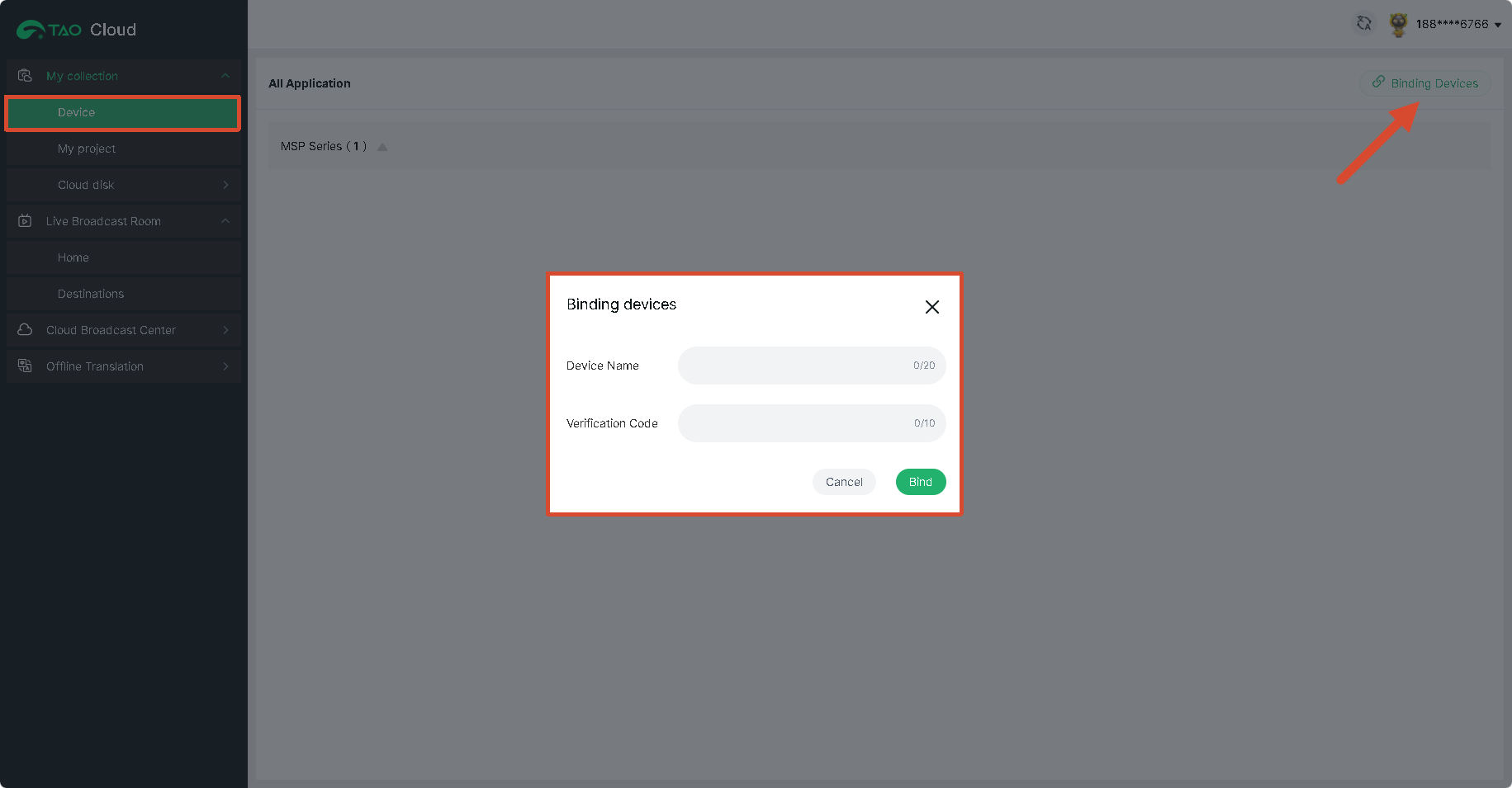
  3. Click** My Collection** > Device > ** Binding Devices** . If binding fails, return to the MSP 325N V2 management page > Options, refresh the Device Verification Code , and try binding again.
  4. After successful binding, the MSP 325N V2 will appear in the list of bound devices.
  5. If you want to bind another TAO Cloud account, retrieve the verification code again and use it to bind the other account.

3.9.2Streaming on Device

In above operations, MSP 325N V2 has been connected to the network. Then TAO cloud can assign a streaming address.

🚨 ** Risk Warning**

**Do not share your stream key with anyone or display it during a live stream.** Doing so may result in unauthorized account access, stream hijacking, or other potential risks and losses.

If your stream key is exposed:

1.  Immediately reset the stream key on the corresponding platform.
2.  Stop the current live stream.
3.  Restart streaming using the new stream key.

How to Get Your Stream Key (Guide for major platforms)

PlatformIntroductionOfficial Guides
YouTubeGo to YouTube Studio. Click** Create > Go live**. Copy the Stream key and Stream URL from the stream settings tab.https://support.google.com/youtube/answer/9854503?hl=en#zippy=%2Cadd-a-trailer-to-your-live-stream%2Cstream-key%2Cstream-url
FacebookFrom Feed/Page/Profile, click Live video (Enter Live Producer). Click** Go live > Select > Streaming software**, then find and copy Stream Key/ Server URL.https://www.facebook.com/business/help/165076674943644?id=1123223941353904
TwitchOpen profile icon > Creator Dashboard > Settings > Stream and copy the Primary Stream Key.https://help.twitch.tv/s/article/twitch-stream-key-faq?language=en_US
Bigo LiveGo to **profile avatar > Personal Center > Settings menu > Enable "OBS Streaming" option **. Copy provided Server URL and Stream Key.https://www.bigo.tv/blog
.........
Platforms-Specific Notes
Some platforms, including TikTok and Kwai, restrict direct RTMP access and require proprietary software.

To stream the content to a platform

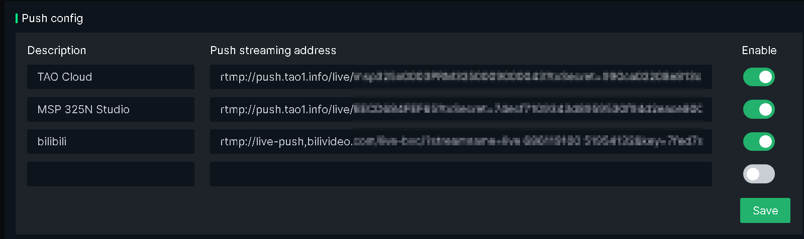
  • Open TAO Cloud, connect it to the MSP 325N V2 device, fill in the copied Stream URL/Stream key into the Push Stream Address Box , click **Send **, and the MSP 325N V2 device will automatically recognize the push stream address.
  • After the live streaming, the **ON AIR **box in the main interface will have a red border.
  • Copy the live platform's streaming address and stream key into the streaming address field of the MSP 325N V2. After saving, click Enable, and the device will automatically recognize the streaming address."

3.9.3Monitoring Live Streams on TAO Cloud

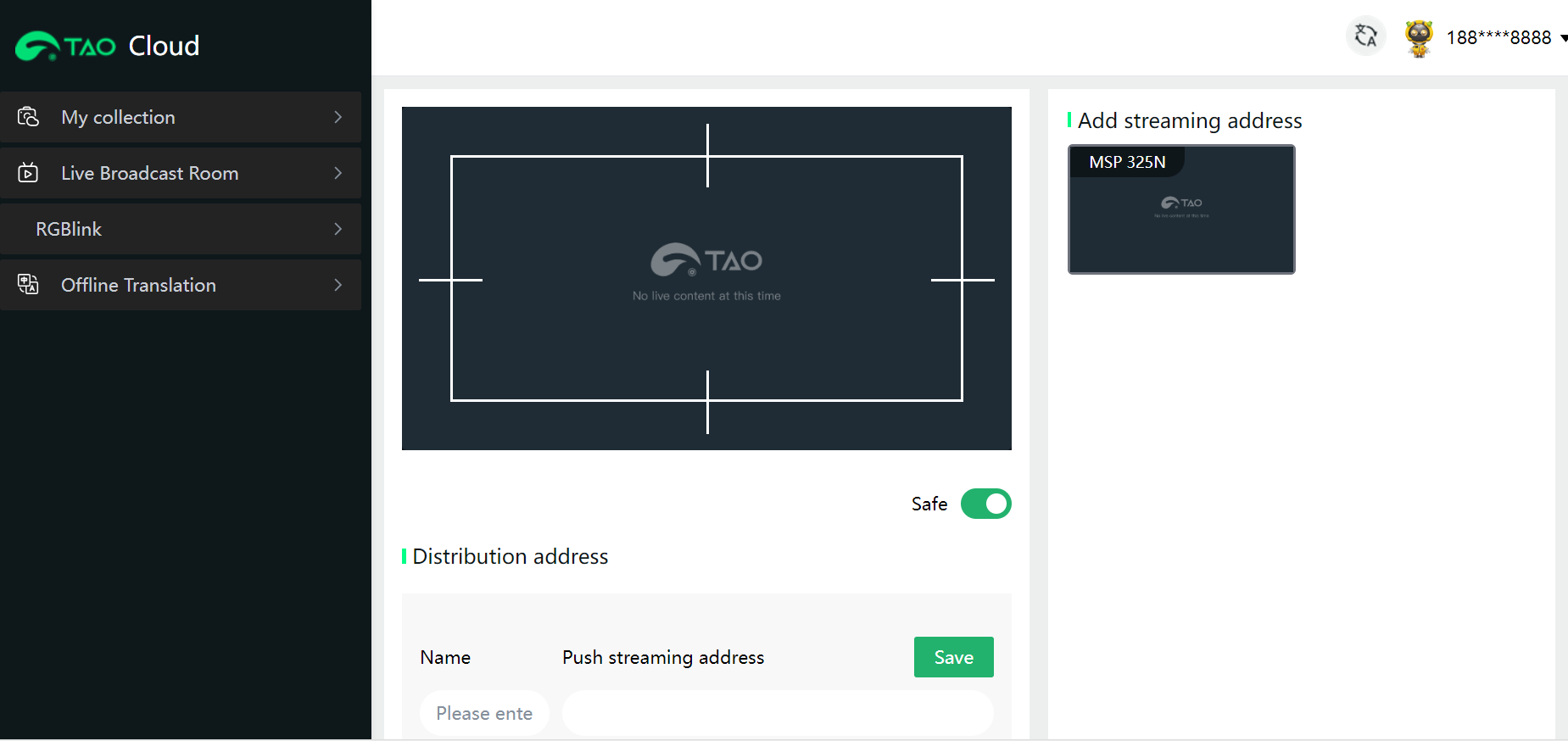
The first streaming address of the MSP 325N V2 is used for streaming to TAO Cloud to monitor the live stream画面 (picture). It is unmodifiable by default and can only be enabled after obtaining TAO Cloud membership.

  1. Become a TAO Cloud Member
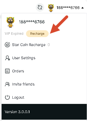
    1. Click Enable to the right of the TAO Cloud address. Then click Buy Now to jump to TAO Cloud. Click the avatar then select Recharge to purchase membership.

2. Select the subscription package you want to purchase, click on the payment method, jump to the payment platform to complete the payment, and you will become a TAO Cloud member.![](https://rgblinkw3media9490.blob.core.windows.net/product-images/online-document-images/msp-325n-v2-manual-import/yuque-1777546807879-00e3a02a.png)

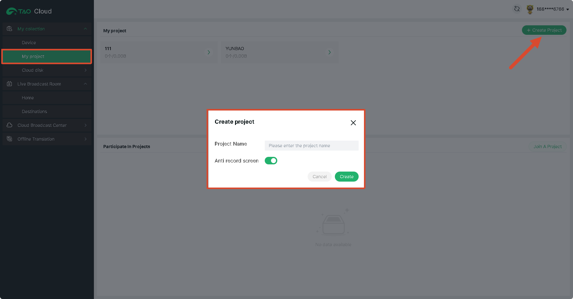
2. After becoming a TAO Cloud member, refresh the **Multi-Platform Live Streaming **page of the MSP 325N V2. Enter a description for the address as needed, click Save, and finally click Enable. 3. Ensure the MSP 325N V2 is already "bound to the TAO Cloud platform". In the navigation bar, select My Collection > Project, and create a project. This project can be used to pull streams and view all live rooms after bound TAO Cloud devices start streaming. When you create a project, the video anti-screen recording function is enabled by default. If you need screen recording, you can manually disable it. 4. Enter the created project and click Add Bound Device to add the MSP 325N V2 to the project. At this point, if you directly click on the MSP 325N V2 in the device management bar, you will go directly to the device management page. 5. To view the picture streamed to TAO Cloud, click to enter the Cloud Live Room in the cloud director section below. Here you can view the live stream picture of the MSP 325N V2.

3.9.4Using VLC to Monitor Live Streams

You can also choose other software like VLC Media Player or PotPlayer to view the live content. Download VLC software (https://soft.ljdwl.cn/vlc/bFqbx37.html) and open it:

  1. Check the MAC address (Media Access Control address) in **Network Port **under Options on the MSP 325N V2.
    Example: 809d65020e28 (remove the colons between characters).
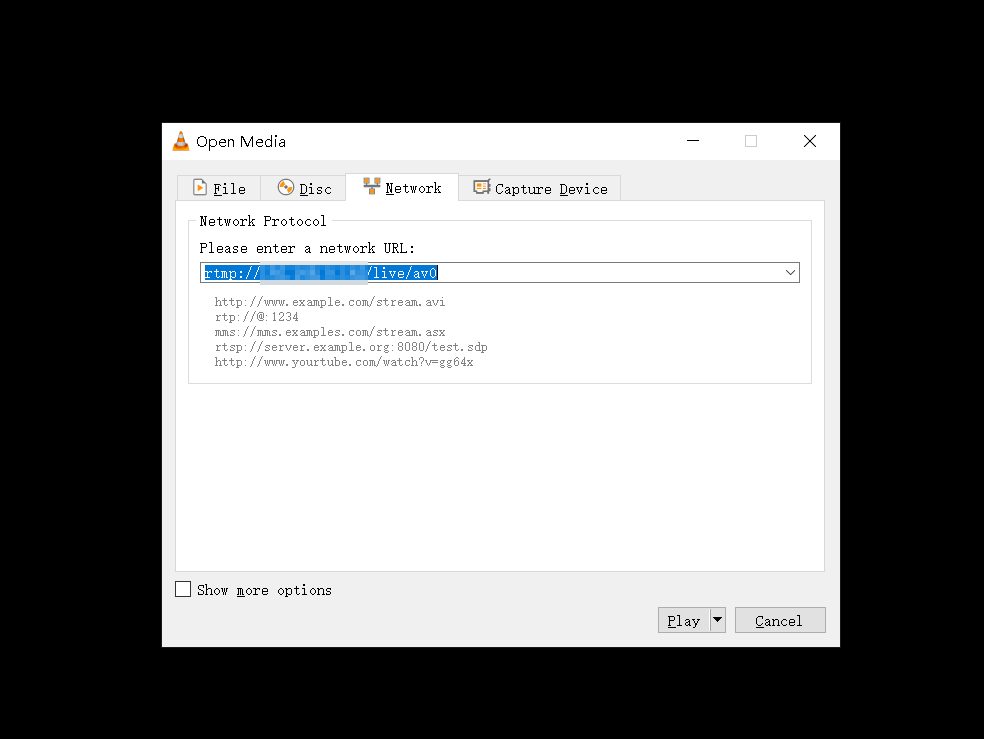
  2. Open VLC Media Player, click **Media ** > Open Network Stream , then enter the network URL and click "Play" to view. The network URL input format is:
    https://play.tao1.info/809d65020e28.flv
    The website format remains unchanged; enter the MAC code provided by your network in the middle.

3.9.5Using TAO Cloud for Multi-Platform Streaming

Becoming a TAO Cloud member also breaks through the quantity limit of local multi-platform streaming, allowing streaming to 30+ mainstream platforms globally.

  1. Create a Cloud Live Room on TAO Cloud
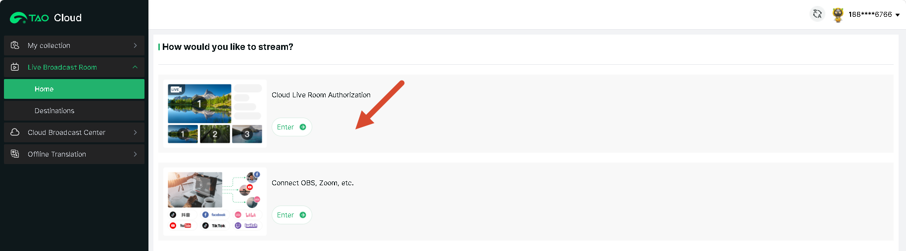
    1. Log in to TAO Cloud (same account as TAO App registration). In the navigation bar, select Live Broadcast Room > Cloud Live Room Authorization.
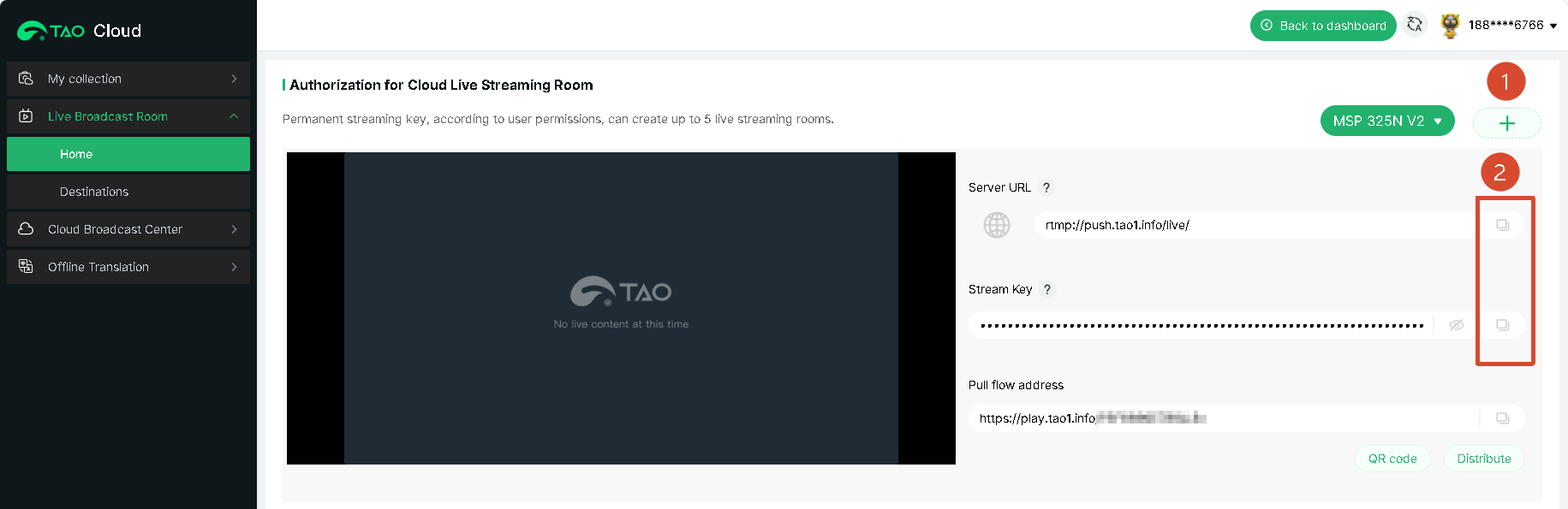
    2. Click the + sign to create a live room. Copy the server address and stream key to the streaming address field. The format for copying the TAO Cloud streaming address to the MSP 325N V2 is: server address directly followed by the stream key.

    3. Click Save, then click Enable for this streaming address.
    4. The video preview window will now display the picture from the TAO Cloud live room.

  2. Set Up Live Rooms on the TAO Cloud Platform
After enabling the TAO Cloud platform's live room address, to use this address to stream to multiple live streaming platforms, you need to set up the live room information for different platforms on TAO Cloud.

The operation is as follows:

1. In the TAO Cloud navigation bar, select **Live Broadcast Room**, enter Connect OBS, Zoom, etc..![](https://rgblinkw3media9490.blob.core.windows.net/product-images/online-document-images/msp-325n-v2-manual-import/yuque-1777546809652-4a24f0b1.png)
2. TAO Cloud comes pre-equipped with mainstream streaming platforms at home and abroad. Directly click on the platform you want to stream to and complete the information setup. Or click Other to add a new platform. ![](https://rgblinkw3media9490.blob.core.windows.net/product-images/online-document-images/msp-325n-v2-manual-import/yuque-1777546809845-86bccf96.png)
3. Distribution bar: Click the** +** sign to add the already set up distribution platforms. After successful addition, you can click the icons individually to start streaming, or turn on All Platforms Online to achieve multi-platform streaming with one click.![](https://rgblinkw3media9490.blob.core.windows.net/product-images/online-document-images/msp-325n-v2-manual-import/yuque-1777546809863-6f0e742c.png)
4. After achieving multi-platform streaming, if you want to modify the live room information, you can do so on the TAO Cloud Video Matrix management page.![](https://rgblinkw3media9490.blob.core.windows.net/product-images/online-document-images/msp-325n-v2-manual-import/yuque-1777546809795-d2a62689.png)

About Us / Find Support

Xiamen RGBlink Science & Technology Co., Ltd. designs and manufactures professional video processing, switching, streaming and LED display control products for live events, broadcast, education and fixed installations.

Need help?

Choose one of the following support options:

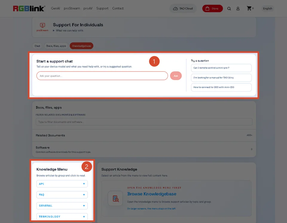
  • AI Support Search (Recommended): Visit Support > Support proStream/proAV/proEvents on the RGBlink official website and ask the RGBlink AI Bot for quick answers.
  • FAQs: Visit Support > Support proStream/proAV/proEvents on the RGBlink official website and browse Knowledge Menu > FAQ.
  • Contact Technical Support: Visit the Technical Support page of this manual or the RGBlink official website for our contact details.

Document image

RGBlink

www.rgblink.com

© Copyright Xiamen RGBlink Science & Technology Co Ltd