Online Manual
Q16pro-Gen2-4U

3.2.2 XPOSE 2.0_Operation
Launching XPOSE
After installation, double-click the XPOSE 2.0 icon to launch the software.
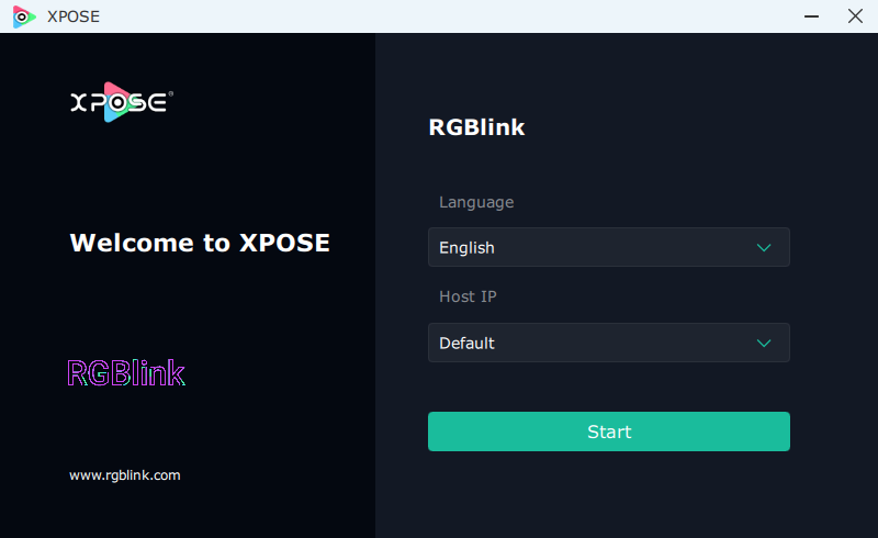
When launching XPOSE for the first time, select the desired language and the local IP address, then click Start.
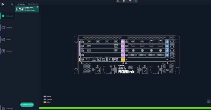
If a device is connected successfully, the main workspace displays the rear panel of the device.
Workspace Overview
The XPOSE 2.0 workspace includes the following functional areas:
- Workspace
- System Settings
- Properties
- Device Connection
- Input/Output Configuration
- Display Management
- Layer Configuration
- Scene Management
The toolbar at the top of the workspace provides quick access to the following functions:
- Synchronize Device
- Lock Workspace
- Center Rear Panel
- Power On/Off
Use the mouse wheel to zoom in or out of the workspace.

System Settings
Click the ⚙ Settings icon in the lower-left corner to open the System Settings page.
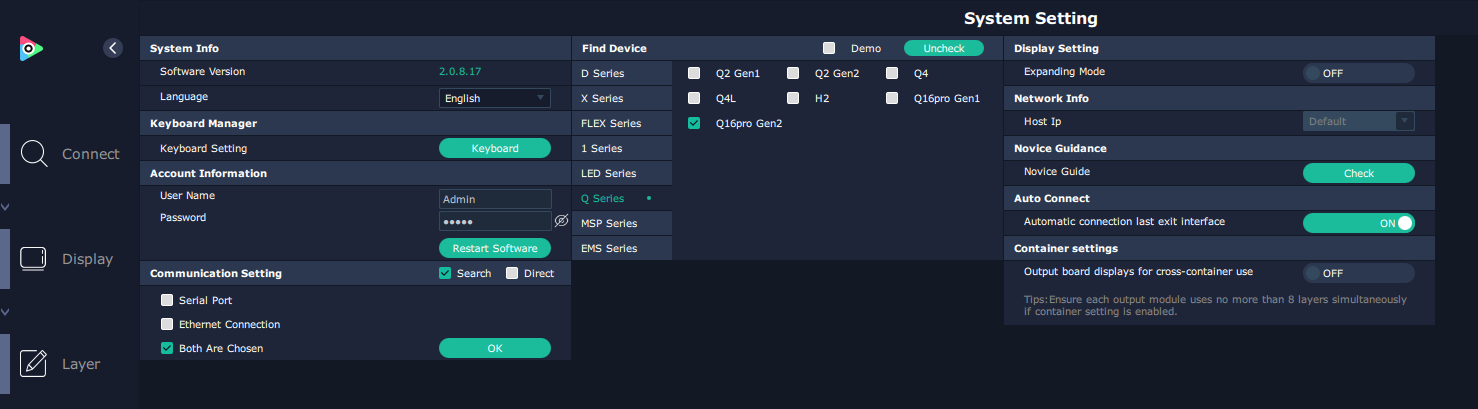
The following settings are available.
System Info
Displays the current software version and language.
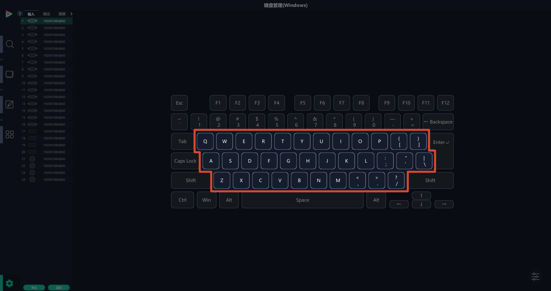
Keyboard Manager
Configure keyboard shortcuts for inputs, outputs, layers, and scenes.
Drag frequently used functions onto the corresponding keys. Shortcut configurations can also be exported or imported.
Account Information
Displays the current username and password.
You can also restart XPOSE from this page.
Communication Settings
Select the communication method used to connect the device.
Supported options include:
- Serial Port
- Ethernet Connection
- Both are Chosen
Click OK to apply the changes.
Find Device
Select the product series and device model used for device discovery.
Display Settings
Configure the extended display mode.
Network Info
Displays the Host IP address.
Novice Guidance
Checks the XPOSE operation guide.
Auto Connect
When enabled, XPOSE automatically restores the previous workspace the next time the software starts.
Container Settings
Allows displays connected to the same output card to be shared across different containers.
User Management
Properties
Click the properties icon in the lower-right corner (as shown in the red circle) of the main workspace to open the device properties.
The properties page provides access to device Overview, IP, Fan Control, Backup, and Factory Setting and so on.

Overview
| Item | Illustration | Description |
|---|---|---|
| Device Info | 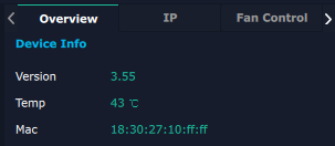 | The Device Info page displays the communication board version, device temperature, and MAC address. |
| Input Module Info | 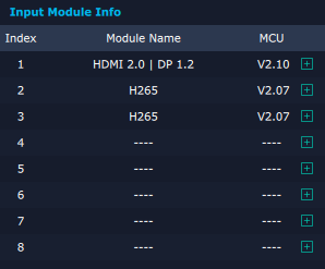 | The Input Module Info page displays the installed input module name and MCU version. If no input module is installed, .... is displayed. |
| Output Module Info | 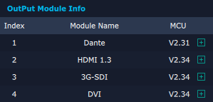 | The Output Module Info page displays the installed output module name and MCU version. |
IP
The IP page supports automatic and manual IP configuration.
In automatic mode, the device obtains the IP Address, Netmask, and Gateway automatically.
In manual mode, enter these parameters manually.

Fan Control
The Fan Control page supports automatic and manual fan speed control.
Set Fan Speed to 0-100 in manual mode.

📢  Notes

Set the manual fan speed to 30 or higher to ensure sufficient heat dissipation.
Backup
The Backup page provides input and preset backup modes.
Set Backup to ON or OFF to enable or disable the backup function.
Set Backup Mode to Input Backup or Preset Backup. Click Add to add a backup source.

Factory Setting
The Factory Setting page provides options for clearing EDID parameters and retaining network settings after a reset.
- Remove EDID: Clear the saved EDID parameters.
- Save IP: Retain the current IP address after resetting the device.

Permission Management
On the System Settings page, click the properties icon to open Authorization.
Authorization allows you to create and edit user accounts, passwords, and operation permissions.
To modify user accounts, first enable Status.

Administrator Login
The first time you perform operations such as firmware upgrade or factory reset, XPOSE requires administrator authentication.
The default administrator account is:
- Username: Admin
- Password: admin
User Login
If user accounts have already been created, click the user icon under Main Workspace > Connect > Chosen Devices.
Enter the username and password, then click Log in.
The user icon turns green after a successful login.

Adding a User
Click New, enter the username and password, then click Save to create the account.

Device Connection
📢 Important

Before searching for devices, select the correct device model and communication method under System Settings > Find Device and Communication Setting.
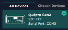
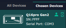
Click Connect > Search Device.
XPOSE searches for available devices through the selected communication interface.
After the search is complete:
- Select the target device from All Devices.
- Move it to Chosen Devices.
The device is now ready for configuration.
 | 👉 |  |
|---|
Input and Output Configuration
Input and Output Configuration
The rear panel of Q16pro Gen2 is displayed in the workspace. Each input and output port can be configured independently.
Interface colors indicate signal status:
| Interface Color | Description |
|---|---|
| Red animated border | Selected signal |
| Green | Normal signal |
| Yellow | Abnormal signal |
| White | No signal |
📢  Notes

Due to hardware limitations, the SDI output interface always appears white regardless of its signal status.
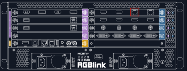
| Port Color | Icon | Description |
|---|---|---|
| Purple |  | Input port |
| Blue |  | Output port |
| Yellow |  | Communication port |
Input Configuration
Click an input port to select the board that contains the port. Configure the selected input port in the settings panel.
The selected port is highlighted with a red animated border.
Set EDID for the input port. The 4K settings appear when a 4K input module is installed.
EDID
Input Port: Displays the selected input port.
Basic Parameters
- Monitor Name: Enter the monitor name.
- Width / Height / Frequency: Enter custom parameters as required.

The following Q16pro Gen2 input modules support EDID:
- Quad HDMI 2.0 Input Module.
- Dual HDMI 2.0 & Dual DP 1.2 Input Module.
- Quad DVI Input Module.
- Dual HDMI 1.3 & Dual DVI Input Module.
For order codes, see Q16pro Gen2 Specification.
4K
Input Module: Displays the position of the selected port.
Basic Parameters > Input Source: Select an input port on the 4K input module.

Communication Board with PVW
When a Communication Board with PVW input module is installed on Q16pro Gen2, click an HDMI port to configure the following settings.
📢  Notes

4K signals are synchronized in PGM but may not be synchronized in PVW.
| Item | Illustration | Description |
|---|---|---|
| Frame | 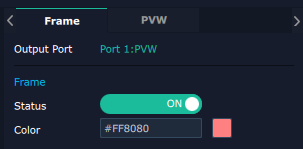 | Status: Turn on status to set the frame color. Color: Set the frame color. |
| PVW | 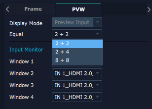 | Display Mode:Preview Input ONLY. Equal: Select 2+2 / 2+4 / 2+8 layout. Input Monitor: Select the input signal for each window. |
Output Configuration
Select the output port to configure, then click the properties icon.
Output Resolution
The Resolution page configures the output resolution, Genlock, brightness, and output protocol.
| Item | Illustration | Description |
|---|---|---|
| Resolution | 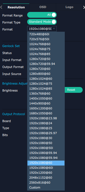 | SDI and HDMI output modules support output resolution settings. Format Range + ALL: Set the same output resolution for all output modules. + MODULE: Set the same output resolution for all output ports on the selected module. Other modules can use different resolutions. Format Type + Standard Mode + Customize. Enter Width, Height, and Refresh Rate, then click Set. |
| Genlock Set | 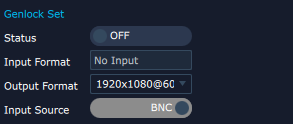 | Status: Turn the Genlock function on or off. Input Format: Displays the current input format. Output Format: Displays the current output format. Input Source: Switch to HDMI or BNC. |
| Brightness Adjustment | 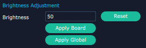 | Brightness: Set the brightness from 0-100. The default value is 50. Apply Board: Apply the brightness setting to all output ports on the selected module. Apply Global: Apply the brightness setting to all output modules. |
| Output Protocol | 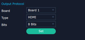 | Board: Select Current Board or All Board. Type: Select DVI or HDMI. Bits: The bit depth is fixed at 8 bits for DVI. Select 8 bits, 10 bits, or 12 bits for HDMI. |
OSD
The OSD function overlays text on the output video. Turn Status on before configuring OSD parameters.
The following Q16pro Gen2 output modules support OSD:
- Quad HDMI 1.3 Output Module.
- Quad 3G SDI Output Module.
- Quad DVI Output Module.
- Dual HDMI 2.0 Output Module.
- Dual HDMI 1.3 Output Module with Dante (preliminary).
For order codes, see Q16pro Gen2_Specification.
| Item | Illustration | Description |
|---|---|---|
| OSD | 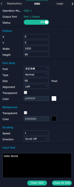 | Output Port: Displays the selected output port. Status: Turn OSD on or off. |
| Position | 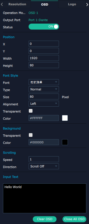 | X/Y: Set the horizontal and vertical starting position of the text. Width/Height: Set the horizontal and vertical size of the text. |
| Font Style | 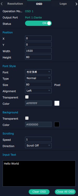 | Font: Select a font installed on the computer. Font Type: Select Normal, Italic, Bold, or Bold Italic. Font Size: Set the font size from 0-300 pixels. Alignment: Set the text alignment. |
| Background | 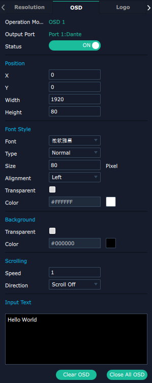 | Select a transparent background or set a background color. |
| Scrolling | 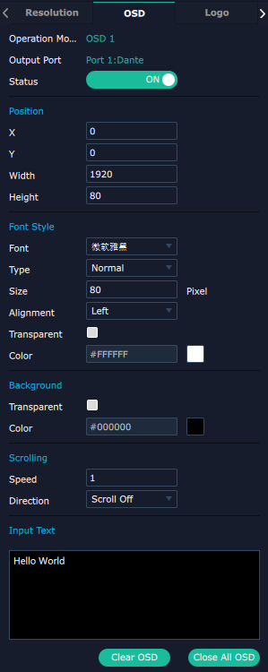 | Scroll Speed: Set the scroll speed from 0-16. Scroll Direction: Select Scroll Off or Scroll Left. |
| Input Text | 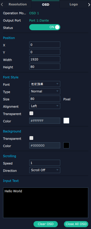 | Enter the text to display. |
| Clear OSD/Close All OSD | 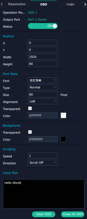 | Customize the OSD content, select Clear OSD to clear the current OSD, or select Close All OSD to disable all OSD. |
Logo
📢  Notes

Store the logo on an SD card before capturing it.
| Item | Illustration | Description |
|---|---|---|
| Output Port | 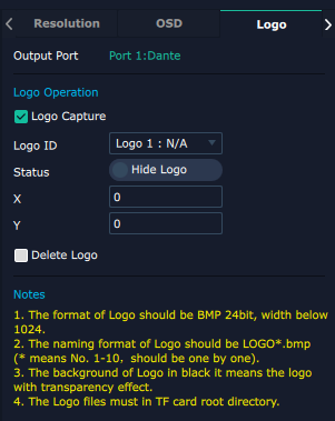 | Displays the selected output port. |
| Logo Operation | 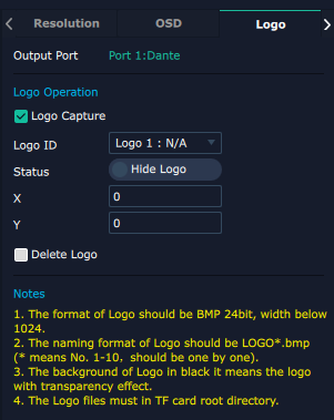 | Logo Capture: Select or cancel. Logo ID: Select a saved logo by its ID. Status: Show or hide. X/Y: Set the horizontal and vertical position Delete Logo: Delete the configured logo. |
Dante
Q16pro Gen2 supports the Quad Input & Quad Output Analog Audio Module. Install this module in a slot that supports both input and output modules.
Configure additional audio settings on the Layer Configuration > Dante page.
| Item | Illustration | Description |
|---|---|---|
| Output Port | 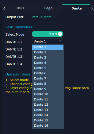 | Displays the selected output port. |
| Basic Parameters | 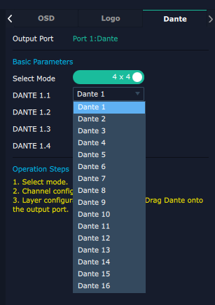 | Select Mode: Select 4×4 or 16×16. DANTE 1.1 - DANTE 1.4: Configure the audio channels. Click Set to apply the settings. |
Display Management
Display Management is used to create Containers and configure display layouts.
Click Display to open the Display Management page.
Q16pro Gen2 uses the Cross layout by default. To use a different layout, press and hold** × **in the upper-right corner of the current Container to delete it, then create a new Container.
Creating a Container
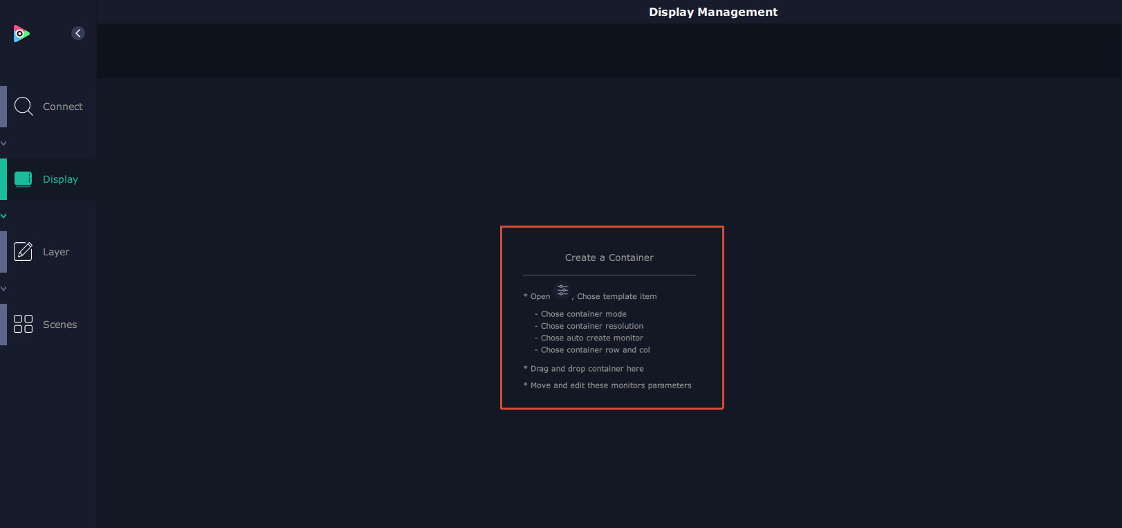
A Container defines the layout of the output displays. In XPOSE 2.0, a Container represents a complete display system, such as an LED display or an LCD video wall.
Click the properties icon, then configure the following:
- Chose container mode
- Chose container resolution
- Chose auto create monitor
- Chose container row and col
After the configuration is complete, drag the selected Container template into the workspace.
Configuring Displays
After creating a Container, you can adjust the display layout and position.
Click the properties icon to configure the Template, Output, and Display System.
Template
XPOSE 2.0 supports multiple display modes simultaneously. Each Container is identified by a different border color.
To create a Container, drag a template to the workspace.
| Item | Illustration | Description |
|---|---|---|
| Mode | 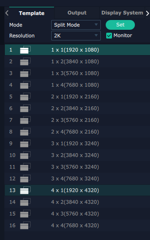 | Select a display mode. Each mode uses a different color. Matrix Mode (default): Retains the Container when you change the resolution. Split Mode: Deletes the Container when you change the resolution. Create a new Container after changing the resolution. |
| Resolution | | Select the output resolution. |
| Template | | The Template panel provides 16 basic display area layouts for creating Containers. |
Custom Template
Select Template > Customize to create a custom Container.
Set Monitor Layout to Auto or Manual.
Create a Container as follows:
- Enter H Total, V Total, Row, and Column. XPOSE 2.0 automatically calculates H Item and V Item.
- Click Create. The Container appears in the workspace and displays the width and height of each display.
- Click Save to save the Container.

Adjusting the Container Layout
The following operations are supported:
- Move: Drag the Container border to reposition it within the workspace.
- Zoom: Click - or +, or use the mouse wheel while the pointer is inside the Container.
- Delete: Press and hold × in the upper-right corner of the Container.
Output
The Output panel lists all output ports.
- Active ports are available.
- Gray ports are unavailable or already assigned.
To assign an output, drag the desired output port onto a display in the Container.
To replace an assigned output, drag another output port onto the target display. The original output becomes available again.

Display System
The Display System panel lists all created Containers.
Click the Edit icon (🖋) to rename a Container.

Layer Configuration
The Layer Configuration page manages layers assigned to each output.
Click Layer to open the Layer Configuration page.
The left panel displays the available Display Area, Dante, IPC, Layer, and Signal.
Display Area
The Display Area panel lists all Containers created in Display System.
Select a Container to display it in the workspace.

Dante
The number of Dante signals depends on the selected mode in Output Settings: four in 4 × 4 mode, and 16 in 16 × 16 mode.
- Select a bank.
- Drag an audio input from Signal List to the Container.
- Drag another audio input to replace the current input.

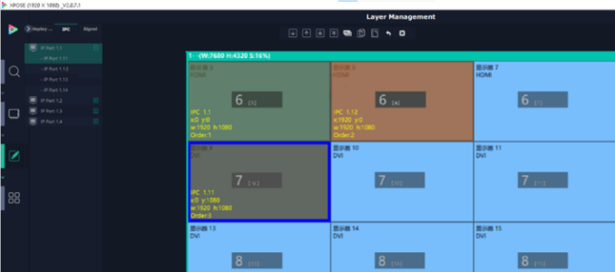
IPC
IPC stands for IP Camera.
This page displays IP camera signals received through the IP input module.
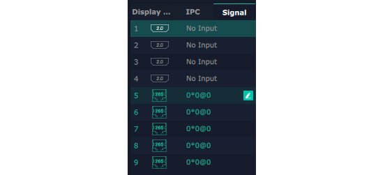
Signal
Displays all available input signals.
Drag a signal from the list onto the desired display within a Container.
By default, each signal is identified by its input resolution.
To rename a signal, click the Edit icon (🖋), enter a new name, then click √.
📢  Important

XPOSE uses an S-shaped connection order by default.

Connect the displays to the output ports in the same order to ensure correct image mapping. Each output port connects to one display.
| Status | Illustration |
|---|---|
| Correct | 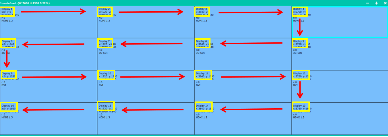 |
| Incorrect: Display 1, 2, 3 and Display 4 are separated | 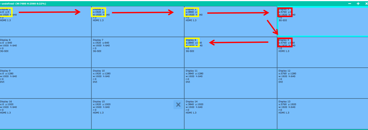 |
| Incorrect: Display 5, 6 and Display 7, 8 are separated | 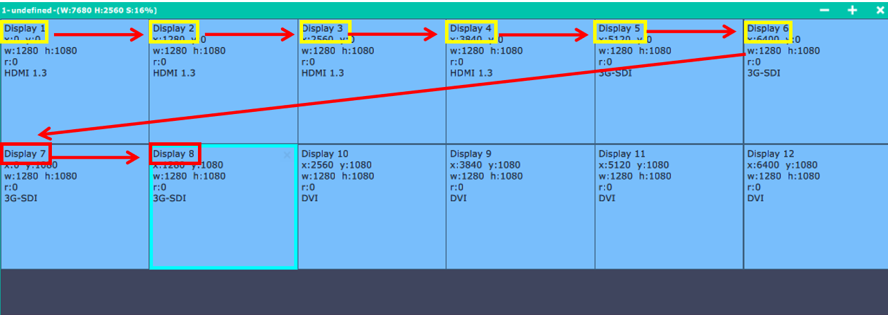 |
Layers
After a signal is assigned to a display, the Layers panel lists the corresponding layer number and signal.
The toolbar provides the following operations:
- Bring to Front
- Move Forward
- Move Backward
- Select All
- Copy
- Paste
- Delete
📢  Notes

One signal occupies one layer. A 4K signal occupies four layers.

Users can drag the same signal into a Container multiple times.

Available Layers
The number displayed on each output indicates the remaining available layers.
As signals are added, the available layer count decreases. When no layers remain, additional signals cannot be assigned.
**Layer number: **16 layers in total can be places on each output port. The number in the red rectangle on the right figure represents the number of layers that can be placed at the output.

Editing Layers
Select a layer, then click the properties icon.
Scaling and Cropping
Layers can be adjusted using either of the following methods.
Method 1
Select the layer and enter the X Position, Y Position, Width, and Height at the bottom of the workspace.
Click Save to apply the changes.

Method 2
Open the properties icon > Scale, then enter the X Position, Y Position, Width, and Height.
Click the Lock Aspect Ratio icon to maintain the aspect ratio when resizing.

Quick
Quick page provides a fast way to set the layer layout.
Drag and drop a source from Signal List onto the workspace. Click Set to apply the layout.
| Illustration | Description |
|---|---|
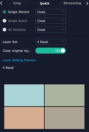 | Single Monitor: Select the Output Port to configure. Single Board: Select the Output Board to configure. All Monitors: Turn all monitors on or off. Layer Set: Set the layer layout. |
| Layer Setting Preview |
Streaming
The H.265 Module supports image preview.
Image Quality supports smooth (default), normal, or HI-Q.
Enable preview as follows:
| Illustration | Step |
|---|---|
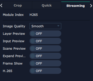 | 1. Turn on Layer Preview, Input Preview, Scene Preview, or Expand Preview as required. |
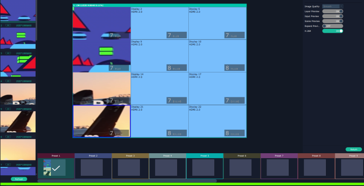 | 2. Turn on H.265 to preview the image. |
📢  Notes
H.265 is the master switch.

If H.264 is enabled first, H.265 can not be enabled successfully.
Scene Management
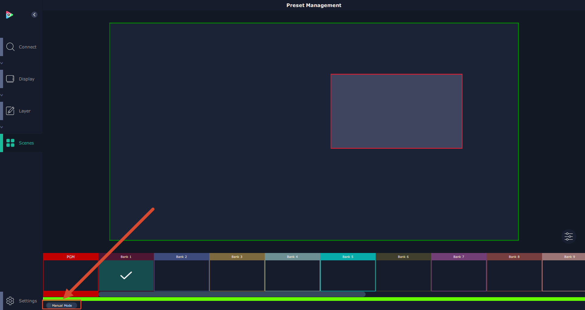
Click Scenes to open the Scene Management page.
Click the button in the lower-left corner to switch between Manual Mode and Schedule Mode.
Schedule Mode
Schedule Mode automatically recalls scenes according to a scheduled timetable.
To configure scheduled playback:
- Enable Schedule Mode.
- Select the Loop Mode.
- Select the desired scene Bank.
- Set the start and end times.
- Click OK.
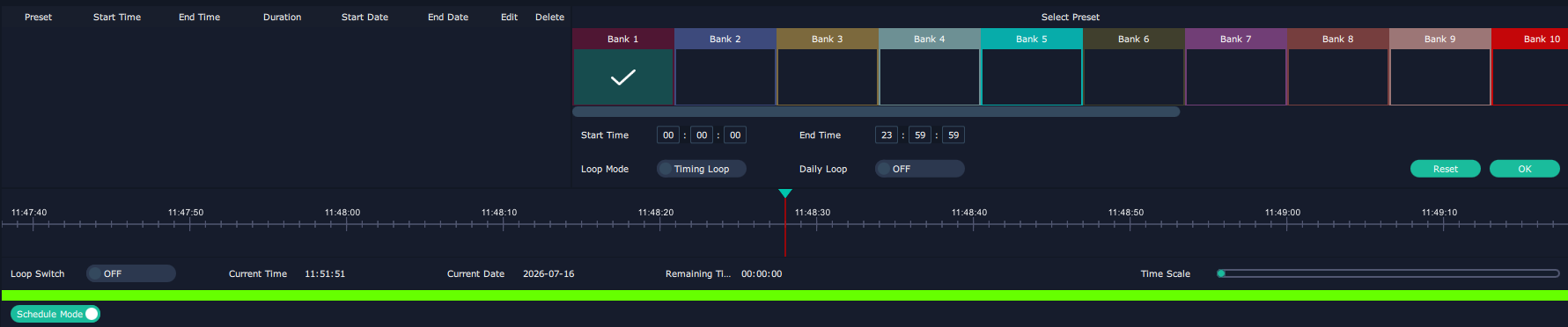
To edit or delete an existing schedule, click the corresponding Edit or Delete icon, then enable the schedule.

Manual Mode
Switch to Manual Mode, select a scene, then click the properties icon.
The following options are available:
- Take Setting
- Preset Name
- Script
- Hotkey
Take Setting
Click CUT to switch from PVW to PGM immediately.

Page
| Item | Illustration | Description |
|---|---|---|
| Save Page | 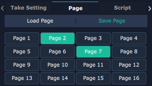 | Select a preset, click Save Page, then select Page X to save the preset to that page. A page with a saved preset is displayed in green. |
| Load Page | 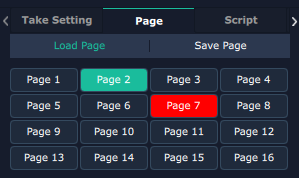 | Click Load Page, select a saved preset, and load it. The selected page turns red. |
Script
- In the script page, enter the File Path and File Name, and click Save. The file appears under Load Script.
- Click Load icon to load the file into XPOSE.
- Click Delete iconto delete the saved script.

Preset Name
Rename the current scene and assign a scene label color.

Hotkey
Displays the keyboard shortcuts available for scene switching.
