Online Manual
mini-edge SDI User Manual

2 Install Your Product
mini-edge SDI provides a wide range of interfaces to support various production workflows.
This section explains how to connect video inputs, monitoring devices, microphones, and other peripherals.
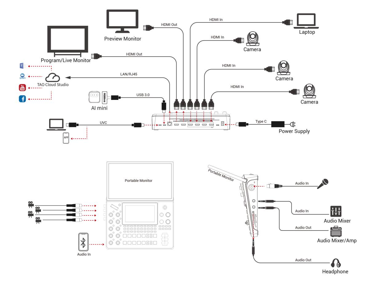
To Know RGBlink Portable MonitorA mounting slot for the RGBlink Portable Monitor is located on the top of the mini-edge SDI front panel. The expansion display provides additional monitoring space and improves operational efficiency.The RGBlink Portable Monitor features a full-function USB-C interface that supports both power delivery and audio/video transmission. It also includes a Mini HDMI port for connecting external displays, cameras, and other compatible devices.For information about purchasing the expansion display and related accessories, please contact your sales representative.
2.1 Connecting HDMI/SDI Input
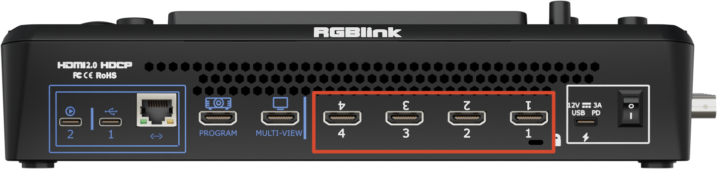
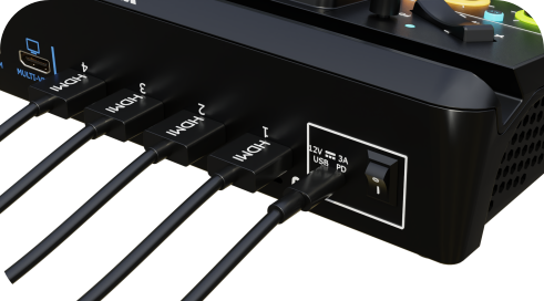
mini-edge SDI provides 4 HDMI input ports and 4 SDI input ports.
HDMI inputs support resolutions up to 4K@60Hz, while SDI inputs support automatic de-interlacing.
Any device equipped with HDMI or SDI output, such as a computer or camera, can be connected as a video source.
The built-in 5.5-inch display automatically detects and previews connected video sources after startup. An external monitor may also be connected via HDMI output for source monitoring or multiview operation.
 | 👉 |  |
|---|
📢  Notes

HDMI and SDI cables are not included and must be purchased separately.

Some cameras use Mini HDMI connectors. If required, purchase a Mini HDMI-to-HDMI cable separately.
2.2 Connecting HDMI Output
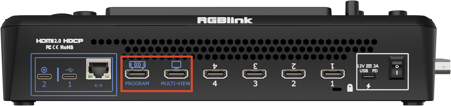
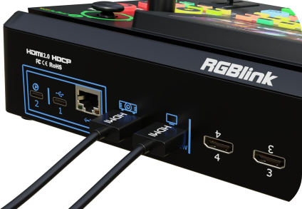
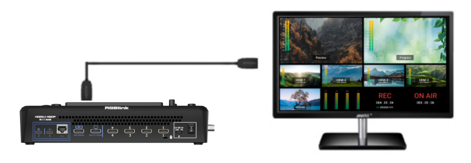
Use HDMI cables to connect the MULTI-VIEW and PROGRAM outputs of mini-edge SDI to HDMI-compatible monitors for simultaneous preview and program monitoring.
 | 👉 |  |
|---|
- MULTI-VIEW Output: Used for monitor connection and outputs the multiview display by default.
The multiview display provides real-time monitoring of HDMI 1–4 inputs, SDI 1–4 inputs, UVC input, Program output and Audio and system status.
- PROGRAM Output: Used for connection to projectors, LED displays, televisions, and other display devices. Program Output and Test Pattern modes are available.
Press ENTER and navigate to Output in the main menu to configure output content and output resolution for both MULTI-VIEW and PROGRAM outputs.
2.3 Connecting Microphone and External Monitoring Devices
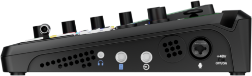
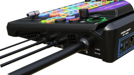
The right-side panel integrates audio input and output interfaces, supporting 2 external audio inputs and 2 audio outputs for live streaming, production, and audio mixing applications.
 | 👉 |  |
|---|
2.3.1 Audio Inputs
- Line In
The Line In connector uses a 6.35 mm TRS jack and supports connection to computers, smartphones,tablets, audio mixers and other audio devices.
- MIC Input
The MIC input uses a combo XLR/TRS connector and supports 48V phantom power.
It can be connected directly to powered or passive microphones.
- When connecting dynamic microphones, wireless microphone receivers, or other audio devices, phantom power must remain disabled.
- Enable phantom power only when using a condenser microphone that requires 48V power.
-
Connecting a Microphone
- Make sure 48V phantom power is turned off.
- Turn the MIC level down to minimum.
- Connect the XLR cable securely to the microphone and the device.
- Enable 48V phantom power.
- Gradually raise the MIC level to the desired volume.
-
Disconnecting a Microphone
- Turn the MIC level down to minimum.
- Disable 48V phantom power.
- Wait approximately 5–10 seconds for any residual voltage to dissipate.
- Disconnect the XLR cable and remove the microphone.
-
📢  Important
Do not connect or disconnect microphones or XLR cables while 48V phantom power is enabled, as this may damage the device or the connected microphone.
2.3.2 Audio Outputs
- Line Out: 6.35 mm main audio output.
- Headphone Output: 3.5 mm headphone monitoring output for real-time audio monitoring.
- Bluetooth Audio: To accommodate laptops and mobile devices without dedicated audio output ports, mini-edge SDI includes a high-fidelity Bluetooth audio module. Users can connect compatible devices wirelessly for stable audio input. For details, refer to Bluetooth.
- Embedded Audio: In addition to external audio inputs, mini-edge SDI supports embedded audio from HDMI/SDI sources. Combined with external inputs, the system supports processing up to 8 audio input channels simultaneously.
- Audio Control: The front panel provides:
- AFV (Audio Follow Video) switching for HDMI/SDI embedded audio
- Audio control knob for volume adjustment, monitoring, and mixing
HDMI and microphone audio delay adjustments are also available to improve audio/video synchronization. For details, refer to Audio Management.
📢  Notes

1. To prevent speaker damage or loud pops
- Connect audio cables before powering on speakers.
- Power off speakers before disconnecting audio cables.
2. Wireless microphone connection
- The MIC input supports wireless microphones via a 3.5 mm female-to-6.35 mm mono adapter.
- The Line In input supports wireless microphones via a 3.5 mm female-to-6.35 mm stereo adapter.
3. Audio signal limitations
- Balanced signals are supported only on MIC inputs.
- Stereo input signals are supported only through the Line In interface.
2.4 Connecting USB for Streaming and Recording
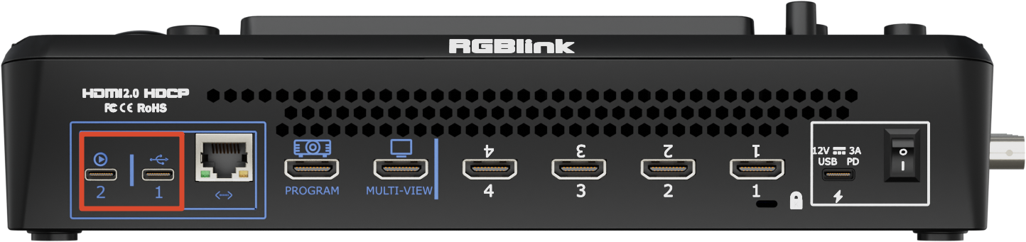
mini-edge SDI provides two USB 3.0 ports for streaming and local recording.
2.4.1 USB 3.0 Port 2
Supports UVC output.
When connected to a computer via USB, mini-edge SDI is recognized as a standard USB webcam.
The device can then be selected as a video source in applications such as OBS Studio, Bilibili and other compatible streaming platforms.
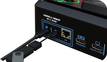
2.4.2 USB 3.0 Port 1
Supports local recording and media import.
Users can connect USB flash drives or SSDs for recording.
Supported storage media:
- USB flash drives up to 64 GB
- SSDs up to 2 TB
- exFAT file system
 | 👉 |  |
|---|
📢  Notes

- USB 3.0 flash drives are recommended for optimal recording performance.
- SSDs are recommended for external storage. Verify whether additional power is required before use.
- The OTG cable used for recording supports file transfer only and cannot be used for live streaming.
- Simultaneous multi-platform streaming, or using UVC output while recording, may increase CPU utilization and result in dropped frames or video stuttering.
- Internal USB-C data transmission operates over USB 3.1.
2.5 Connecting Router
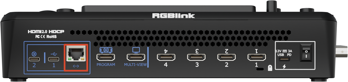
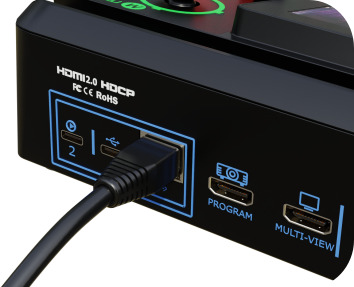
- Connect the Ethernet port of mini-edge SDI to a router using a CAT6 Ethernet cable.
 | 👉 |  |
|---|
- After pressing MENU, navigate to SETTING > NETWORK > Turn OFF DHCP
- Enter the desired IP address using the numeric keypad.
- After entering the address, rotate the ENTER knob to highlight Confirm, then press ENTER to save.
- Ensure that the router IP address and the mini-edge SDI IP address are within the same subnet.
- If DHCP is enabled on both the router and mini-edge SDI, manual IP configuration is not required. The device will automatically obtain an IP address from the router and communicate with other devices on the network.
- Enter the device IP on your browser, then the web will display the Web APP control panel.
2.6 Connecting Power
RGBlink mini-edge SDI package includes a PD 12V/3.3A power adapter and power cable.
Before connecting the power supply, make sure the power standard in your country or region is supported.
Firmly connect the power cable to ensure stable power delivery to the device.
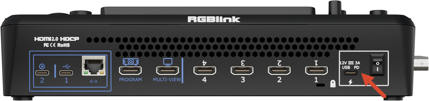
📢  Important

It is recommended to use the power adapter included with the package.

If another adapter must be used, make sure it meets the following requirements:

- Supports the PD fast charging protocol
- Uses a USB-C power port with reversible plug orientation
- Provides up to 40W of PD output power
- If the power adapter has two ports, use only the USB-C port for powering mini
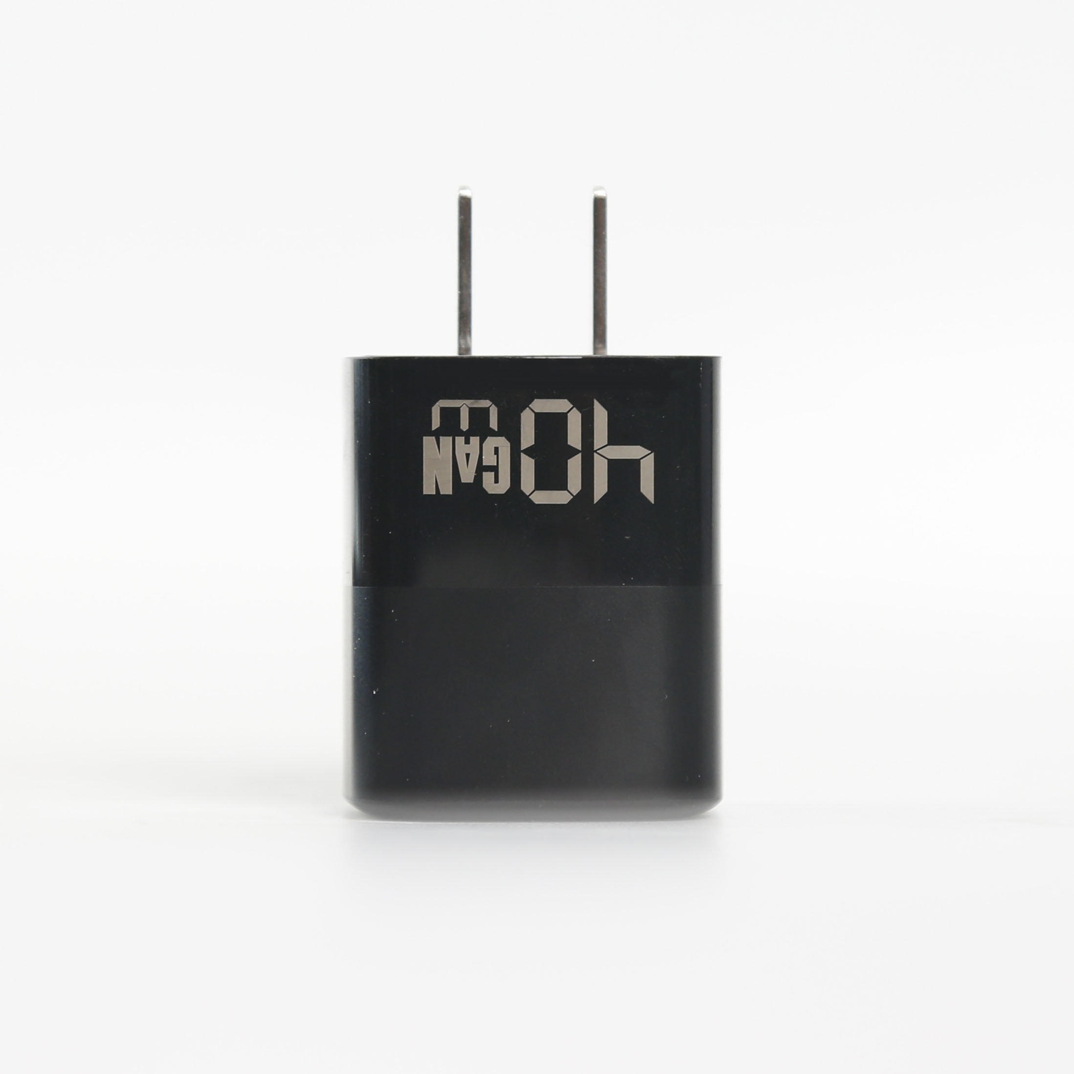
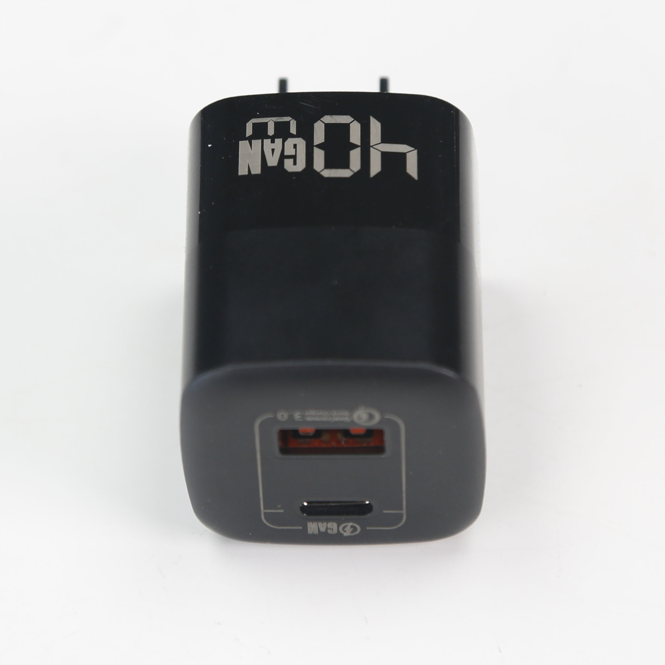
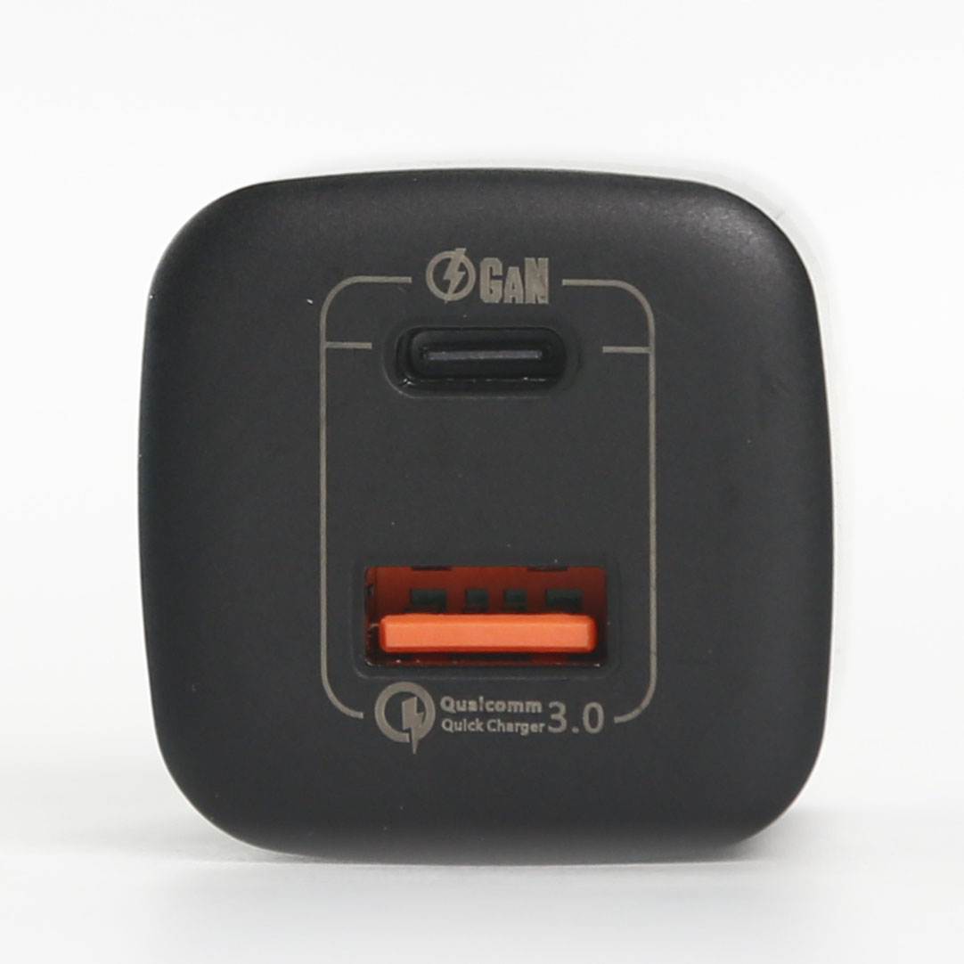
The following image shows the standard power adapter included with mini series for reference:
 |  |  |
|---|
2.7 Powering On mini-edge SDI
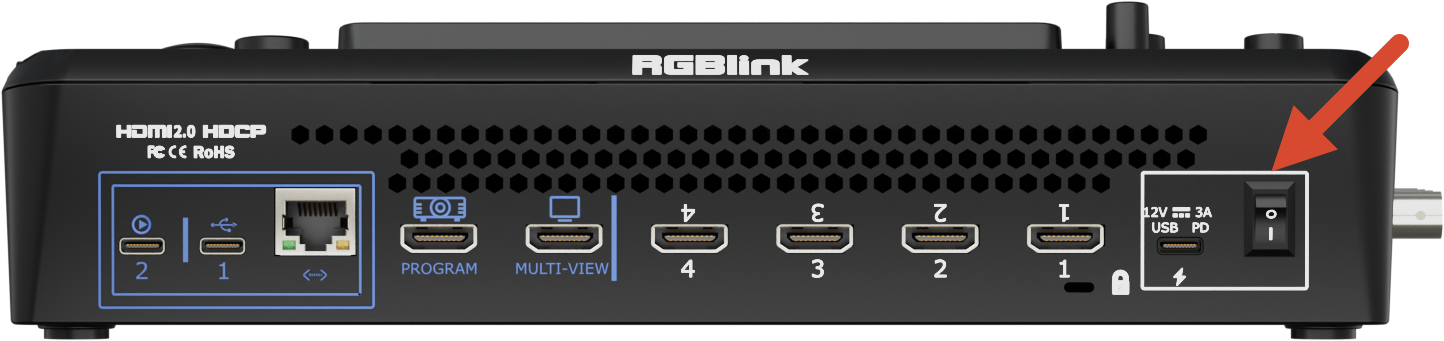
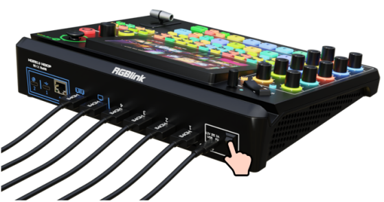
After all power, input, and output connections have been completed, press the rocker power switch downward to power on the rear panel.
 | 👉 |  |
|---|
After startup, the full-color display will show the mini-edge SDI logo before entering the main operating interface.