Online Manual
mini-extreme ISO User Manual

3.3 Input
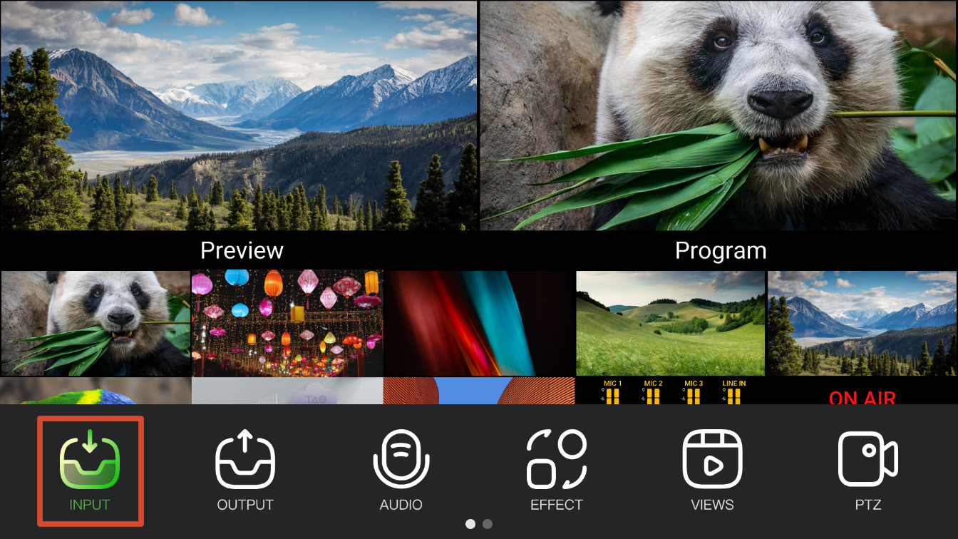
INPUT settings are used to assign signal sources to IN 1-8, including HDMI 1-4, SDI 1-4, NDI and UVC sources.
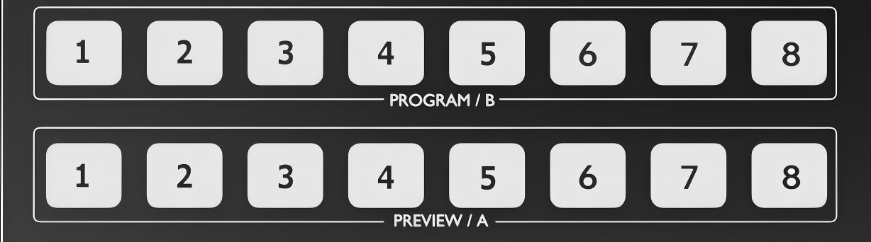
IN 1-8 correspond to the buttons on the PROGRAM/B and PREVIEW/A rows from the front panel (as highlighted in the box) .
After a souce is connected, the button indicator displays the corresponding status.
| Indicator Status | Description |
|---|---|
| Solid Green | The signal is currently displayed in PREVIEW. |
| Solid Blue | The signal is being editing. |
| Solid Red | The signal is currently displayed in PROGRAM. |
| Off | No signal is detected. Or the signal format is not supported. |
3.3.1 IN1-6
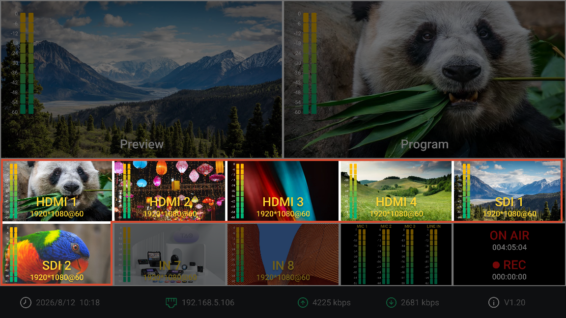
IN1-6 are assigned to HDMI and SDI input sources.
After connecting a source as described in chapter 2. Install Your Product, the corresponding input is displayed in the HDMI/SDI monitoring area on the main interface.
| Input | Source |
|---|---|
| IN 1-4 | HDMI 1-4 |
| IN 5 | SDI 1 or SDI 2 |
| IN 6 | SDI 3 or SDI 4 |
Configuration
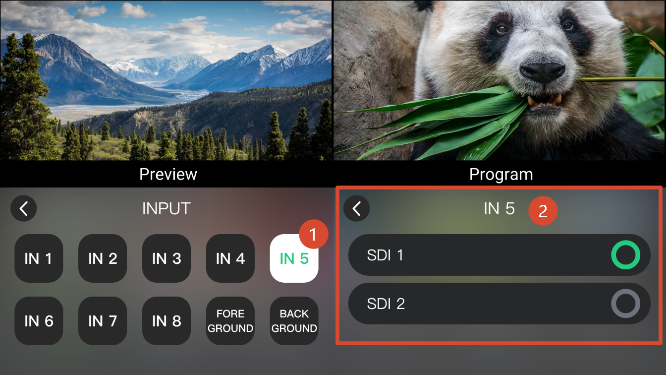
The following example shows how to configure IN 5:
- Press MENU to open the menu.
- Select INPUT.
- Select IN 5.
- Select the signal source.
EDID Management
IN 1-4 support EDID management.
Click the ⚙icon in the upper-right of the INPUT page to open EDID management page.
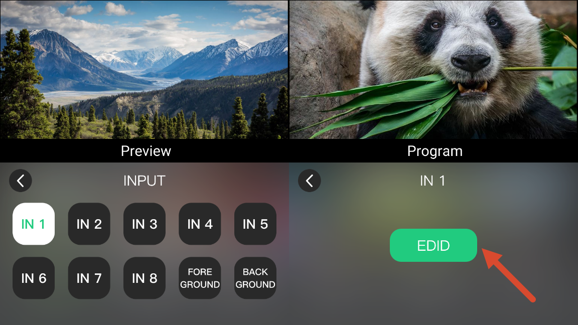 | 👉 | 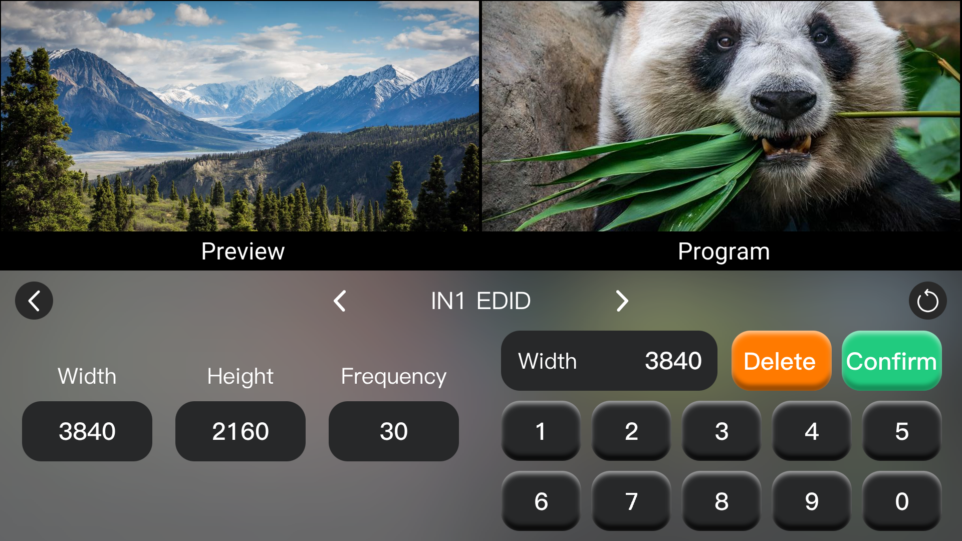 |
|---|
The following parameters can be configured using the on-screen numeric keypad.
| Parameter | Range |
|---|---|
| Width | 800-3840 |
| Height | 600-2160 |
| Frequency | 25-120 fps |
3.3.2 IN7-8
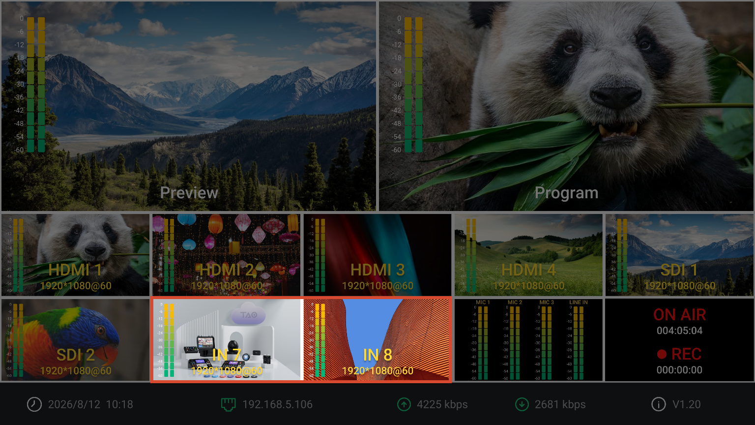
IN 7 and IN 8 support UVC camera sources and NDI video streams.
Select either a local UVC source or an NDI source on the local network as required. The assigned sources are displayed in the IN 7 and IN 8 monitoring area on the main interface.
📢  Important

IN7 and IN8 are mutually exclusive. If one is set to UVC, the other only supports NDI.
Configuring a UVC Source
- Connect a UVC cameras using the H.264/H.265 video encoding format to the UVC port.
- Select IN 7 or IN 8.
- Set the input type to UVC.
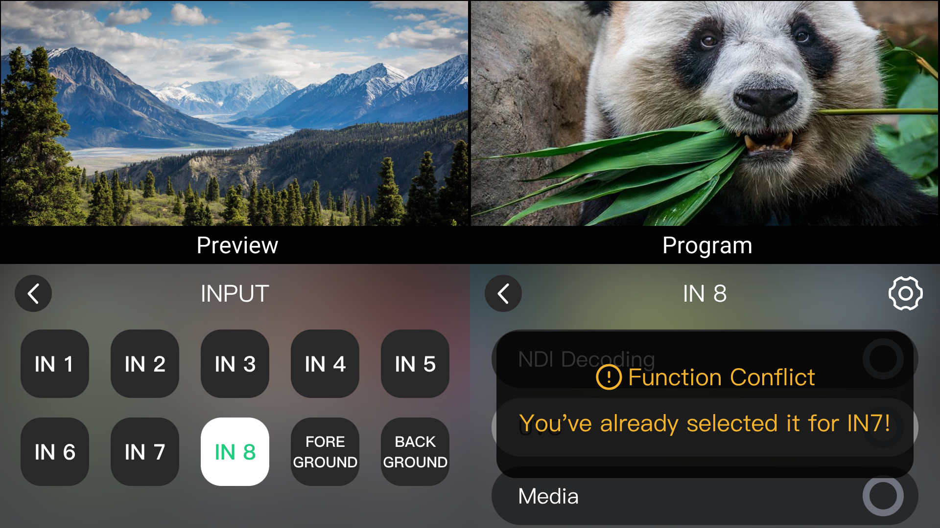
If UVC has already been assigned to either IN 7 or IN 8, the other input cannot be configured as UVC. A "Function Conflict" message will be displayed.
📢  Notes

UVC input supports only UVC cameras using the H.264/H.265  video encoding format.

MJPEG encoded video streams are not supported.
Configuring a NDI Source
NDI decoding requires TAO Cloud binding and authorization.
- Bind the device according to chapter 3.15 TAO Cloud.
- Go to My Collection > Device and select the device.
- In Setting > NDI Authorization, enter an email address to receive the authorization code, then click Authorization.
- Enter a valid NDI authorization code in the pop-up window and click NDI Enable to activate NDI decoding.
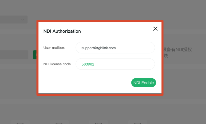
On the INPUT page:
- Ensure mini-extreme ISO and the NDI source are connected to the same LAN.
- Select IN 7 or IN 8 and set the input type to NDI Decoding.
- Click the arrow on the right, then tap Enable.
- Click Refresh.
- Select the target NDI source from the device list.
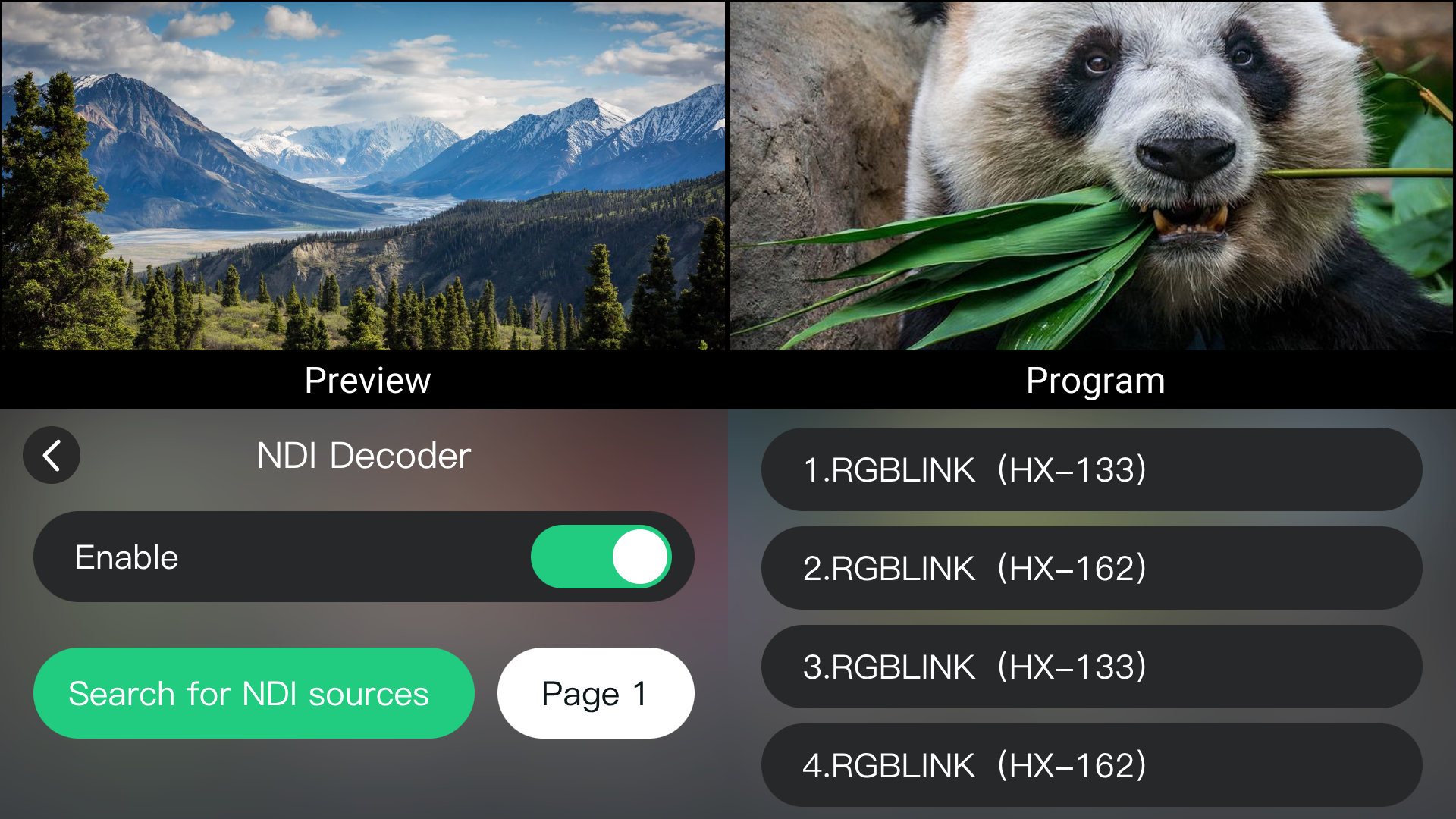
- Ensure mini-extreme ISO and the NDI source device are connected to the same local network.
- Select IN 7 or IN 8, then set the input type to NDI Decoding.
- Click ⚙ then Enable.
- Click Search for NDI Sources.
- Select the target NDI source from the device list. Use the page controls to switch between pages.
3.3.3 Background and Foreground
Background and Foreground are used to display media assets when no input signal is available or when overlay content is required.
- Background displays a fixed background image or replaces a black screen.
- Foreground displays overlay elements such as logos, corner graphics, and masks.
📢  Notes

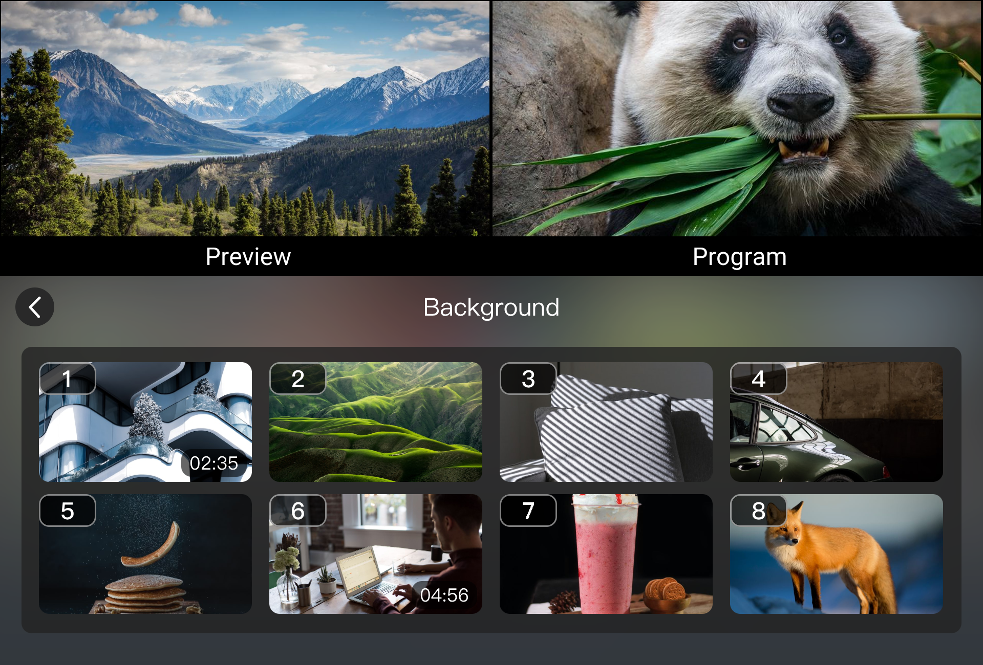
Media assets must be imported into the media library before use. See 3.5 About Layers, Importing Materials for more details.
Configuration
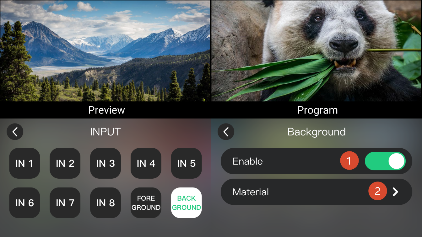
- Select INPUT menu
- Enable BACKGROUND or FOREGROUND.
- Click Material to open the media library and select an asset.
 | 👉 |  |
|---|